| Author |
 Topic Search Topic Search  Topic Options Topic Options
|
dfwallis 
Orange Level

Joined: 09 Mar 2023
Location: DFW
Points: 949
|
 Post Options Post Options
") Thanks(0) Thanks(0)
 Quote Quote  Reply Reply
 Posted: 16 Oct 2023 at 6:45pm Posted: 16 Oct 2023 at 6:45pm |
 JK in Pa wrote: JK in Pa wrote:
I believe I see valve rotators on the exhaust valves. I always thought valve rotators required offset rockers. |
Offsetting was sometimes used in small engines when no valve rotation device was present to achieve rotation. Offsetting is not supposed to be needed with a valve rotation device. It certainly should not be so far off that it's barely contacting the valve stem and leaving giant divots because of force being limited to a tiny contact area.
|
 |
|
Sponsored Links
|
|
|
1955CA
Orange Level
Joined: 10 Sep 2018
Location: Ontario, Canada
Points: 602
|
Post Options
Thanks(0)
Quote Reply
Posted: 18 Oct 2023 at 10:45am |
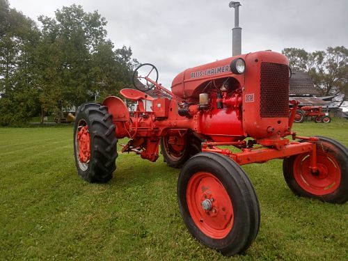
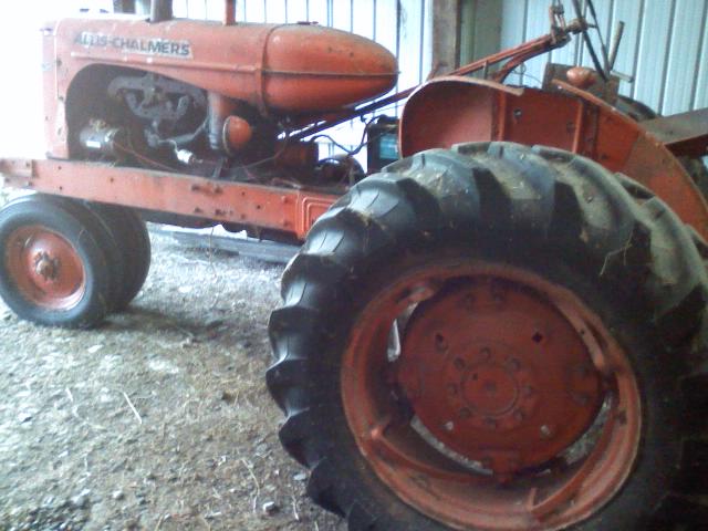
Any update pics DFWallis? That looks wicked with the big tires. I just went stock size on my rear replacements. Can't wait to see it all put back together after you had the body parts painted.
I just came in from my morning fall ride on mine. Took the dog for a walk, so figured I'd give Allis a run too. 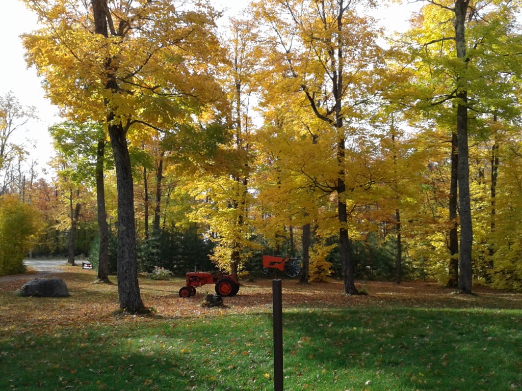 |
|
dfwallis
Orange Level
Joined: 09 Mar 2023
Location: DFW
Points: 949
|
Post Options
Thanks(0)
Quote Reply
Posted: 18 Oct 2023 at 5:56pm |
1955CA wrote:
Any update pics DFWallis? That looks wicked with the big tires. I just went stock size on my rear replacements. Can't wait to see it all put back together after you had the body parts painted.
I just came in from my morning fall ride on mine. Took the dog for a walk, so figured I'd give Allis a run too. |
I just posted updates a few days ago. It's not back together yet but mostly finished the engine rebuild internals. I'm working on some hydraulic system mods at the moment. I'm creating a pedestal out of a trailer pintle hitch and a hitch extension to get me the required height above the tires. I've got the base complete except for painting. I'll start on the platform for mounting the spools tomorrow when a connector arrives and i can determine the width of the side by side spool sets/valves. I don't expect any significant progress before the spring. I hate working in the cold :(
|
|
1955CA
Orange Level
Joined: 10 Sep 2018
Location: Ontario, Canada
Points: 602
|
Post Options
Thanks(0)
Quote Reply
Posted: 18 Oct 2023 at 7:48pm |
dfwallis wrote:
1955CA wrote:
Any update pics DFWallis? That looks wicked with the big tires. I just went stock size on my rear replacements. Can't wait to see it all put back together after you had the body parts painted.
I just came in from my morning fall ride on mine. Took the dog for a walk, so figured I'd give Allis a run too. |
I just posted updates a few days ago. It's not back together yet but mostly finished the engine rebuild internals. I'm working on some hydraulic system mods at the moment. I'm creating a pedestal out of a trailer pintle hitch and a hitch extension to get me the required height above the tires. I've got the base complete except for painting. I'll start on the platform for mounting the spools tomorrow when a connector arrives and i can determine the width of the side by side spool sets/valves. I don't expect any significant progress before the spring. I hate working in the cold :( |
Awesome! I'll be watching for your future updates. You might teach me a few tricks to do to my CA.
|
|
dfwallis
Orange Level
Joined: 09 Mar 2023
Location: DFW
Points: 949
|
Post Options
Thanks(0)
Quote Reply
Posted: 30 Oct 2023 at 9:25pm |
Progress 10/30/2023: Designing a removable hydraulic console intended to bolt to the left side fender. The console consists of a pintle hitch, and a hitch extender mounted vertically with a custom tray resting on top of the extension which is removable. Two single acting valves mount to the side, a 4 spool valve set on the top. It sticks out over the tractor tire for space reasons. It may or may not fit exactly where I designed it to sit (may be too close to the seat), but I can move it forward or backward if needed. The tray itself is designed to slide left or right. I still have some plumbing work to go for the return. Perhaps a little goofy, but fun anyway (I'm retired, I got time) :) It weighs a ton...

The back view showing the mechanism for sliding the tray left or right.
It includes optional hose supports that can be added or removed when the dual acting spool valves on top are used.
Closeup of a hose support. Since the dual acting valve hoses will come off straight up, this supports them at about 16 inches (can be lowered) to prevent sharp bends.
|
|
steve(ill)
Orange Level Access
Joined: 11 Sep 2009
Location: illinois
Points: 90921
|
Post Options
Thanks(0)
Quote Reply
Posted: 31 Oct 2023 at 8:15am |
|
so the vertical hitch is just a way to mount it to the tractor , so you can easily remove it when not needed ? .... Instead of bolts ? .... I see the threaded rod which allows you to adjust it in that direction.
|
|
Like them all, but love the "B"s.
|
|
dfwallis
Orange Level
Joined: 09 Mar 2023
Location: DFW
Points: 949
|
Post Options
Thanks(0)
Quote Reply
Posted: 31 Oct 2023 at 11:31am |
steve(ill) wrote:
so the vertical hitch is just a way to mount it to the tractor , so you can easily remove it when not needed ? .... Instead of bolts ? .... I see the threaded rod which allows you to adjust it in that direction. |
The bottom (pintle mount) section will be bolted to the fender wall. I haven't drilled those holes (in the pintle bracket) yet so I can determine the best position. I measured it and know very close where the holes will go but I made the bracket a little longer in case I need to adjust it right or left. The top section is the removable part via the hitch pin. I'm trying not to physically modify the tractor, just using existing bolt patterns as much as possible. The threaded rod is designed to allow the tray to slide left or right (it is then tightened in that left or right position). I was thinking ahead to deconflict it with my idea for a roll bar/canopy mount that mounts to the axle but will rise just outside the fender wall (so the wheels will have to be slightly spun out). When that roll bar/canopy is installed, the tray will have to be slid right/forward to deconflict (since it sticks out over the tire). The pintle hitch is mounted to a piece of 4 inch x 4 inch angle iron that I cut out the left and right floor sections. The right section had to be cut to deconflict with the brake lever. The left side was only cut for symmetry. The forward fender bolt is around 4 inches from hole to back of brake lever. The other fender bolt is 11 inches behind the forward fender bolt. I have about an inch of play to adjust the position to deconflict with the brake lever and the seat.
The console is fairly well balanced. There is little stress on the mount when you operate the spool levers which have quite strong springs. That was one worry with only having two mounting bolts. I can add a horizontal support later if needed.
|
|
1955CA
Orange Level
Joined: 10 Sep 2018
Location: Ontario, Canada
Points: 602
|
Post Options
Thanks(1)
Quote Reply
Posted: 01 Nov 2023 at 5:35am |
|
Wow! Nice!
|
|
dfwallis
Orange Level
Joined: 09 Mar 2023
Location: DFW
Points: 949
|
Post Options
Thanks(0)
Quote Reply
Posted: 25 Jan 2024 at 3:14pm |
My first draft of the hydraulic return for a CA. I will first attempt return via filler cap as in below. If that doesn't work well, I have a better idea, but I think this will be ok if the flow is sufficient. Since the pump will be pulling out as fast as it's going back in, I don't anticipate problems, but I'll find out I guess. It's likely I'll have to reduce the size of the brass nut a little, but that's pretty easy. I may also need an o-ring. I had to bore the hole in the stainless fitting out to 3/8 inch (my poor drill bits). It was a 3/8 inch fitting with a 1/4" hole :( Was designed for super high pressure but not needed on the return line.
Edited by dfwallis - 25 Jan 2024 at 3:15pm
|
|
1952 CA13092, CA Pickup Plow, CA Cultivator, CA Two Row Planter, Dunham-Lehr GC78 Disc, Grader Blade, 3pt Fm180 Finish Mower
|
|
dfwallis
Orange Level
Joined: 09 Mar 2023
Location: DFW
Points: 949
|
Post Options
Thanks(0)
Quote Reply
Posted: 03 May 2024 at 12:12pm |
|
Traveling this weekend to resume work. I probably won't post real time due to lack of cell service, but expect a few progress pics late May or early June :) In order, finish engine work (rebuilt last fall), front tin work (partly complete, blast and paint, hopefully the de-dented gas tank is ready from the body work guy, you'd think 8 months would be enough time), rewire (partly complete), first start, then move on to the rear half (shifter back), finish steering wheel resurface (mostly complete), hand clutch rebuild, weld up and seal final drive oil pans, sand blast and paint rear half, complete custom 3pt mods and custom hydraulic mods last (well some will have to be done before I reinstall the platform). At some point I need to rework the front wheel bearings, but that can wait.
|
|
1952 CA13092, CA Pickup Plow, CA Cultivator, CA Two Row Planter, Dunham-Lehr GC78 Disc, Grader Blade, 3pt Fm180 Finish Mower
|
|
dfwallis
Orange Level
Joined: 09 Mar 2023
Location: DFW
Points: 949
|
Post Options
Thanks(0)
Quote Reply
Posted: 26 May 2024 at 11:05am |
Update 05/26/2024:
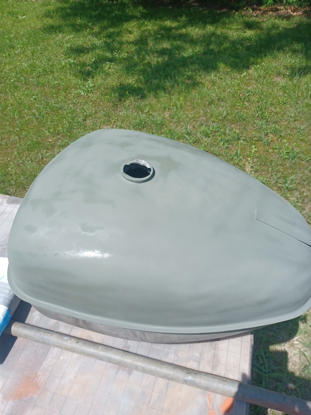
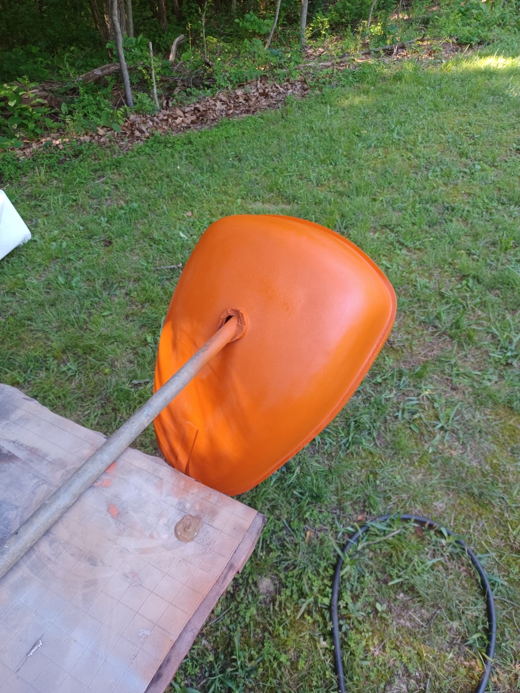
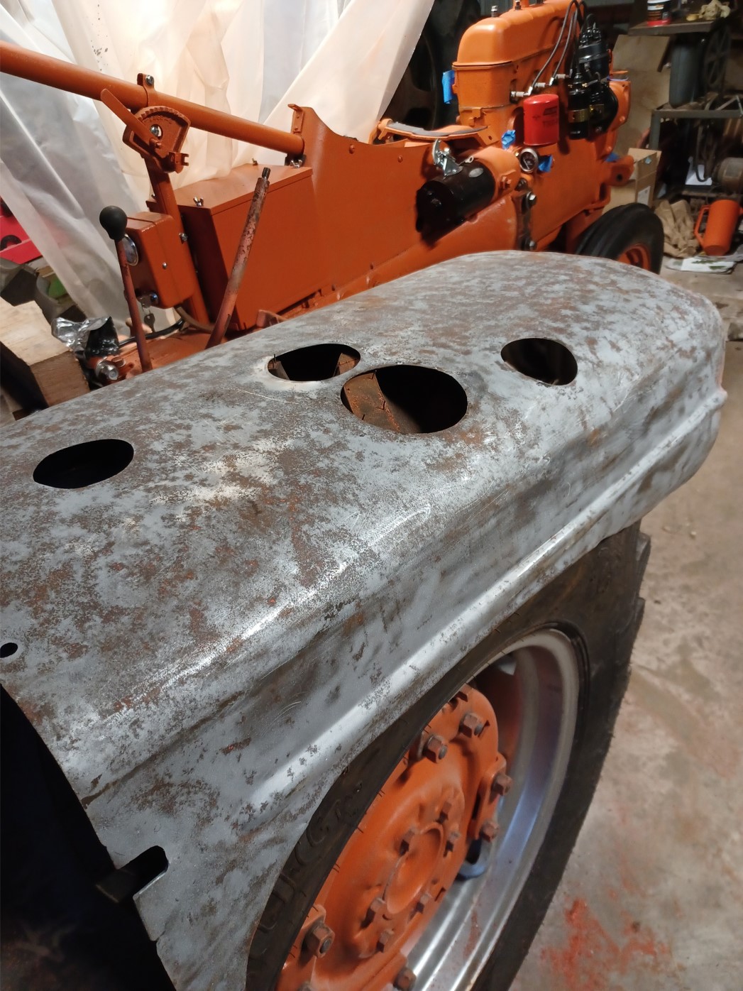
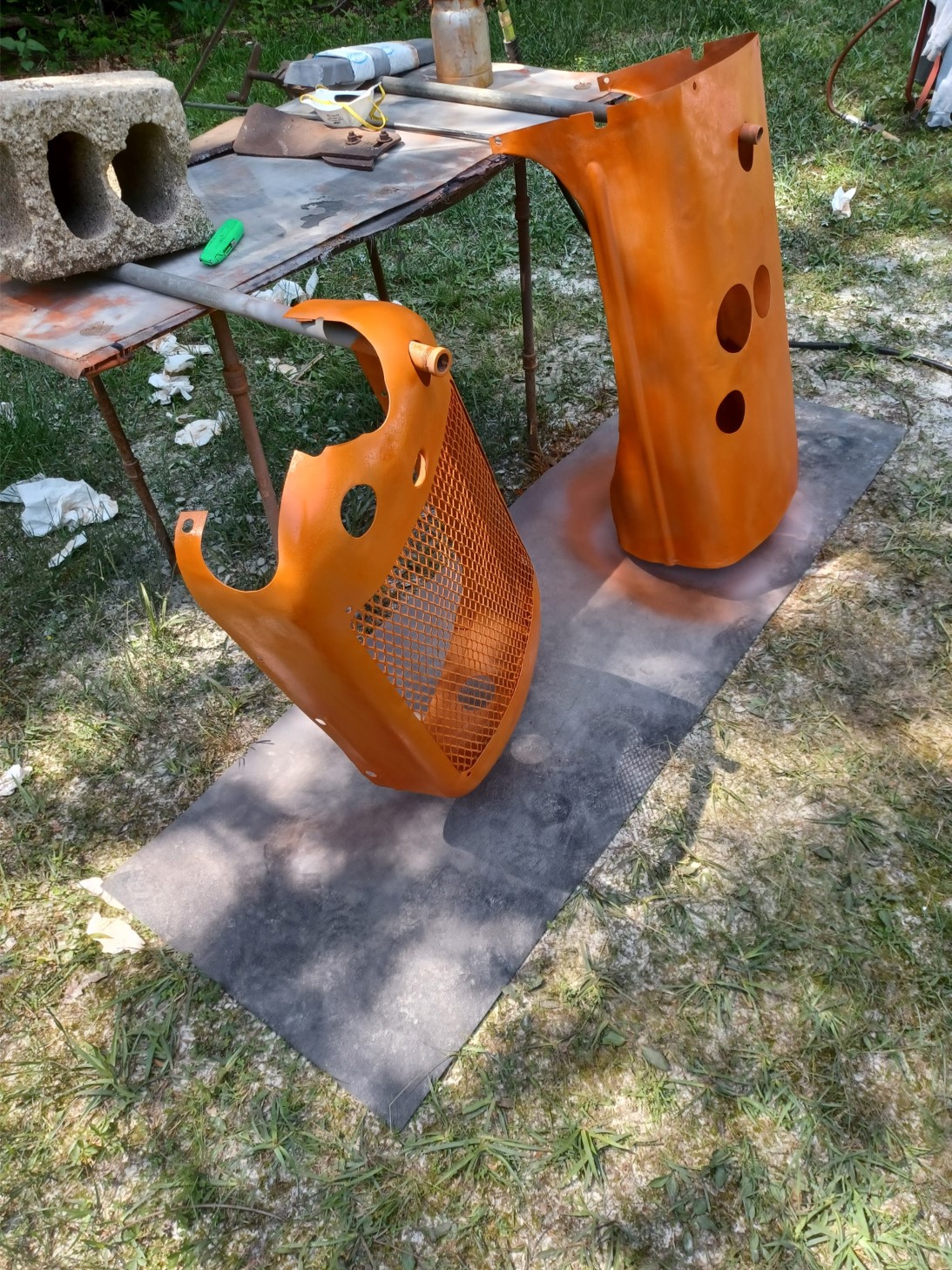
Quite a bit of trouble getting the severely dented gas tank fixed (someone felled a tree on it). First took it to a large body shop. They had it for a few weeks and decided they couldn't fix it (welded pins method). The metal was too thick and the pins detached. Then took it to a tractor renovation place and left it for 8 months (apparently out in the weather, I had to repeat the derust process). They assured me repeatedly they'd have it ready but when I finally arrived they had not been able to find anyone to work it. So I started driving from shop to shop and finally found a semi-retired guy to fix it (for a very reasonable price). He did a pretty good job given the condition (yes I could have replaced it). Needless to say, this caused quite a bit of delay/progress hindrance. It came out looking pretty good. The paint doesn't look quite as good as I'd like. Really bad conditions: 1) Indiana is pretty darn wet and humid in May and I just could not get the water down in the line. 2) Bugs galore. Wet paint seems like a bug magnet. 3) Sandable primer (600 grit) just never got smooth enough. 4) Oil based enamel paint takes weeks to dry and gets lots of dings if you're in a hurry. Doing it over I'd use a faster drying paint. The primer I used dries in minutes and is hard as a rock.
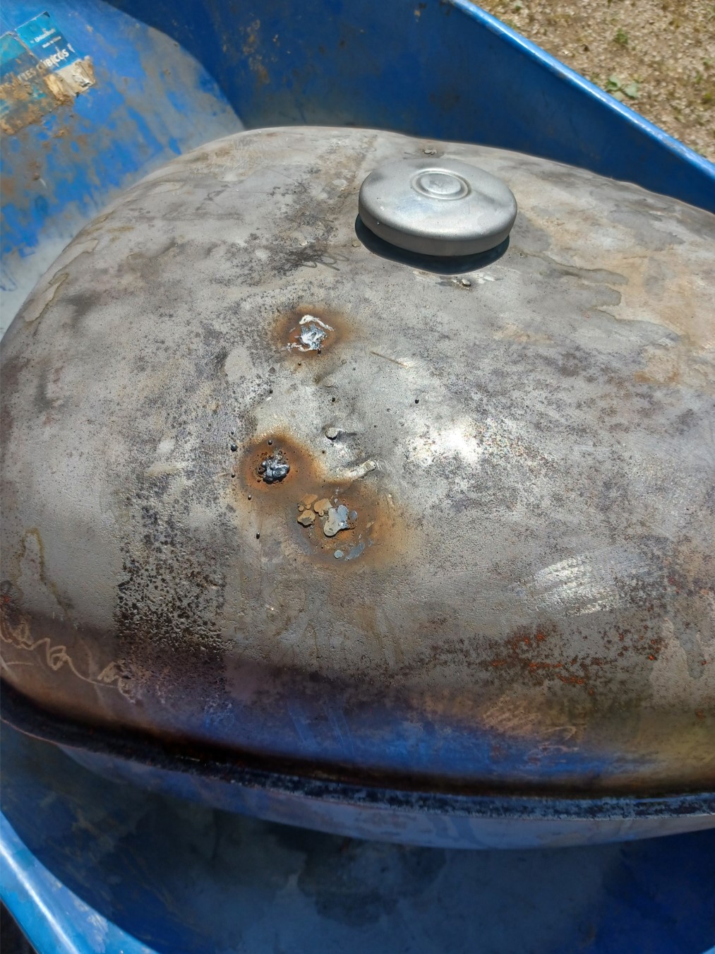
There were a few leaks in the top left over from the welded pins which I had to weld up. Then I used epoxy as the major filler and finished with a skim coat of bondo (no picture, I kept forgetting to take pictures).
Fit check. I should not have put the strap on yet. The paint was still too wet although dry to the touch. The strap goes on over the tin not the tank. Had to make a small paint repair to the tank but it will be hidden under the tin. I had used a rubber strip on the strap rather than a nylon strap material (fixed later). The rubber was really sticky and welded itself to the paint :( The tank was also internally derusted (6 or 7 times) and POR 15 gas tank sealer applied. That stuff seems pretty good. Hard as a rock, coated very well.
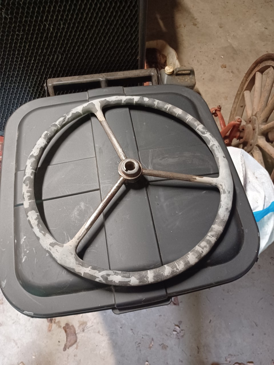
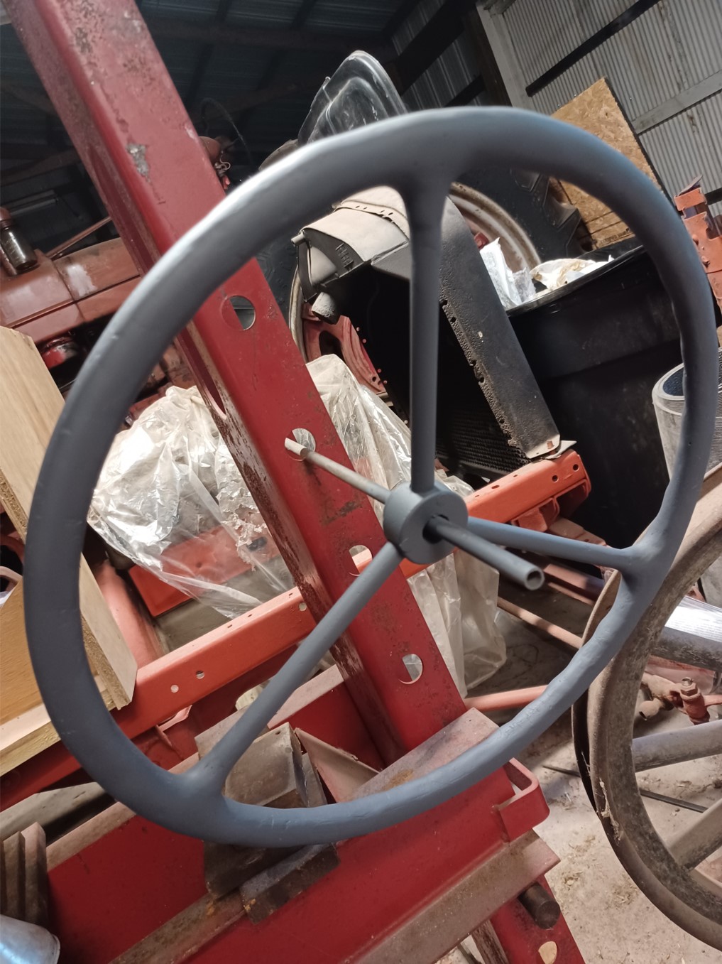
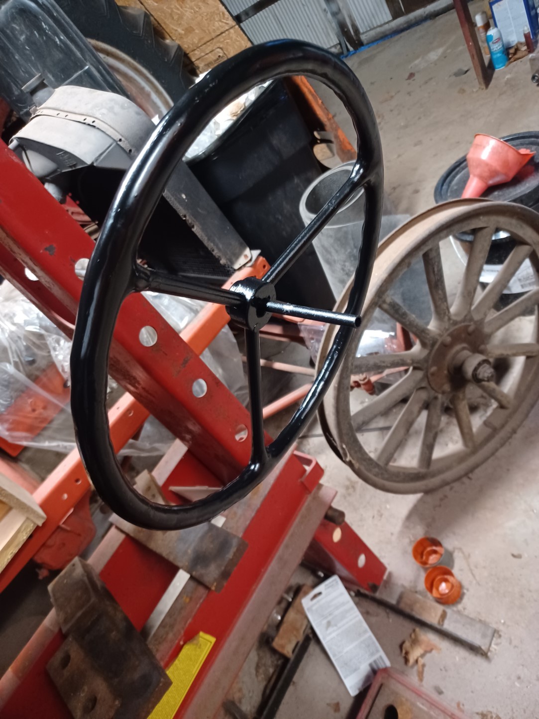
I worked on the steering wheel off and on between paint coats and maximized multitasking as much as possible. The original was in really bad shape with most of the bakelight near each spoke all or nearly all missing. That was a lot of small batch mixing. Yes I could have bought 2 of them for the price of the epoxy (not to mention my time). I could have spent a bit more time glazing. Epoxy isn't very well suited to that.
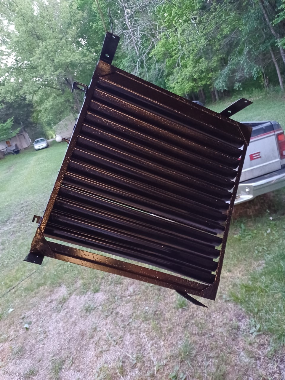
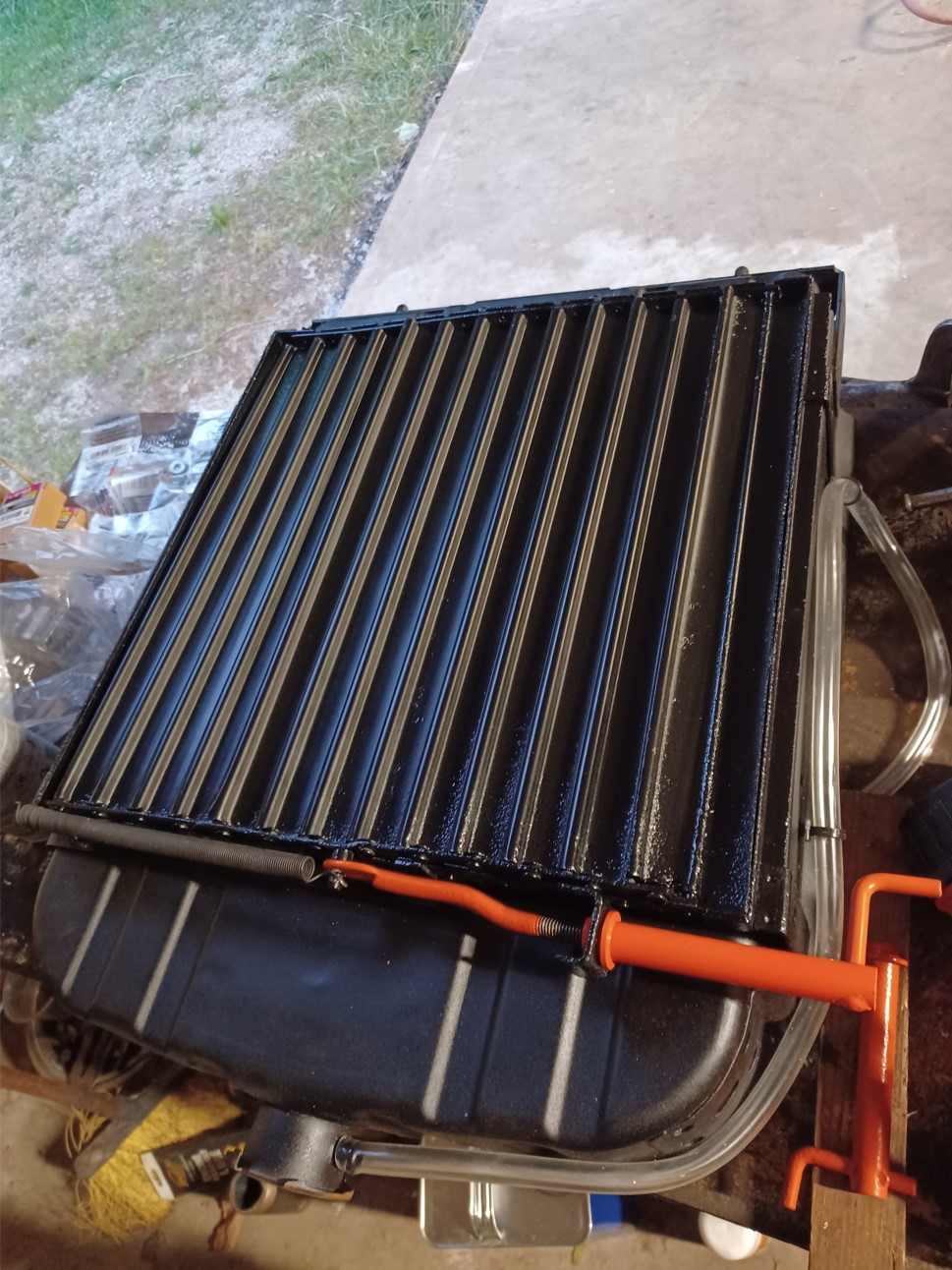
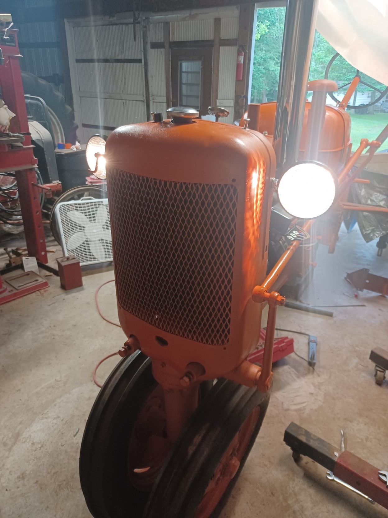
Sand blasted and made some minor repairs to the original shutters. They were in really good shape except for one torn hinge.
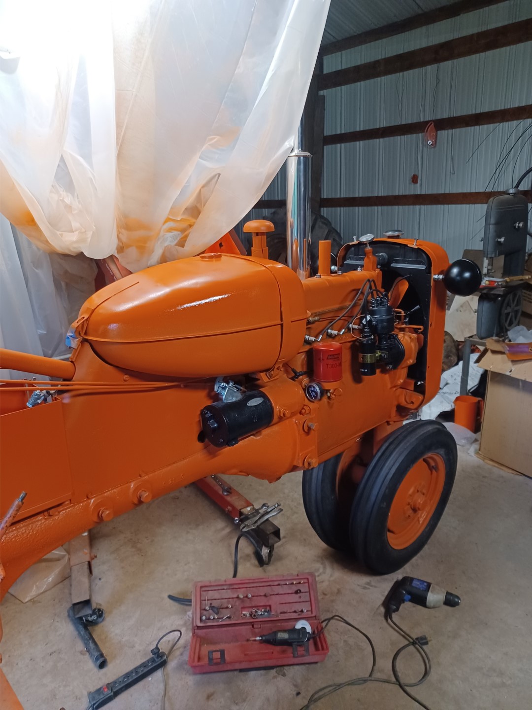
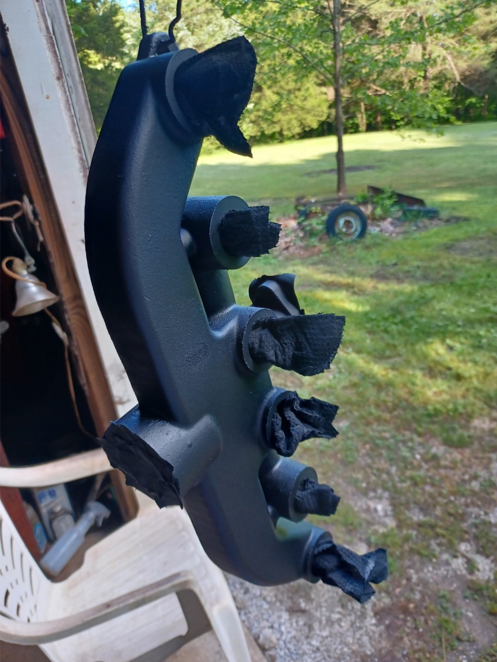
Installed. This pic also shows the aftermarket radiator overflow tube. The nipple sticks out way too far and the hose gets crushed by the cowling. I shortened it and routed a smaller diameter tube differently. I'm not quite happy with it and will probably improve it later. The original radiator has a deep recess in the top for the tubing. Again the aftermarket radiator shutter mounting holes didn't line up but was a simple hole size increase to fix adequately.
2000f paint on the new manifold.
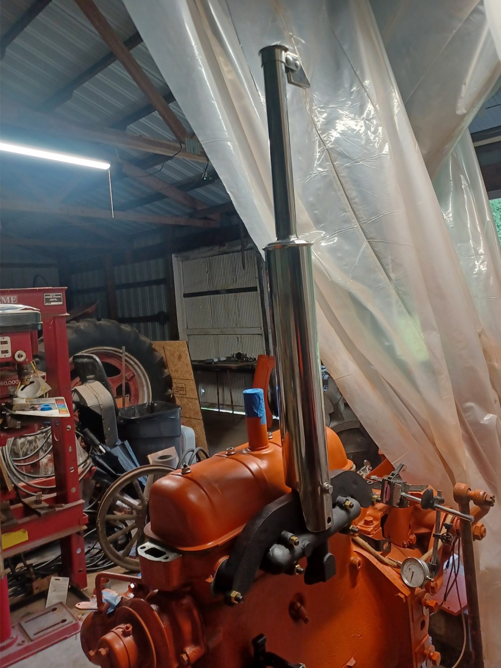
Manifold and muffler installed:
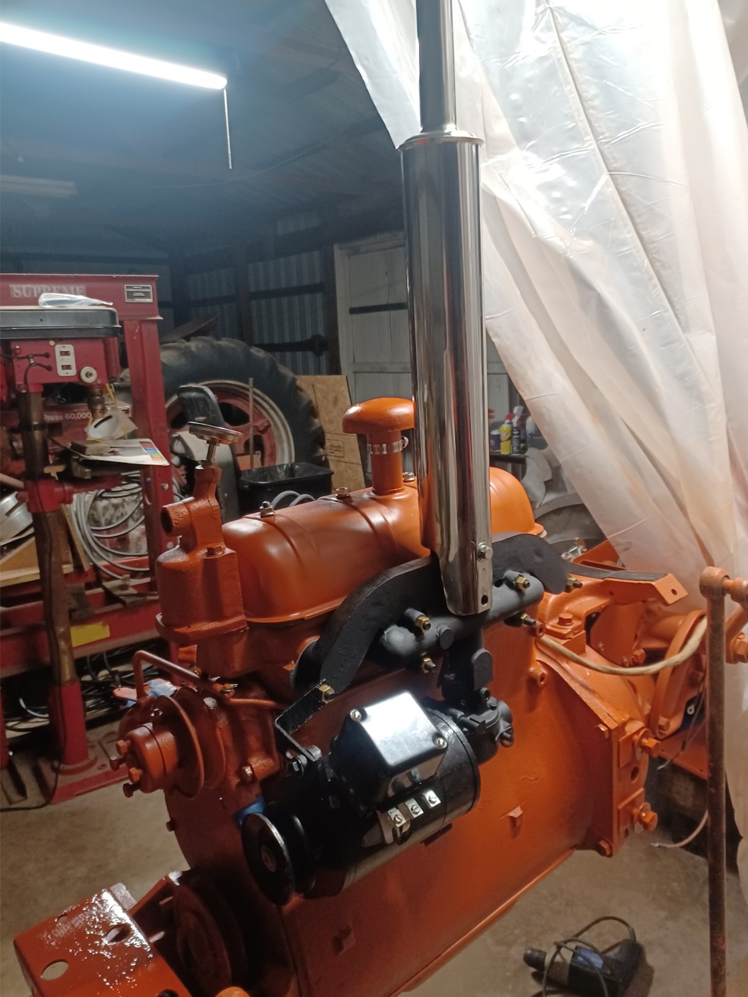
Rebuilt original generator with regulator and rebuilt carb installed:
The mounting holes in the aftermarket radiator (made in Turkey) for the cowling didn't match up. I had to increase the hole sizes for the bottom 2 holes (were 1/4 inch holes) to 3/8 inches and then had to slot the bottom holes because they still would not line up by 3/8 or so.
After reversing the radiator mounting plate to position the "hole reinforcement" towards the engine, the radiator fit properly. This is after I rewired and installed the lights and battery. I also had to clean up the threads on the large steering linkage on the lefthand side of the tractor. I then installed two new castle nuts.
Likewise, the hood was pretty beat up. I worked for hours trying to get it straight enough to avoid bondo, but failed. I don't have the nice body metal working tools there that I have at home. But I was running out of time so I'll consider further improvements in the future. The hood and radiator cowling were also welded up by a body shop due to various rips and tears around the mounting holes and the oil filler hole. The headlights were basically decapitated at some point. One could have been easily renovated but the second one would have taken quite a bit of effort (still doable), but I elected to get new ones.
I was running out of time so I elected to do a good enough for now effort on the tin. I can easily address that later. There is more functional work to be done first.
We were able to get the engine to fire and briefly run. It sounded really good, all 4 cylinders fired. However, there seems to be a fuel problem. I suspect my carb rebuild went astray somewhere. There was one jet I was unable to remove and replace, but it was nice and clean. Also, the new battery I installed was discharged when I bought it and self discharged overnight (I checked for leakage and didn't measure any). The behavior is kind of strange with the charger, but it is one of those "automatic" chargers. I just want a switch to select 6V and an ammeter to tell whether it's sending current in. Basically, at 100% charge it turns the engine over really well...for 2 revolutions then it can barely turn it to the next compression stroke. Charge it back up, you get 2 good revolutions then the same behavior. Put it on a load tester, shows good though. I don't trust the load tester. The guy at OReilly told me he's never sold a 6V battery before. I suspect it was in the back uncharged for years. After a full charge (100%), if I disconnect the charger, wait 30 seconds and restart the charging, it behaves as if self discharged. One time the charge indicated it started over at 13%, the next time at 70%. I don't trust the battery or the charger :(
I also had an issue with an aftermarket fuel bowl. It absolutely would not screw into the gas tank. Any of several 3/8 pipe fittings I had laying around worked fine and easily screwed in. I ended up having to buy a die and "fix" the threads. Even then, it wasn't really happy screwing in straight. But I finally got it to go in properly. I fear though next time I remove it to clean/replace the screen, I may not be able to get it back in straight.
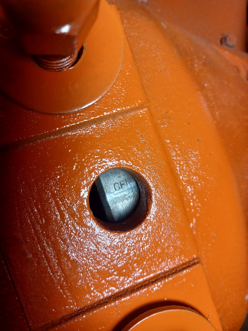
So, in working on the timing, we found the FIRE mark on the flywheel. Then we found a CENter mark just after the fire mark...then we found a second CENter mark. Are there two center marks??
Edited by dfwallis - 27 May 2024 at 10:42am
|
|
1952 CA13092, CA Pickup Plow, CA Cultivator, CA Two Row Planter, Dunham-Lehr GC78 Disc, Grader Blade, 3pt Fm180 Finish Mower
|
|
dfwallis
Orange Level
Joined: 09 Mar 2023
Location: DFW
Points: 949
|
Post Options
Thanks(0)
Quote Reply
Posted: 01 Jun 2024 at 11:19am |
|
I discovered that the paint I've been using (Tallman's) is actually made by Van Sickle. My substandard results are mostly my deficient painting environment and failure to add the hardener recommended. They also have a hard clear coat to add some more gloss. The paint itself isn't extremely glossy. The spray can version also refers to "flat" paint, but it clearly isn't flat. I've also been rushing it a bit to try to squeeze a huge amount of work in my short trips. I'm clearly not a painting expert, sadly.
|
|
1952 CA13092, CA Pickup Plow, CA Cultivator, CA Two Row Planter, Dunham-Lehr GC78 Disc, Grader Blade, 3pt Fm180 Finish Mower
|
|
dfwallis
Orange Level
Joined: 09 Mar 2023
Location: DFW
Points: 949
|
Post Options
Thanks(0)
Quote Reply
Posted: 30 Jun 2024 at 10:15am |
6/30/2024 Update: I removed the right rear axle to inspect the hand clutch and found it to be a basket case. Springs were loose and rolling around, 3 seats of some sort had fallen out (looks to be ball bearing seats but didn't check closely). My attempts to remove the clutch were not progressing using the pry bar method and unable to locate a puller with a 11.4 inch+ reach and rapidly running out of time, I elected to take it to the former AGCO dealer (successor to where it was purchased) and let them work on the clutch while I resumed prep of rear end parts for painting. A few days after I delivered it I actually did find a suitable puller, but the cost was a good chunk of what it will cost to have it repaired. I did make a homemade puller to try to add pressure while I used the pry bar, but the mild steel was bending under the strain.
The throw-out hub and bearing were both completely locked up, but they cleaned up nicely. The bearing was in excellent shape (given that it was probably not in contact with the clutch housing for 40 years). The adjusting hub/housing looked near new after I cleaned it up. I did need to clean up the threads to stop some binding, but nothing major. I think that the last time the clutch was worked on they just bolted the clutch plates together, but not verified...it may just be rusted fast.
I did get the engine running fairly well. The main issue initially was the throttle control wasn't applying enough force against the wrong carb throttle linkage spring (new one hadn't arrived yet) and it was just idling too slow to continue running. I also had to fix a weeping leak in the carb float bowl. The only remaining leak appears to be the oil drain plug.
Also, initially there was no oil pressure. This caused fear and dread :(, but I was able to prime the pump and got "good" pressure of 10psi at idle and up to 12psi at a slight rev.
I improved the battery cable ground connection. It appears I only THOUGHT about cleaning the paint off the connection (grounding was through the bolt head, but may as well get full surface contact). There's not much evidence that this improved the battery performance, but I think after the engine loosens up and I get it timed properly it will be fine.
I also verified that the new regulator was properly polarized and at the correct voltage before connecting.
Not wanting to fire up the compressor, I elected to use the drudgery method of wire brush and Dremel to clean up the seat spring and shock absorber. They cleaned up well and I got them primed but not painted. The shock absorber was still working reasonably well (pretty sure it's the original). I also removed and cleaned up the small, curved bracket on the seat mount arm.
I prepared the rockshaft and several other linkage parts and the tractor rear end housings for sand blasting. It appears that the poor tractor had been buried in mud up to the seat spring at some point. Caked on thick. Some of it didn't want to succumb to a chisel.
I welded up the right rear final drive oil pan and sealed it with epoxy and POR15 gas tank sealer. Primed and painted, ready to install. I then cleaned up the new rim and tire of all the leaked oil and sand blasting grime that got stuck in the oil.
I welded up the seat. This was a bit difficult because the metal was so thin. Kept burning new holes but I did get all of the cracked areas attached back together and then smoothed by grinding and epoxy. I had to grind off all around the edge. It was jagged and sharp. It's now less jagged and less sharp (but substantially all there).
I applied the bed liner material to the steering wheel. I didn't think the prior new paint finish would hold up very well. It turned out awesome. It looks great, nearly as good as a new one. I forgot to take pics this time, too busy trying to cram as much as possible into a week.
I installed a new 4 stage compressor air dryer on the wall and got it ready for use next trip. This makes 5 stages given the one just after the compressor. If it's still spitting a stream of water out after this, I'm gonna be upset :(
I was able to return the power director hitch-to-hydraulic pump control rod to its plunger hole. Hard to imagine how it got knocked out without doing any damage at all.
I installed a solar trickle charger to the front of the barn and soldered an extension cable to the too short solar panel cable and ran it across the rafters to drop down at the tractor. I bought another one for the garage for dad's 57 Thunderbird, but didn't get it installed yet.
I picked up my new suitcase weights from Fastenal. Four 70 lb weights. I think that will suffice for nearly anything I might want to do. I also got 2 front wheel weights.
Helped my brother unload the new 6-foot finish mower and tarped it.
Took measurements for my new tach sensor design. I'm thinking it will install at the bottom bell housing inspection hole and mount to that drop down loop just in front of it. Since that's probably intended as a "weep" hole, I'll need to consider that.
Edited by dfwallis - 30 Jun 2024 at 1:16pm
|
|
1952 CA13092, CA Pickup Plow, CA Cultivator, CA Two Row Planter, Dunham-Lehr GC78 Disc, Grader Blade, 3pt Fm180 Finish Mower
|
|
steve(ill)
Orange Level Access
Joined: 11 Sep 2009
Location: illinois
Points: 90921
|
Post Options
Thanks(0)
Quote Reply
Posted: 30 Jun 2024 at 1:28pm |
|
lots of work in the last 2-3 weeks !! Hope you got pictures so you can post when time permits !!
|
|
Like them all, but love the "B"s.
|
|
dfwallis
Orange Level
Joined: 09 Mar 2023
Location: DFW
Points: 949
|
Post Options
Thanks(0)
Quote Reply
Posted: 30 Jun 2024 at 6:00pm |
steve(ill) wrote:
lots of work in the last 2-3 weeks !! Hope you got pictures so you can post when time permits !!
|
Didn't get pics this week. It was mostly me getting filthy removing rust and grease and mud from various parts in prep for sand blasting. Saves a huge amount of blasting media if you get the 1/2" thick encrusted sections knocked off first. I got a brief first start and run clip I may put up, but even it is only about 1 second long.
|
|
1952 CA13092, CA Pickup Plow, CA Cultivator, CA Two Row Planter, Dunham-Lehr GC78 Disc, Grader Blade, 3pt Fm180 Finish Mower
|
|
steve(ill)
Orange Level Access
Joined: 11 Sep 2009
Location: illinois
Points: 90921
|
Post Options
Thanks(0)
Quote Reply
Posted: 30 Jun 2024 at 8:00pm |
|
I scrape the GUNK and dirt off first.. Sometimes pressure wash if needed for non flat areas.. Washer also takes off the green crud / alge stuff...... After that i needle gun as needed to get 50% of the rust off... Small parts go in the sand blaster after that.. I have not tried the " open air sand blast " method yet.. but do have a tank ready.
|
|
Like them all, but love the "B"s.
|
|
HudCo
Orange Level

Joined: 29 Jan 2013
Location: Plymouth Utah
Points: 4078
|
Post Options
Thanks(1)
Quote Reply
Posted: 30 Jun 2024 at 10:54pm |
|
looking real nice
|
|
dfwallis
Orange Level
Joined: 09 Mar 2023
Location: DFW
Points: 949
|
Post Options
Thanks(0)
Quote Reply
Posted: 01 Jul 2024 at 11:21am |
Not very interesting but here's 2 seconds of first start and run:
|
|
1952 CA13092, CA Pickup Plow, CA Cultivator, CA Two Row Planter, Dunham-Lehr GC78 Disc, Grader Blade, 3pt Fm180 Finish Mower
|
|
Sugarmaker
Orange Level
Joined: 12 Jul 2013
Location: Albion PA
Points: 8662
|
Post Options
Thanks(0)
Quote Reply
Posted: 04 Jul 2024 at 9:03pm |
dfwallis, Your doing a awesome job. Maybe I will get some inspiration to work on our CA too. Regards, Chris and Cheryl |
|
D17 1958 (NFE), WD45 1954 (NFE), WD 1952 (NFE), WD 1950 (WFE), Allis F-40 forklift, Allis CA, Allis D14, Ford Jubilee, Many IH Cub Cadets, 32 Ford Dump, 65 Comet, 66 F100.
|
|
dfwallis
Orange Level
Joined: 09 Mar 2023
Location: DFW
Points: 949
|
Post Options
Thanks(0)
Quote Reply
Posted: 04 Jul 2024 at 9:25pm |
Sugarmaker wrote:
dfwallis,Your doing a awesome job. Maybe I will get some inspiration to work on our CA too. Regards, Chris and Cheryl |
Thanks :) It's a bit challenging for me. I'm doing it by traveling a week here and a week there and cramming as much as I can fit in while I'm there. If AGCO gets the clutch rebuilt within a month or so, it looks good for having it working by the end of the year. I expect hydraulic pump issues, but not going to try it until I can get all the fluid changed out (already largely drained with some water present).
|
|
1952 CA13092, CA Pickup Plow, CA Cultivator, CA Two Row Planter, Dunham-Lehr GC78 Disc, Grader Blade, 3pt Fm180 Finish Mower
|
|
dfwallis
Orange Level
Joined: 09 Mar 2023
Location: DFW
Points: 949
|
Post Options
Thanks(0)
Quote Reply
Posted: 05 Jul 2024 at 3:24pm |
|
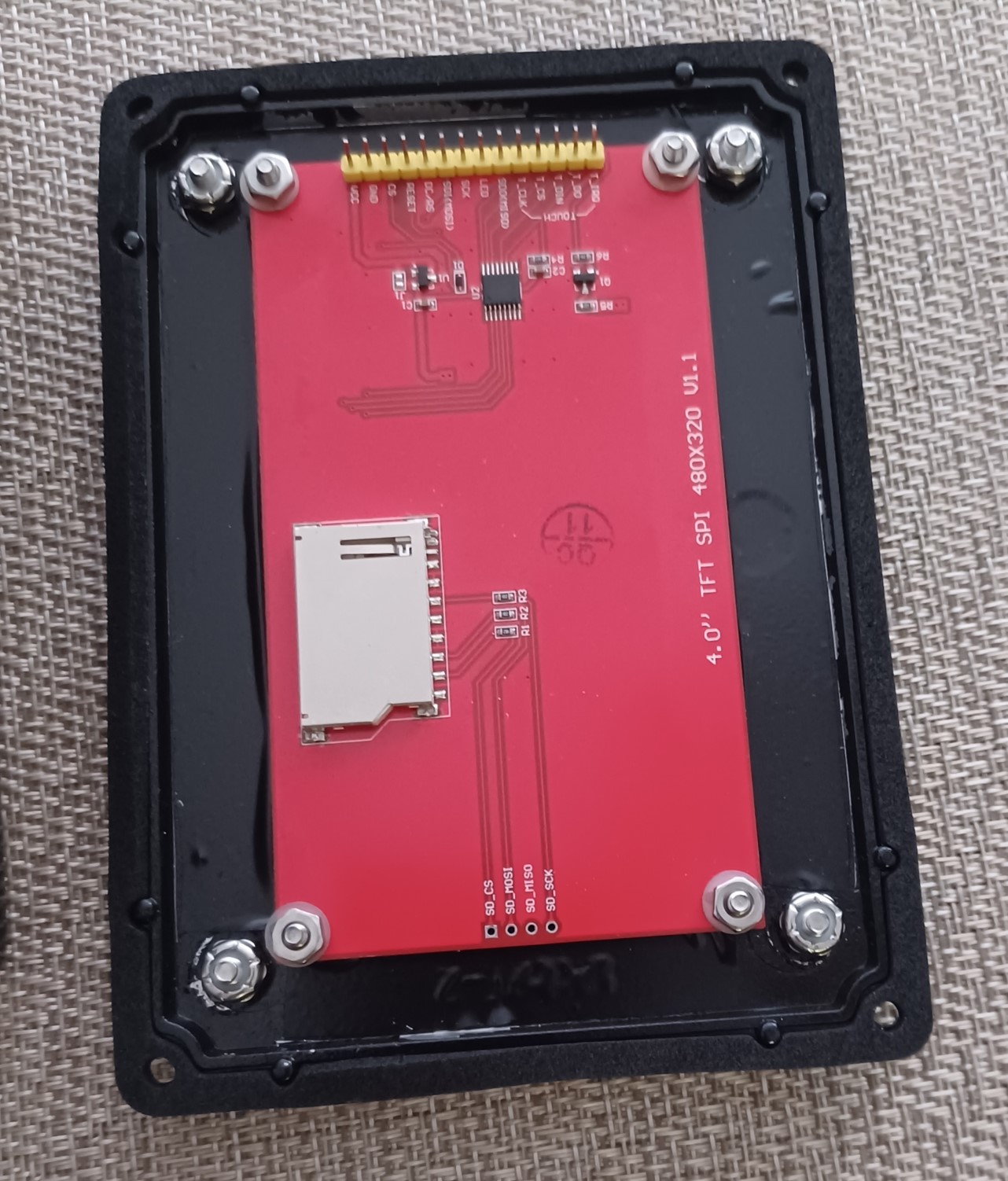
I had thought I had an extra Arduino Nano to use for the tachometer display project but it appears to be dead. It runs but won't communicate via the USB port. I discovered in testing that it doesn't have enough memory to operate the TFT display though, so I bought a new Nano ESP32 ($22). It's much faster (240Mhz vs 16Mhz) and has lots more memory. It also isn't so picky about the USB cable length. Another "advantage" is that it's 3.3V logic so I don't have to use voltage dividers to attach the display signals. I may have the software mostly done in a few hours. The hard part will be selecting the enclosures and connectors/wiring. I've a reasonably good design for the sensor attachment. I believe a simple plumbing T with short pipe insert(s) will work perfectly with a through-bolt end to end to mount it to the "loop" on the bottom of the bell housing. Then coat the flywheel edge flat black and a single white strip for the IR sensor signal.
|
|
1952 CA13092, CA Pickup Plow, CA Cultivator, CA Two Row Planter, Dunham-Lehr GC78 Disc, Grader Blade, 3pt Fm180 Finish Mower
|
|
dfwallis
Orange Level
Joined: 09 Mar 2023
Location: DFW
Points: 949
|
Post Options
Thanks(0)
Quote Reply
Posted: 13 Jul 2024 at 3:14pm |
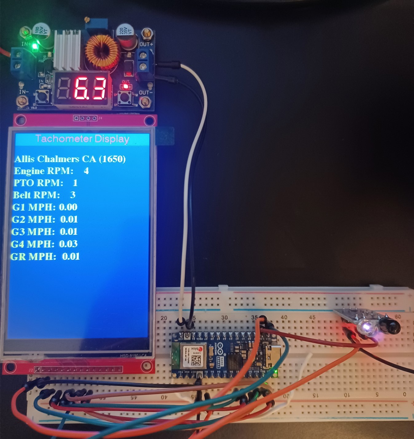
Tachometer project status 7/13/2024:
Code appears to be working. Took roughly a day. Most of the trouble was getting the Nano ESP32 pin references right. With the original nano, referencing the pin number directly worked fine. With the new ESP32, it seems to reference GPIO (internal processor) signals (sometimes). Resorting to using the pin variable names (e.g. D13 for pin 13) seemed to work in all cases. There is a setting in the IDE to change the pin reference to GPIO or PCB but I think there may be a bug somewhere for the Nano ESP32.
It doesn't really amount to much, just counts IR sensor pulses in a given time span and displays the results. All of the conversion factors are based on tractordata.com data so may or may not be accurate in every case.
As designed, it contains code for B, C, CA, WC, WD, WD45, WF, UC. The default is CA if none of the open/ground pins are grounded (4 pins to represent 4 bits so there is a little room for growth). I may or may not include a DIP switch to change the setting in the first one. Verified that it works ok on 6V and per the chip spec, down to 5.5V (of course all the logic is 3.3V).
I need to research whether I can control the TFT brightness. I think it's not controllable on this particular display (off or full brightness). I may program it to go to sleep after 10 seconds or so and wake up if the RPM value changes by some tolerance. I'd kind of like to avoid connecting the touch screen, but it may be necessary as an alternate "wake-up" signal. The ribbon cable for the TFT is on order.
I mostly completed the IR sensor to bell housing mount. I need to adjust the IR sensor sensitivity. New ones seem to be set to minimum which is about an inch from the sensor. That may be just a hair too short for the mounting position.
Of course, I still need to test the pulse count accuracy. It seems like the detection is very fast
I could also add a battery voltage sensor (have one already but it's 5V instead of 3.3V so I'd have to level shift and scale it). That might be handy. Edit: It's a simple voltage divider so I just limit the max input voltage (sense no more than 16.5V) and add a zener to clamp the output at 3.3V so as to try to not damage the Nano input if it exceeds the max sense for some reason.
After all that, then decide on (weatherproof) enclosure and faceplate. It will have an on/off switch as well. The cable will include a weatherproof disconnect at the sensor and at the CPU enclosure so they can be worked on independently. I'm thinking it will mount on the steering column but haven't decided.
The RPM below is how fast I waved a white ink pin in front of the sensor. I verified that a black ink pin doesn't cause a signal. I need to multiply it by 60 in this case (code fixed). I haven't decided on the best sampling method/time span, but I think a 1 second update rate will be ok.
Edited by dfwallis - 13 Jul 2024 at 3:54pm
|
|
1952 CA13092, CA Pickup Plow, CA Cultivator, CA Two Row Planter, Dunham-Lehr GC78 Disc, Grader Blade, 3pt Fm180 Finish Mower
|
|
Dakota Dave
Orange Level

Joined: 12 Sep 2009
Location: ND
Points: 3974
|
Post Options
Thanks(0)
Quote Reply
Posted: 13 Jul 2024 at 6:26pm |
|
I have a wish bone one that was on my pin hitch CA. It's now on my WD 45. It looks just like the snap coupler wishbone that has a tube welded to the snap coupler en's. To use on a snap coupler I pull the bell off and pin it in place. I got it from either Tony's tractor or OK tractor. I don't rember. It's a class 2 so it's heavy for the CA. But it works well. You just drop the pin hitch drawbar. Un pin the lift cylinders rotate the lift arms up and repin the cylinders. Put the same pin that held the hitch back in with the wishbone end in it's place. It'll lift way more than a CA should. Even with a loader on with the pallet forks and far too much wieght it would lift the front end off the ground
|
|
dfwallis
Orange Level
Joined: 09 Mar 2023
Location: DFW
Points: 949
|
Post Options
Thanks(0)
Quote Reply
Posted: 13 Jul 2024 at 7:02pm |
Dakota Dave wrote:
I have a wish bone one that was on my pin hitch CA. It's now on my WD 45. It looks just like the snap coupler wishbone that has a tube welded to the snap coupler en's. To use on a snap coupler I pull the bell off and pin it in place. I got it from either Tony's tractor or OK tractor. I don't rember. It's a class 2 so it's heavy for the CA. But it works well. You just drop the pin hitch drawbar. Un pin the lift cylinders rotate the lift arms up and repin the cylinders. Put the same pin that held the hitch back in with the wishbone end in it's place. It'll lift way more than a CA should. Even with a loader on with the pallet forks and far too much wieght it would lift the front end off the ground |
Didn't like the design of any I could find. Making my own out of a WD45 one.
|
|
1952 CA13092, CA Pickup Plow, CA Cultivator, CA Two Row Planter, Dunham-Lehr GC78 Disc, Grader Blade, 3pt Fm180 Finish Mower
|
|
dfwallis
Orange Level
Joined: 09 Mar 2023
Location: DFW
Points: 949
|
Post Options
Thanks(0)
Quote Reply
Posted: 14 Jul 2024 at 8:06pm |
Tachometer project status 7/14/2024:
I modified the pulse measurement approach slightly. Instead of counting pulses, I decided to just measure the time from leading edge to leading edge. I then sample 5 sets in a row and average those to reduce noise. This has the added benefit of being able to handle much higher pulse rates since it drops out of the loop as soon as a pulse transition occurs, ready for the next test. I tested with a 4800 rpm 1.5VDC motor and it appeared fairly accurate (as well as reading a 3x value when it detected each of the 3 fan blades...was surprised it was that fast). I may need to set up a more realistic test though to determine if 5 readings is enough to keep the noise down.
I also added the code for the battery voltage sensor, but I'm unable to find the one I thought I had so a new one is on order for tomorrow (another $5 down the drain). So I may have to tweak the resolution multiplier (changes one number) once I get the details/test of the one I ordered. Next task is to decide if I can dim or blank the display after a period of steady state operation and how/when to "wake up". That's the last software task that I plan, I think.
Edit: Researching the TFT display, it appears that the brightness can be controlled via an analog signal. Others require a PWM signal, some are not controllable. This doesn't necessarily change my approach, but I COULD fairly easily add a brightness control interface rather than just on/off.
Edited by dfwallis - 14 Jul 2024 at 9:16pm
|
|
1952 CA13092, CA Pickup Plow, CA Cultivator, CA Two Row Planter, Dunham-Lehr GC78 Disc, Grader Blade, 3pt Fm180 Finish Mower
|
|
dfwallis
Orange Level
Joined: 09 Mar 2023
Location: DFW
Points: 949
|
Post Options
Thanks(0)
Quote Reply
Posted: 15 Jul 2024 at 1:38pm |
|
Tachometer project status 7/15/2024: Code for LCD brightness control is complete. Turned out that it is controllable via PWM (not raw analog) which was a simple analog write to the discrete IO port. At present, it dims after 10 seconds and any RPM change of at least 100RPM will set it back to full brightness. I'll finish up the voltage sensor code later today when I receive the sensor (maybe no change).
|
|
1952 CA13092, CA Pickup Plow, CA Cultivator, CA Two Row Planter, Dunham-Lehr GC78 Disc, Grader Blade, 3pt Fm180 Finish Mower
|
|
dfwallis
Orange Level
Joined: 09 Mar 2023
Location: DFW
Points: 949
|
Post Options
Thanks(0)
Quote Reply
Posted: 15 Jul 2024 at 8:09pm |
Tachometer project status update 7/15/2024: Well, the best laid plans...looks like I'll have to make my own mounting bezel for the LCD. I can't find one the right size. Surely they make one. I've found a few that look close, but can't get the precise dimensions and some measure the size diagonally and some by active area. Not really a big deal, just a temporary road block.
Edit: Added benefit to making my own is that I can make it waterproof. I now have the enclosure, aluminum, and acrylic sheets for the faceplate...my goal for 7/17. I also decided to order a different PCB project board that fits the enclosure a little better than the one I have.
Edit: I decided that the plastic enclosure was not going to be adequately sturdy. Waiting on a metal enclosure. Additionally, the plastic enclosure was a bit bigger than desired. Plastic size choices are limited, but the metal one is much closer to the desired size. Should arrive by 7/24. I can reuse the faceplate as-is with the new enclosure.
Edited by dfwallis - 20 Jul 2024 at 8:31pm
|
|
1952 CA13092, CA Pickup Plow, CA Cultivator, CA Two Row Planter, Dunham-Lehr GC78 Disc, Grader Blade, 3pt Fm180 Finish Mower
|
|
dfwallis
Orange Level
Joined: 09 Mar 2023
Location: DFW
Points: 949
|
Post Options
Thanks(0)
Quote Reply
Posted: 25 Jul 2024 at 4:52pm |
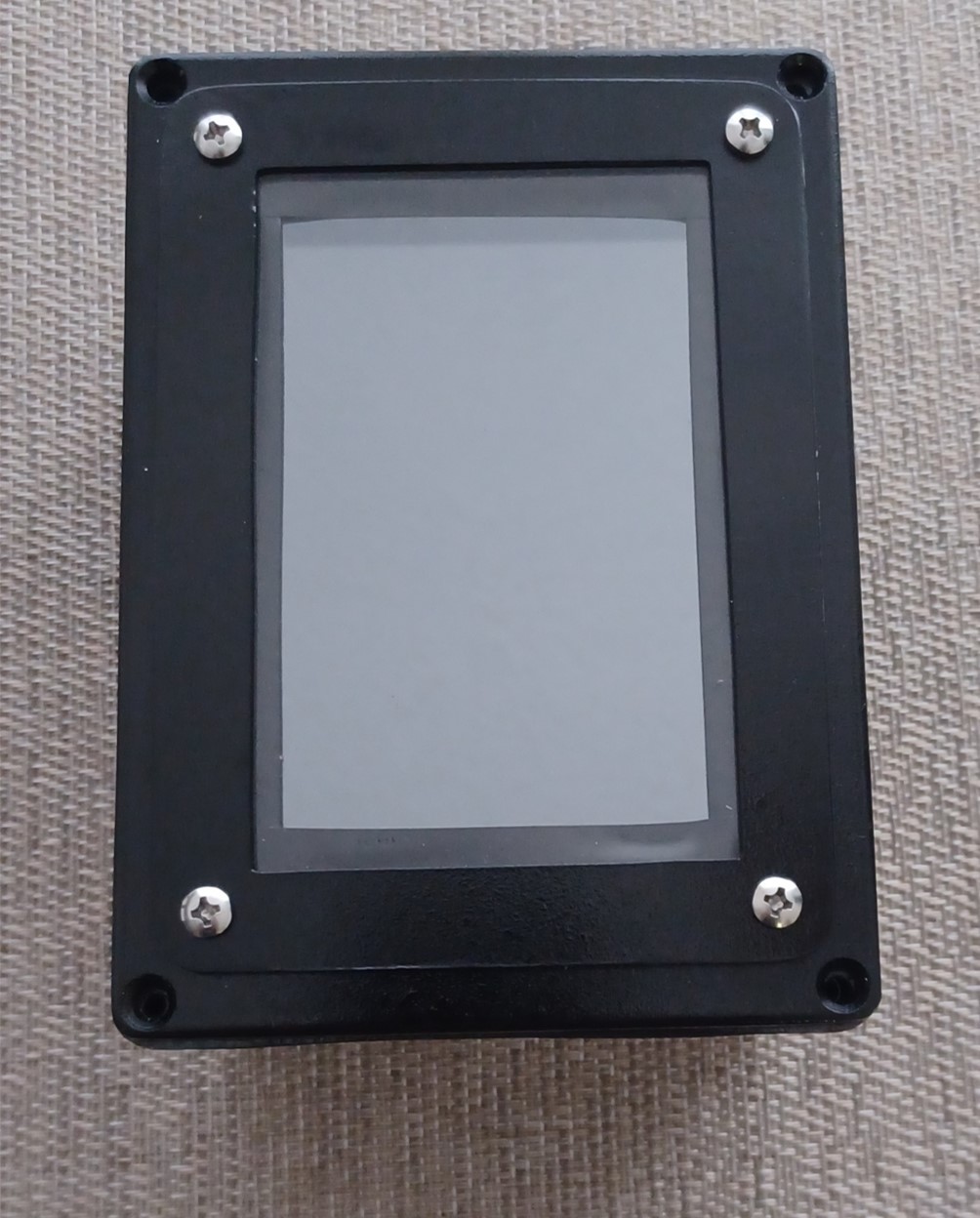
Tachometer project status update 7/25/2024:
Not a huge amount of (mechanical) progress but I have the TFT mounted in the enclosure faceplate. I either need to cut a gasket for underneath the acrylic window or I need to seal it around the edge. Because the faceplate is too flexible, it probably won't seal in the middle with a gasket, so I'm leaning towards black silicon seal around the edge. I guess I could add two more mounting screws in the center.
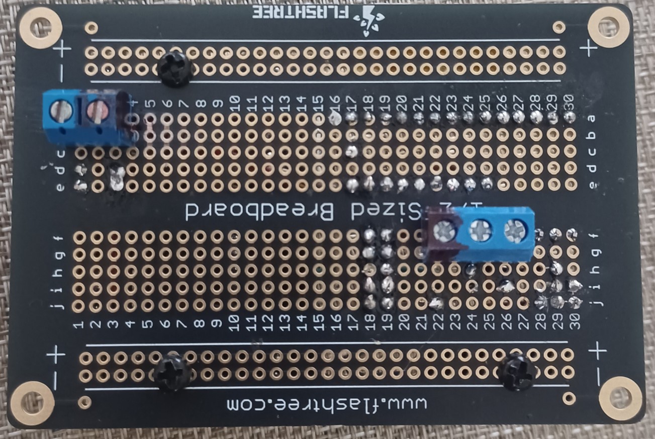
Mostly waiting on electrical parts which should arrive today and tomorrow. I need the PCB arrangement decided before I drill holes for switch, cables, and mount. The enclosure is an odd size. I didn't find any PCBs off the shelf designed to fit the mounting slides, but I found one that should be very close. I can always make a mounting tray though, no big deal if they don't fit quite right.
I did change the software display brightness dimmer timer to 20 seconds from 10 seconds. Ten seconds was a bit too annoying.
I also researched adding a hydraulic pressure sensor, but the sensor cost more than the entire project so far. Besides I already have a mechanical gauge.
My next trip is set for mid August. I enquired the (ex) AGCO dealer progress on my hand clutch rebuild. There was zero progress, hadn't even looked at it after 3 weeks (told me he'd look at it the following week after I left it). I'm getting the impression there's a lack of interest although he seemed fine and interested when I left it.
The black tape is a kludge to prevent the (metal) TFT sides from contacting the metal enclosure. I also applied some insulating glue. With a positive ground system and a negative ground TFT, who knows what might happen, maybe WWIII :(
Edit: just received the PCB and they fit perfectly so tomorrow I can decide on the internal arrangement and start wiring.
Edited by dfwallis - 25 Jul 2024 at 5:56pm
|
|
1952 CA13092, CA Pickup Plow, CA Cultivator, CA Two Row Planter, Dunham-Lehr GC78 Disc, Grader Blade, 3pt Fm180 Finish Mower
|
|
dfwallis
Orange Level
Joined: 09 Mar 2023
Location: DFW
Points: 949
|
Post Options
Thanks(0)
Quote Reply
Posted: 26 Jul 2024 at 4:43pm |
Tachometer project status update 7/26/2024:
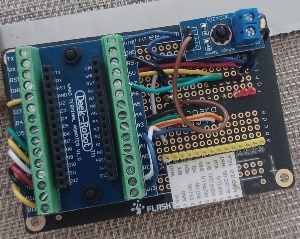
I've completed the enclosure parts arrangement design and drilled mounting, cabling, and switch holes. I believe I can get by with a single PCB by dispensing with the dedicated screw terminals for power and RPM sensor (they'll go to a screw terminal anyway on the Arduino breakout PCB).
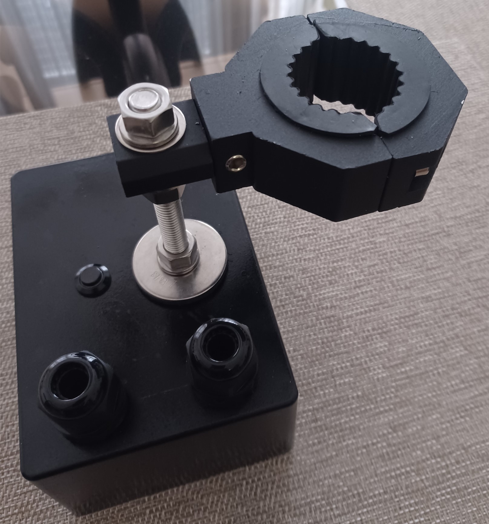
The clamp should nicely fit the steering column (I have different rubber insert sizes to try but I believe this is the correct one). Since the steering column is at an angle, the mount can be locked at any angle as well, but the detents are at 90 and 45 degrees. There will be a push button on/off switch (with blue illuminating ring), and there are two waterproof cable clamps. The large fender washers are to distribute the strain to a wider area. I was afraid the ABS enclosure wouldn't stand up to this mounting arrangement, so opted for a metal enclosure instead. It should meet IP6x weatherproofing requirements (resistant but not submersible). I'll probably need to seal the switch better, it seems substandard as-is, although claims IP6 rating. I'll probably include a silica packet inside as well.
Edited by dfwallis - 26 Jul 2024 at 4:49pm
|
|
1952 CA13092, CA Pickup Plow, CA Cultivator, CA Two Row Planter, Dunham-Lehr GC78 Disc, Grader Blade, 3pt Fm180 Finish Mower
|
|
dfwallis
Orange Level
Joined: 09 Mar 2023
Location: DFW
Points: 949
|
Post Options
Thanks(0)
Quote Reply
Posted: 31 Jul 2024 at 5:05pm |
Tachometer project status update 7/31/2024:
PCB wiring is complete barring test issues. Took quite a while to get all the parts. I made a last minute change to add an inline fuse. Not quite happy with the cable mess that resulted. I may improve that tomorrow. It was necessary for me to buy a heavy duty magnifying headset to finish the PCB. I just can't see anymore. Works really well, but the lenses are acrylic. Better not splash any parts cleaner fluids :( Only thing left before I ship it to dad's is to make the header connectors for the sensor itself. I'll make one end of the external cables (plug/sockets) but the other ends will depend on the routing (length) I decide when I install it, so I'll make those ends there.
Two header connectors on the PCB are for the TFT and the on/off switch. The external inputs (power and sensor) attach via the screw terminals on the bottom. This may not be the best mechanical approach, but I was trying to use on-hand parts as much as possible. I may make additional labeling improvements.
|
|
1952 CA13092, CA Pickup Plow, CA Cultivator, CA Two Row Planter, Dunham-Lehr GC78 Disc, Grader Blade, 3pt Fm180 Finish Mower
|
|