| Author |
 Topic Search Topic Search  Topic Options Topic Options
|
ac55tractor 
Silver Level

Joined: 20 Oct 2012
Location: Raymond, Maine
Points: 240
|
 Post Options Post Options
") Thanks(0) Thanks(0)
 Quote Quote  Reply Reply
 Topic: A/C B connecting rods "Rework" Topic: A/C B connecting rods "Rework"
Posted: 26 Dec 2021 at 8:58pm |
Last night I was saying, in a previous post, that I didn't think that anyone out there was stamping out new (or aftermarket) connecting rods for my A/C B.
Tonight, I found some aftermarket connecting rods. There is a place in New York state that has them.
Now, I stand corrected. 4 of them are $199.23 delivered. At that price, I
am going to try and repair the ones that I have. At least I have some
replacements that I can fall back on if I make a mistake. I
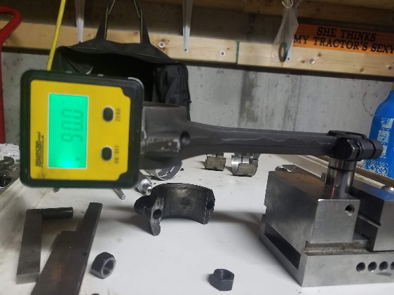
started looking over one of my rods today. So far, so good, I placed a
wrist pin in a precision vice, I clamped the connecting rod to the pin. I
zeroed out my protractor on the vice, and started checking for
squareness and twist.
I measured the center line distance between the wrist pin, and the bearing bore.
It is, 6 1/2 inches. Then I realized just how straight these rods must be.
If
by chance a connecting rod is tilted off to the side 1 tenth of one
degree. The piston will be tilted .011 in relationship to the
crankshaft. I'm sure that you understand the rest.
I will post updates when I can.
Steve from Maine 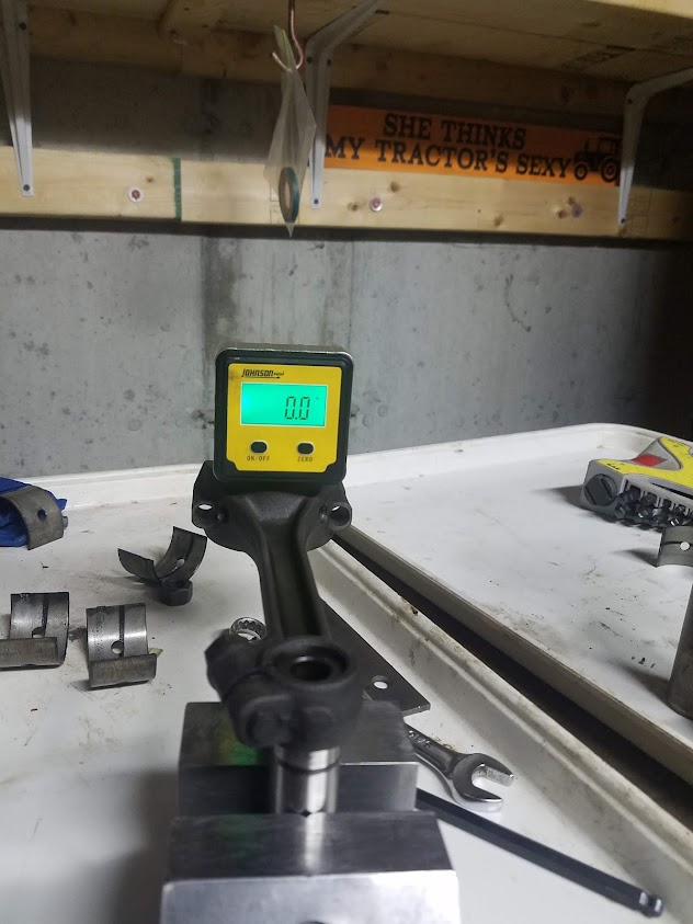
|
 |
|
Sponsored Links
|
|
|
ac55tractor
Silver Level
Joined: 20 Oct 2012
Location: Raymond, Maine
Points: 240
|
Post Options
Thanks(0)
Quote Reply
Posted: 26 Dec 2021 at 8:59pm |
|
|
|
ac55tractor
Silver Level
Joined: 20 Oct 2012
Location: Raymond, Maine
Points: 240
|
Post Options
Thanks(0)
Quote Reply
Posted: 29 Dec 2021 at 5:06pm |
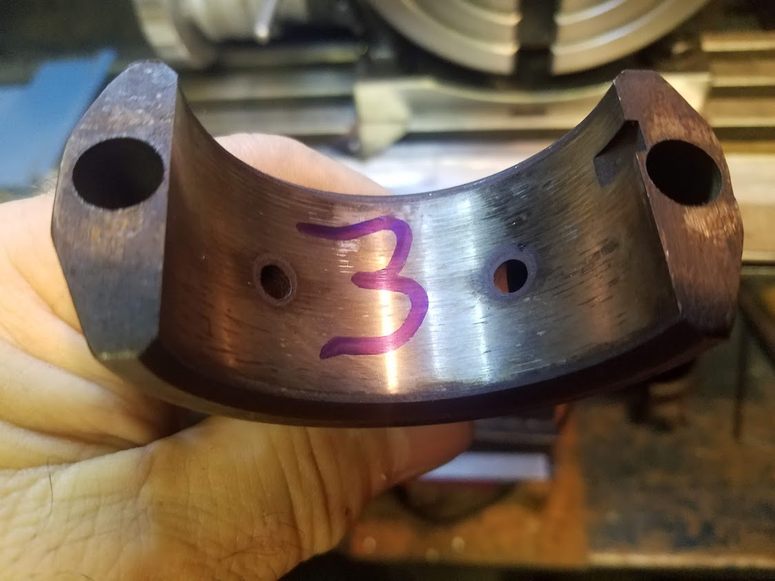
I checked over the connecting rods, I wrote down all of the dimensions. I started to get the caps and rods ready to re-qualify the bearing bores without shims. I looked at the mating surfaces and clearly, they were not making any substantial contact with each other. See near the bolt holes. The shiny spots are where contact was made. The other reason why I took the flats to clean is that the original measurements showed that the bores were egged. Now they are closer to round.
|
|
ac55tractor
Silver Level
Joined: 20 Oct 2012
Location: Raymond, Maine
Points: 240
|
Post Options
Thanks(0)
Quote Reply
Posted: 29 Dec 2021 at 5:09pm |
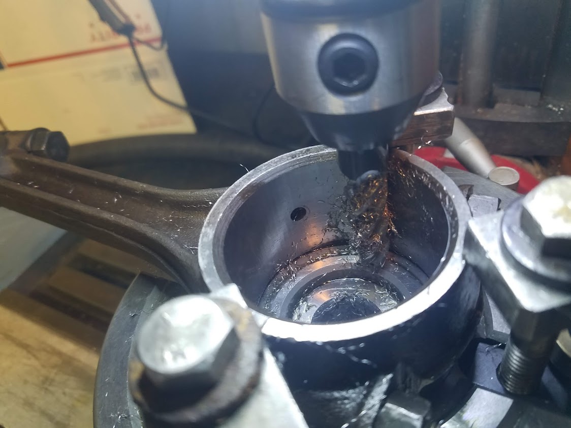
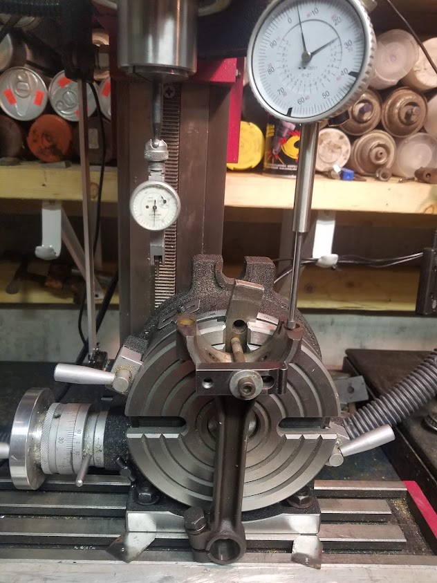
I set up the rotary table and mounted connecting rod#1. I
ran dial indicators over the part and aligned it to the machine.
|
|
ac55tractor
Silver Level
Joined: 20 Oct 2012
Location: Raymond, Maine
Points: 240
|
Post Options
Thanks(0)
Quote Reply
Posted: 29 Dec 2021 at 5:12pm |
I
took a fly cutter tool and touched off the top of the flat and removed as
little as possible to take it to clean. So far .003 - .005 is being removed. 
|
|
ac55tractor
Silver Level
Joined: 20 Oct 2012
Location: Raymond, Maine
Points: 240
|
Post Options
Thanks(0)
Quote Reply
Posted: 29 Dec 2021 at 5:13pm |
|
|
|
ac55tractor
Silver Level
Joined: 20 Oct 2012
Location: Raymond, Maine
Points: 240
|
Post Options
Thanks(0)
Quote Reply
Posted: 29 Dec 2021 at 5:15pm |

I measured the 1/2 bore. Then repeat.
In the process of cutting the mating surfaces
and re-qualify the bearing bore.
|
|
ac55tractor
Silver Level
Joined: 20 Oct 2012
Location: Raymond, Maine
Points: 240
|
Post Options
Thanks(0)
Quote Reply
Posted: 29 Dec 2021 at 5:16pm |
|
Please feel
free to ask any questions. I will be asking some of my own soon.
|
|
ac55tractor
Silver Level
Joined: 20 Oct 2012
Location: Raymond, Maine
Points: 240
|
Post Options
Thanks(0)
Quote Reply
Posted: 30 Dec 2021 at 10:16am |
I felt that I needed to add some clarity to this post.
I was installing new -.010 bearings to the connecting rods from my A/C B. For some reason the bearings would not fit the reground crankshaft. I spent a few days trying to figure out how to get them assembled.
That's when I turned to the forum. With the advice that I received, it became clear that the bearing bores on the connecting rods somehow became egg shaped in a way that could not be corrected without re-machining them. Adding shim to the parting line would not correct the error.
I am a life long Machinist, so reworking the rods is the easy part for me, and I could save a few bucks in the process.
In appreciation to the forum, I am taking pictures and sharing my progress with everyone.
Steve
|
|
steve(ill)
Orange Level Access

Joined: 11 Sep 2009
Location: illinois
Points: 88586
|
Post Options
Thanks(0)
Quote Reply
Posted: 30 Dec 2021 at 10:22am |
|
Steve, in addition to the rods, please show the rod clamp method, the milling head and boring bar as you do the work........ we would be interested in all parts of the job.
|
|
Like them all, but love the "B"s.
|
|
ac55tractor
Silver Level
Joined: 20 Oct 2012
Location: Raymond, Maine
Points: 240
|
Post Options
Thanks(0)
Quote Reply
Posted: 30 Dec 2021 at 10:44am |
Sure, I will show every thing as I go.
I really cannot bore with my mini mill yet. I have to build and install an attachment plate to the back of the machine to make it rigid enough to bore with. In a way it's a flaw in the design of the machine.
So for this job, I am going to set the rods up on the rotary table and mill the bore diameters round with a carbide endmill. It will be faster this way and a lot easier to control the diameters as I go. I have a new dial bore gauge coming in today to measure the diameters.
|
|
steve(ill)
Orange Level Access
Joined: 11 Sep 2009
Location: illinois
Points: 88586
|
Post Options
Thanks(0)
Quote Reply
Posted: 30 Dec 2021 at 12:41pm |
I am going to set the rods up on the rotary table and mill the bore diameters round with a carbide endmill.
well, i dont think i have ever seen that done before, but it should work ! setup will be critical... Your going to do how much ... .005 ?
Edited by steve(ill) - 30 Dec 2021 at 12:43pm
|
|
Like them all, but love the "B"s.
|
|
ac55tractor
Silver Level
Joined: 20 Oct 2012
Location: Raymond, Maine
Points: 240
|
Post Options
Thanks(0)
Quote Reply
Posted: 30 Dec 2021 at 2:38pm |
Yes, I am cleaning and squaring up the parting line by .002 - .003 on each cap and rod. When bolted together, prior to milling out the bore, the diameter of the bearing bore will be under-size roughly -.005.
The distance across the parting line was already roughly .005 under-size.
As I am cutting, I will be removing an almost equal amount all the way around the inside of the bore.
The plan is to mill out the bore to 2.059 to 2.060.
A 2.059 milled diameter, minus .130 for the thickness of 2 bearings = 1.929. The dimension of the crankshaft connecting rod journal is 1.927. When finished I will have a round bearing bore with .002 clearance for the bearings.
|
|
ac55tractor
Silver Level
Joined: 20 Oct 2012
Location: Raymond, Maine
Points: 240
|
Post Options
Thanks(0)
Quote Reply
Posted: 30 Dec 2021 at 4:53pm |
I just got the dial bore gauge set up. I assembled a rod and
cap. The inside diameter landed as planned. It is -.005 top to bottom and
-.0045 across the parting line. The bore is practically round. It measures
2.024 diameter.
|
|
BrianC
Orange Level Access
Joined: 16 Jun 2011
Location: New York
Points: 1619
|
Post Options
Thanks(1)
Quote Reply
Posted: 30 Dec 2021 at 5:19pm |
Previous post you said you were wanting to machine to 2.059 diameter. Also said after touching off the rod and cap ends, it should be roughly .005 under size. To me that means the diameter should be 2.054. However your last post says
it measures 2.024 diameter. Seems like a big difference between your estimate and actual, am I missing something?
It seems after skimming the rod and cap ends total of .005 and removing the original .010 shim, it should be .015 under size one direction, just about finished along the split line.
|
|
ac55tractor
Silver Level
Joined: 20 Oct 2012
Location: Raymond, Maine
Points: 240
|
Post Options
Thanks(0)
Quote Reply
Posted: 30 Dec 2021 at 5:35pm |
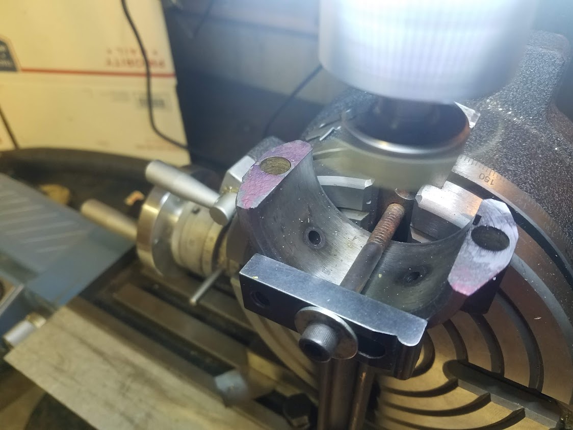
Here is an old Machinist trick that I learned from an old Machinist. See the pin inside the right side jaw (movable jaw) If you have a part and your sides are not exactly parallel, placing a pin in the movable jaw, in the right place will align the part to the vice and the machine. It is critical when machining these parts that the existing bores are parallel to the parting line flats and square or (perpendicular) to the same side on both parts (cap and rod) when assembled. I ran the indicator in and out inside every bore to make sure that they were square to the the solid jaw edge, and the height of the flats on the cap were the same before I cut the parting line flats. I did the same with the rods when they were mounted to the rotary table when I cut them.
So now when they are assembled the bore will be square to the same side of the rod and cap. That side will be placed down onto the rotary table. 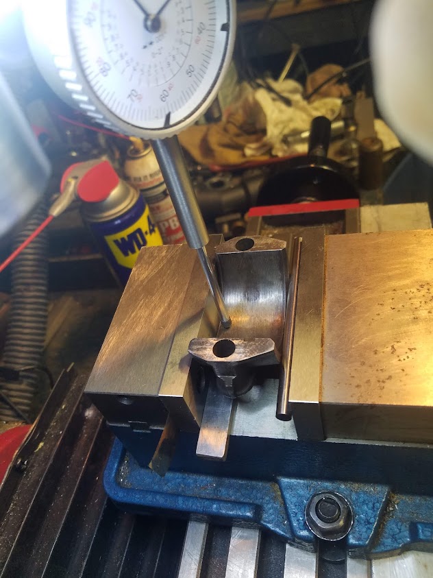
|
|
ac55tractor
Silver Level
Joined: 20 Oct 2012
Location: Raymond, Maine
Points: 240
|
Post Options
Thanks(0)
Quote Reply
Posted: 30 Dec 2021 at 5:46pm |
The 2.024 was a typo. Should have typed 2.054. Good eye there Brian.
I cannot explain anything about any previous shimming. We all know that these rods were shimmed at one time. I am going by what is there now for dimensions, not what was supposed to be there. I am trying to make what I have work. Please keep this in mind, these rods were egged so that the parting lines were small and the rod bore from top to bottom. I don''t have the dimensions in front of me at the moment (laptop is down cellar) but the dimension opposite the parting lines were oversize.
|
|
IBWD MIke
Orange Level

Joined: 08 Apr 2012
Location: Newton Ia.
Points: 4136
|
Post Options
Thanks(0)
Quote Reply
Posted: 30 Dec 2021 at 7:12pm |
I hate to say this but I think your over thinking this. These engines have run for 70+ years with the shims. Yes, it's nice to not have them but they worked with them just fine.
On my WD45 rebuild I used rods from a 45, no shims. WD rods have them. I did obsess over the main bearing clearance a bit. Made a lot of shims until I got the clearance where I wanted it.
|
|
ac55tractor
Silver Level
Joined: 20 Oct 2012
Location: Raymond, Maine
Points: 240
|
Post Options
Thanks(0)
Quote Reply
Posted: 30 Dec 2021 at 7:22pm |
I got the laptop, I am looking rod #2 at random .
The #2 bearing bore was 2.055 diameter across the parting line, it measured 2.059 diameter top to bottom. These dimensions were taken without shims.
If standard bearings were installed and the bore was round, without shims, the 2.059 dimension is within factory spec.
2.059 minus .120 (the thickness for 2 standard bearings) = 1.939 or .002 over the standard journal diameter of 1.937. So from what I can tell the bores top to bottom, were to size already without shim. I noticed this two weeks ago, but I didn't take the time to do the math until just now.
The undersize parting line brought me to where I am today reworking the rods. With new bearings installed, The rod would not move on the crank shaft. even with .010 shims.
If the bores were ok to begin with, I would be finished with the lower end of the engine by now.
This forum page may clear things up. please read through.
I felt oblagated to show what I was doing because of the help that I recieved from the forum. I have no idea what was done in the past. But these are the dimentions that I recorded as I disassembled. How it ran with an undersized bearing bore dimention on every parting line with an .008 shim on one side is beyond me. I am trying to correct what I have in front of me.
|
|
Les Kerf
Orange Level
Joined: 08 May 2020
Location: Idaho
Points: 1388
|
Post Options
Thanks(0)
Quote Reply
Posted: 31 Dec 2021 at 6:19am |
 ac55tractor wrote: ac55tractor wrote:
...The distance across the parting line was already roughly .005 under-size.
... |
Standard practice on modern REALLY HIGH performance engines is to squeeze the rod/cap assembly with a c-clamp at the parting line prior to final honing; this results in the bore being as much as 0.007" over-size at the parting line. This is done to compensate for the tendency of the rod cap to flex inward under the extreme stress loading at high rpm. I am puzzled as to how the rods on a presumably stock model B/C engine ever got into the shape that you have measured.  Thank you for posting your excellent photos and detailed description of your project 
|
|
ac55tractor
Silver Level
Joined: 20 Oct 2012
Location: Raymond, Maine
Points: 240
|
Post Options
Thanks(1)
Quote Reply
Posted: 31 Dec 2021 at 9:36am |
I can't speak for everyone, I think that most people who have seen this post and my previous post were puzzled by the condition of the rods. (see link above) You would think, if all the engines were manufactured the same, and all shimmed the same, at the factory, the reassembly process should be the same. I am a machinist, not an engine builder. I knew that I had the correct replacement parts and they were not going together.
That's when I started measuring the parts, more than once. I documented the dimensions. Things were not adding up and I could not understand what I found, so I presented the results to the forum. I got some real common sense replies to clearly a unique problem.
I am making something good out of some distorted parts, and I feel good about it. The main bearing bores are all shimmed. They measure round, and have the correct dimensions.
|
|
steve(ill)
Orange Level Access
Joined: 11 Sep 2009
Location: illinois
Points: 88586
|
Post Options
Thanks(0)
Quote Reply
Posted: 31 Dec 2021 at 9:46am |
|
IF you think about it, the rod goes up and down in the engine, changing directions 3200 times per minute... That MAY cause distortion of the rod.. If the rod was to "distort", you would think it would be in the direction of travel... and "possibly" shrink in the cross section thru the clamp area....Your only talking about 2-3 THOUSANDTHS, so it dont take a lot of flex............... this could also happen if the crank was only turned .009 undersize instead of .010 , or if the bearing shells were a couple thousands thicker than assumed.... but i think you have done a good job of discounting those possibilities, so the only think left is that the rod distorted lengthwise under LOAD..
|
|
Like them all, but love the "B"s.
|
|
ac55tractor
Silver Level
Joined: 20 Oct 2012
Location: Raymond, Maine
Points: 240
|
Post Options
Thanks(0)
Quote Reply
Posted: 31 Dec 2021 at 10:01am |
|
Connecting rod distortion was mentioned in all sorts of websites. Sometimes you have to Google the right question. It's clearly not a nitro powered funny car. But apparently the same distortion is possible in a 4 cylinder, low horsepower, low RPM Allis tractor engine.
|
|
Les Kerf
Orange Level
Joined: 08 May 2020
Location: Idaho
Points: 1388
|
Post Options
Thanks(0)
Quote Reply
Posted: 31 Dec 2021 at 10:26am |
ac55tractor wrote:
Connecting rod distortion was mentioned in all sorts of websites. Sometimes you have to Google the right question. It's clearly not a nitro powered funny car. But apparently the same distortion is possible in a 4 cylinder, low horsepower, low RPM Allis tractor engine.
|
Yup. Apparently they are weaker than I thought. From your excellent photos and description it appears that someone filed the mating surfaces down by hand, and also did not get things back in place correctly. The shims installed on only one side is odd. I will keep all of this in mind when I get around to overhauling my WD. Edit: The other important point is the fact that this engine ran for 30-some years like this 
Edited by Les Kerf - 31 Dec 2021 at 10:40am
|
|
ac55tractor
Silver Level
Joined: 20 Oct 2012
Location: Raymond, Maine
Points: 240
|
Post Options
Thanks(0)
Quote Reply
Posted: 31 Dec 2021 at 2:45pm |
All set up, ready to cut. All of the rod bores are now .005 undersized from the finish diameter. Everything fell into place. 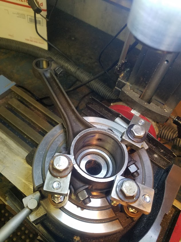
|
|
ac55tractor
Silver Level
Joined: 20 Oct 2012
Location: Raymond, Maine
Points: 240
|
Post Options
Thanks(0)
Quote Reply
Posted: 31 Dec 2021 at 5:45pm |
|
|
|
ac55tractor
Silver Level
Joined: 20 Oct 2012
Location: Raymond, Maine
Points: 240
|
Post Options
Thanks(0)
Quote Reply
Posted: 31 Dec 2021 at 5:46pm |
Diameter is right on the money. 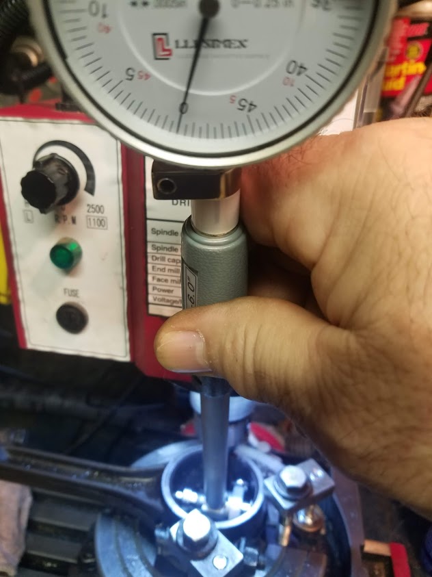
|
|
ac55tractor
Silver Level
Joined: 20 Oct 2012
Location: Raymond, Maine
Points: 240
|
Post Options
Thanks(0)
Quote Reply
Posted: 31 Dec 2021 at 5:47pm |
I'm very happy with the finish on the bore. 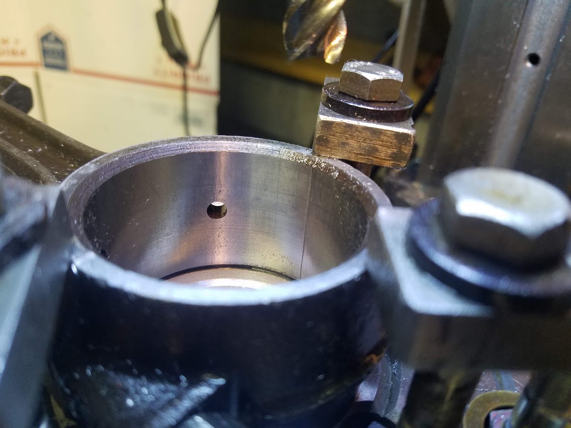
|
|
steve(ill)
Orange Level Access
Joined: 11 Sep 2009
Location: illinois
Points: 88586
|
Post Options
Thanks(0)
Quote Reply
Posted: 31 Dec 2021 at 6:36pm |
looks great..... .0025 cut should be a piece of cake for a good machinist !  
i have never seen a mill used to cut a bore like that.... Will keep it in mind !
Edited by steve(ill) - 31 Dec 2021 at 6:38pm
|
|
Like them all, but love the "B"s.
|
|
ac55tractor
Silver Level
Joined: 20 Oct 2012
Location: Raymond, Maine
Points: 240
|
Post Options
Thanks(0)
Quote Reply
Posted: 31 Dec 2021 at 6:42pm |
|
Thank you Steve. I don't think that I could have gotten better guidance from anywhere else.
|
|