A/C B connecting rods "Rework"
Printed From: Unofficial Allis
Category: Allis Chalmers
Forum Name: Farm Equipment
Forum Description: everything about Allis-Chalmers farm equipment
URL: https://www.allischalmers.com/forum/forum_posts.asp?TID=185349
Printed Date: 06 Nov 2025 at 6:44pm
Software Version: Web Wiz Forums 11.10 - http://www.webwizforums.com
Topic: A/C B connecting rods "Rework"
Posted By: ac55tractor
Subject: A/C B connecting rods "Rework"
Date Posted: 26 Dec 2021 at 8:58pm
|
Last night I was saying, in a previous post, that I didn't think that anyone out there was stamping out new (or aftermarket) connecting rods for my A/C B. Tonight, I found some aftermarket connecting rods. There is a place in New York state that has them. Now, I stand corrected. 4 of them are $199.23 delivered. At that price, I
am going to try and repair the ones that I have. At least I have some
replacements that I can fall back on if I make a mistake.
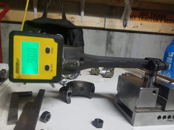
I
started looking over one of my rods today. So far, so good, I placed a
wrist pin in a precision vice, I clamped the connecting rod to the pin. I
zeroed out my protractor on the vice, and started checking for
squareness and twist. I measured the center line distance between the wrist pin, and the bearing bore. It is, 6 1/2 inches. Then I realized just how straight these rods must be. If
by chance a connecting rod is tilted off to the side 1 tenth of one
degree. The piston will be tilted .011 in relationship to the
crankshaft. I'm sure that you understand the rest. I will post updates when I can. Steve from Maine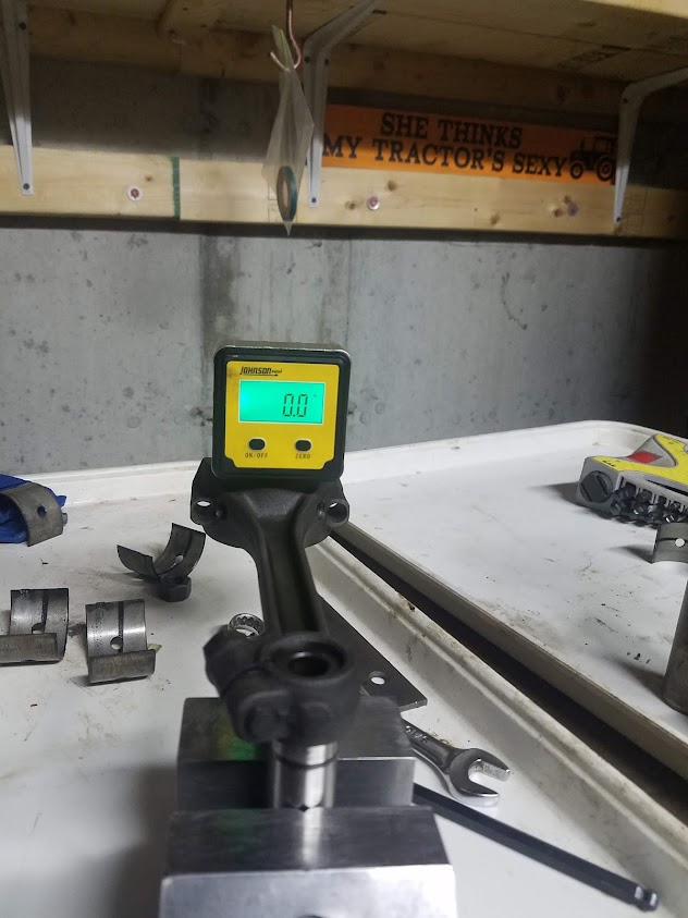 |
Replies:
Posted By: ac55tractor
Date Posted: 26 Dec 2021 at 8:59pm
|
Posted By: ac55tractor
Date Posted: 29 Dec 2021 at 5:06pm
|
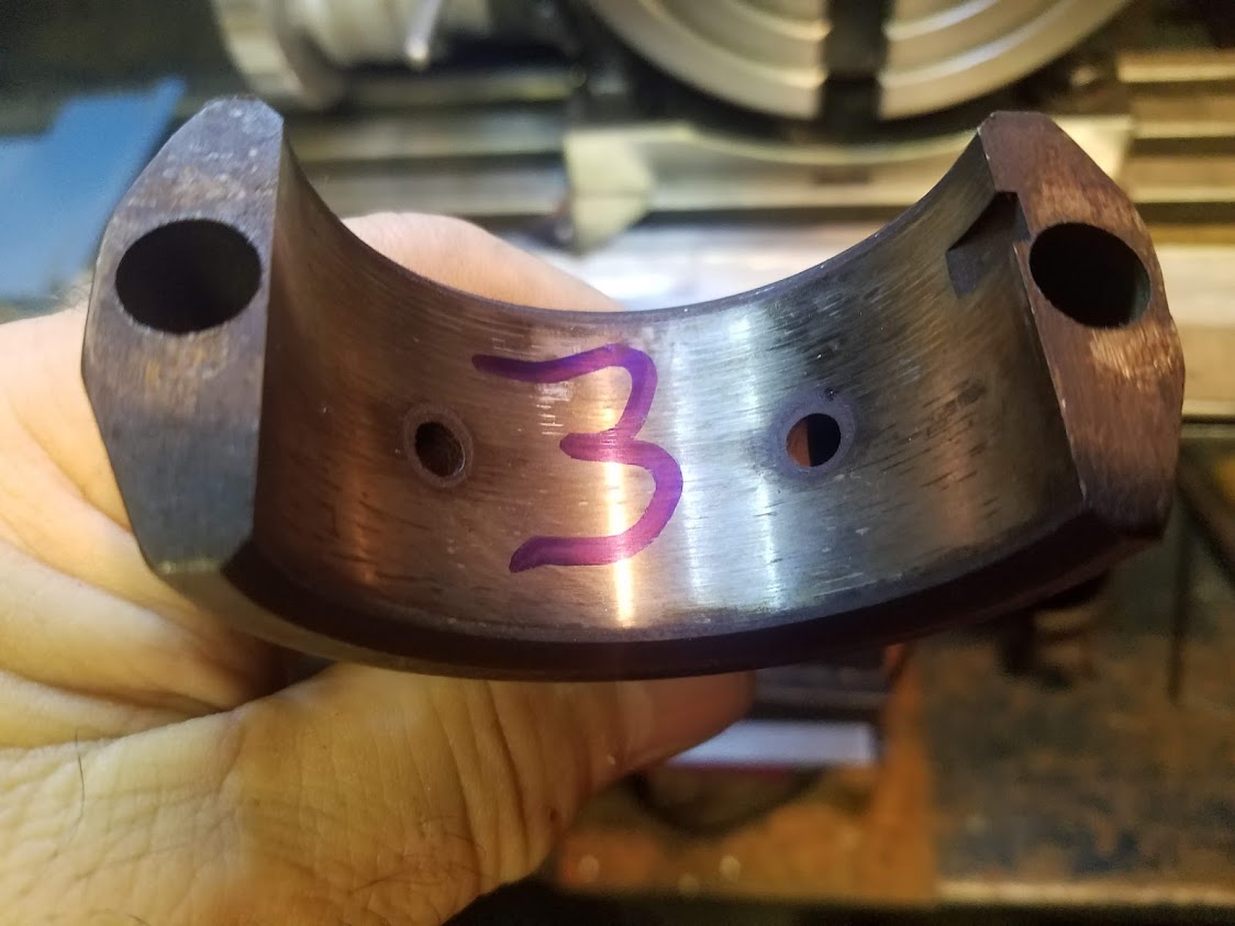
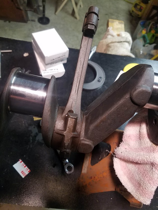
I checked over the connecting rods, I wrote down all of the dimensions. I started to get the caps and rods ready to re-qualify the bearing bores without shims. I looked at the mating surfaces and clearly, they were not making any substantial contact with each other. See near the bolt holes. The shiny spots are where contact was made. The other reason why I took the flats to clean is that the original measurements showed that the bores were egged. Now they are closer to round.
 |
Posted By: ac55tractor
Date Posted: 29 Dec 2021 at 5:09pm
|
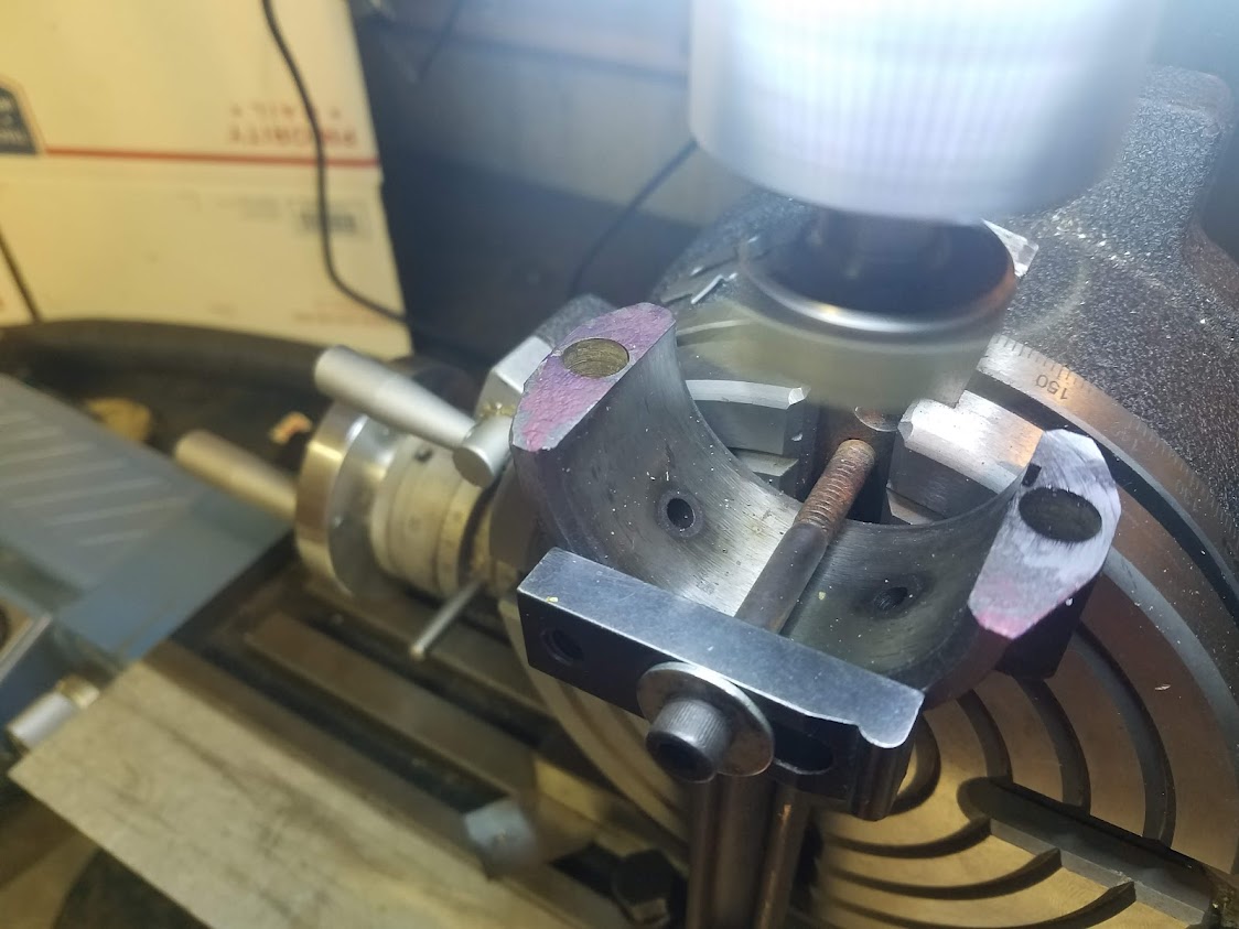
I set up the rotary table and mounted connecting rod#1. I ran dial indicators over the part and aligned it to the machine. 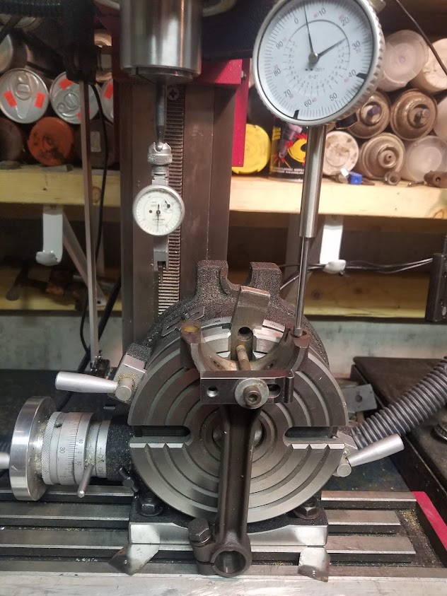
|
Posted By: ac55tractor
Date Posted: 29 Dec 2021 at 5:12pm
|
I
took a fly cutter tool and touched off the top of the flat and removed as
little as possible to take it to clean. So far .003 - .005 is being removed.
 |
Posted By: ac55tractor
Date Posted: 29 Dec 2021 at 5:13pm
|
Posted By: ac55tractor
Date Posted: 29 Dec 2021 at 5:15pm

I measured the 1/2 bore. Then repeat. In the process of cutting the mating surfaces and re-qualify the bearing bore. |
Posted By: ac55tractor
Date Posted: 29 Dec 2021 at 5:16pm
| Please feel free to ask any questions. I will be asking some of my own soon. |
Posted By: ac55tractor
Date Posted: 30 Dec 2021 at 10:16am
|
I felt that I needed to add some clarity to this post. I was installing new -.010 bearings to the connecting rods from my A/C B. For some reason the bearings would not fit the reground crankshaft. I spent a few days trying to figure out how to get them assembled. That's when I turned to the forum. With the advice that I received, it became clear that the bearing bores on the connecting rods somehow became egg shaped in a way that could not be corrected without re-machining them. Adding shim to the parting line would not correct the error. I am a life long Machinist, so reworking the rods is the easy part for me, and I could save a few bucks in the process. In appreciation to the forum, I am taking pictures and sharing my progress with everyone. Steve
|
Posted By: steve(ill)
Date Posted: 30 Dec 2021 at 10:22am
|
Steve, in addition to the rods, please show the rod clamp method, the milling head and boring bar as you do the work........ we would be interested in all parts of the job. ------------- Like them all, but love the "B"s. |
Posted By: ac55tractor
Date Posted: 30 Dec 2021 at 10:44am
|
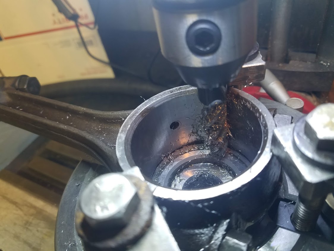
Sure, I will show every thing as I go. I really cannot bore with my mini mill yet. I have to build and install an attachment plate to the back of the machine to make it rigid enough to bore with. In a way it's a flaw in the design of the machine. So for this job, I am going to set the rods up on the rotary table and mill the bore diameters round with a carbide endmill. It will be faster this way and a lot easier to control the diameters as I go. I have a new dial bore gauge coming in today to measure the diameters.
|
Posted By: steve(ill)
Date Posted: 30 Dec 2021 at 12:41pm
|
I am going to set the rods up on the rotary table and mill the bore diameters round with a carbide endmill. well, i dont think i have ever seen that done before, but it should work ! setup will be critical... Your going to do how much ... .005 ?
------------- Like them all, but love the "B"s. |
Posted By: ac55tractor
Date Posted: 30 Dec 2021 at 2:38pm
|
Yes, I am cleaning and squaring up the parting line by .002 - .003 on each cap and rod. When bolted together, prior to milling out the bore, the diameter of the bearing bore will be under-size roughly -.005. The distance across the parting line was already roughly .005 under-size. As I am cutting, I will be removing an almost equal amount all the way around the inside of the bore. The plan is to mill out the bore to 2.059 to 2.060. A 2.059 milled diameter, minus .130 for the thickness of 2 bearings = 1.929. The dimension of the crankshaft connecting rod journal is 1.927. When finished I will have a round bearing bore with .002 clearance for the bearings.
|
Posted By: ac55tractor
Date Posted: 30 Dec 2021 at 4:53pm
|
I just got the dial bore gauge set up. I assembled a rod and cap. The inside diameter landed as planned. It is -.005 top to bottom and -.0045 across the parting line. The bore is practically round. It measures 2.024 diameter. |
Posted By: BrianC
Date Posted: 30 Dec 2021 at 5:19pm
|
Previous post you said you were wanting to machine to 2.059 diameter. Also said after touching off the rod and cap ends, it should be roughly .005 under size. To me that means the diameter should be 2.054. However your last post says it measures 2.024 diameter. Seems like a big difference between your estimate and actual, am I missing something? It seems after skimming the rod and cap ends total of .005 and removing the original .010 shim, it should be .015 under size one direction, just about finished along the split line.
|
Posted By: ac55tractor
Date Posted: 30 Dec 2021 at 5:35pm
|
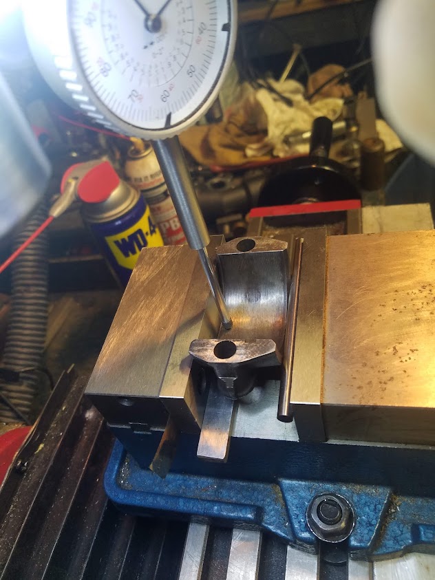
Here is an old Machinist trick that I learned from an old Machinist. See the pin inside the right side jaw (movable jaw) If you have a part and your sides are not exactly parallel, placing a pin in the movable jaw, in the right place will align the part to the vice and the machine. It is critical when machining these parts that the existing bores are parallel to the parting line flats and square or (perpendicular) to the same side on both parts (cap and rod) when assembled. I ran the indicator in and out inside every bore to make sure that they were square to the the solid jaw edge, and the height of the flats on the cap were the same before I cut the parting line flats. I did the same with the rods when they were mounted to the rotary table when I cut them. So now when they are assembled the bore will be square to the same side of the rod and cap. That side will be placed down onto the rotary table.
|
Posted By: ac55tractor
Date Posted: 30 Dec 2021 at 5:46pm
|
The 2.024 was a typo. Should have typed 2.054. Good eye there Brian. I cannot explain anything about any previous shimming. We all know that these rods were shimmed at one time. I am going by what is there now for dimensions, not what was supposed to be there. I am trying to make what I have work. Please keep this in mind, these rods were egged so that the parting lines were small and the rod bore from top to bottom. I don''t have the dimensions in front of me at the moment (laptop is down cellar) but the dimension opposite the parting lines were oversize.
|
Posted By: IBWD MIke
Date Posted: 30 Dec 2021 at 7:12pm
|
I hate to say this but I think your over thinking this. These engines have run for 70+ years with the shims. Yes, it's nice to not have them but they worked with them just fine. On my WD45 rebuild I used rods from a 45, no shims. WD rods have them. I did obsess over the main bearing clearance a bit. Made a lot of shims until I got the clearance where I wanted it.
|
Posted By: ac55tractor
Date Posted: 30 Dec 2021 at 7:22pm
|
I got the laptop, I am looking rod #2 at random . The #2 bearing bore was 2.055 diameter across the parting line, it measured 2.059 diameter top to bottom. These dimensions were taken without shims. If standard bearings were installed and the bore was round, without shims, the 2.059 dimension is within factory spec. 2.059 minus .120 (the thickness for 2 standard bearings) = 1.939 or .002 over the standard journal diameter of 1.937. So from what I can tell the bores top to bottom, were to size already without shim. I noticed this two weeks ago, but I didn't take the time to do the math until just now. The undersize parting line brought me to where I am today reworking the rods. With new bearings installed, The rod would not move on the crank shaft. even with .010 shims. If the bores were ok to begin with, I would be finished with the lower end of the engine by now. This forum page may clear things up. please read through. https://www.allischalmers.com/forum/crankshaft-end-play_topic184466_page2.html" rel="nofollow - https://www.allischalmers.com/forum/crankshaft-end-play_topic184466_page2.html I felt oblagated to show what I was doing because of the help that I recieved from the forum. I have no idea what was done in the past. But these are the dimentions that I recorded as I disassembled. How it ran with an undersized bearing bore dimention on every parting line with an .008 shim on one side is beyond me. I am trying to correct what I have in front of me.
|
Posted By: Les Kerf
Date Posted: 31 Dec 2021 at 6:19am
Standard practice on modern REALLY HIGH performance engines is to squeeze the rod/cap assembly with a c-clamp at the parting line prior to final honing; this results in the bore being as much as 0.007" over-size at the parting line. This is done to compensate for the tendency of the rod cap to flex inward under the extreme stress loading at high rpm. I am puzzled as to how the rods on a presumably stock model B/C engine ever got into the shape that you have measured.  Thank you for posting your excellent photos and detailed description of your project  |
 ac55tractor wrote:
Posted By: ac55tractor
Date Posted: 31 Dec 2021 at 9:36am
|
I can't speak for everyone, I think that most people who have seen this post and my previous post were puzzled by the condition of the rods. (see link above) You would think, if all the engines were manufactured the same, and all shimmed the same, at the factory, the reassembly process should be the same. I am a machinist, not an engine builder. I knew that I had the correct replacement parts and they were not going together. That's when I started measuring the parts, more than once. I documented the dimensions. Things were not adding up and I could not understand what I found, so I presented the results to the forum. I got some real common sense replies to clearly a unique problem. I am making something good out of some distorted parts, and I feel good about it. The main bearing bores are all shimmed. They measure round, and have the correct dimensions. |
Posted By: steve(ill)
Date Posted: 31 Dec 2021 at 9:46am
|
IF you think about it, the rod goes up and down in the engine, changing directions 3200 times per minute... That MAY cause distortion of the rod.. If the rod was to "distort", you would think it would be in the direction of travel... and "possibly" shrink in the cross section thru the clamp area....Your only talking about 2-3 THOUSANDTHS, so it dont take a lot of flex............... this could also happen if the crank was only turned .009 undersize instead of .010 , or if the bearing shells were a couple thousands thicker than assumed.... but i think you have done a good job of discounting those possibilities, so the only think left is that the rod distorted lengthwise under LOAD.. ------------- Like them all, but love the "B"s. |
Posted By: ac55tractor
Date Posted: 31 Dec 2021 at 10:01am
|
Connecting rod distortion was mentioned in all sorts of websites. Sometimes you have to Google the right question. It's clearly not a nitro powered funny car. But apparently the same distortion is possible in a 4 cylinder, low horsepower, low RPM Allis tractor engine. |
Posted By: Les Kerf
Date Posted: 31 Dec 2021 at 10:26am
Yup. Apparently they are weaker than I thought. From your excellent photos and description it appears that someone filed the mating surfaces down by hand, and also did not get things back in place correctly. The shims installed on only one side is odd. I will keep all of this in mind when I get around to overhauling my WD. Edit: The other important point is the fact that this engine ran for 30-some years like this  |
Posted By: ac55tractor
Date Posted: 31 Dec 2021 at 2:45pm
All set up, ready to cut. All of the rod bores are now .005 undersized from the finish diameter. Everything fell into place. 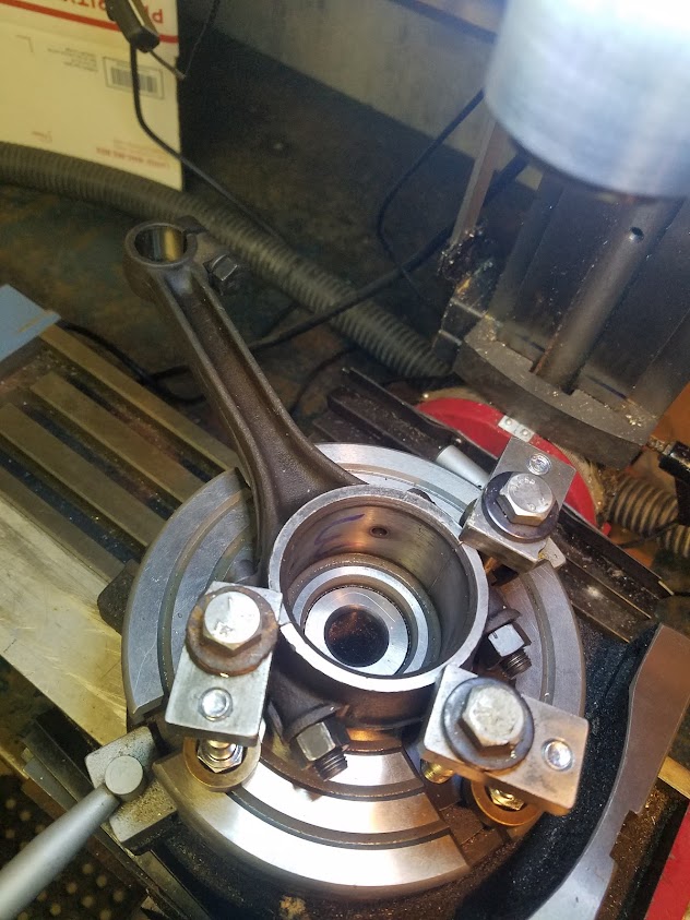 |
Posted By: ac55tractor
Date Posted: 31 Dec 2021 at 5:45pm
|
Posted By: ac55tractor
Date Posted: 31 Dec 2021 at 5:46pm
Diameter is right on the money.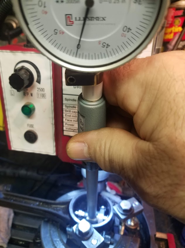 |
Posted By: ac55tractor
Date Posted: 31 Dec 2021 at 5:47pm
I'm very happy with the finish on the bore.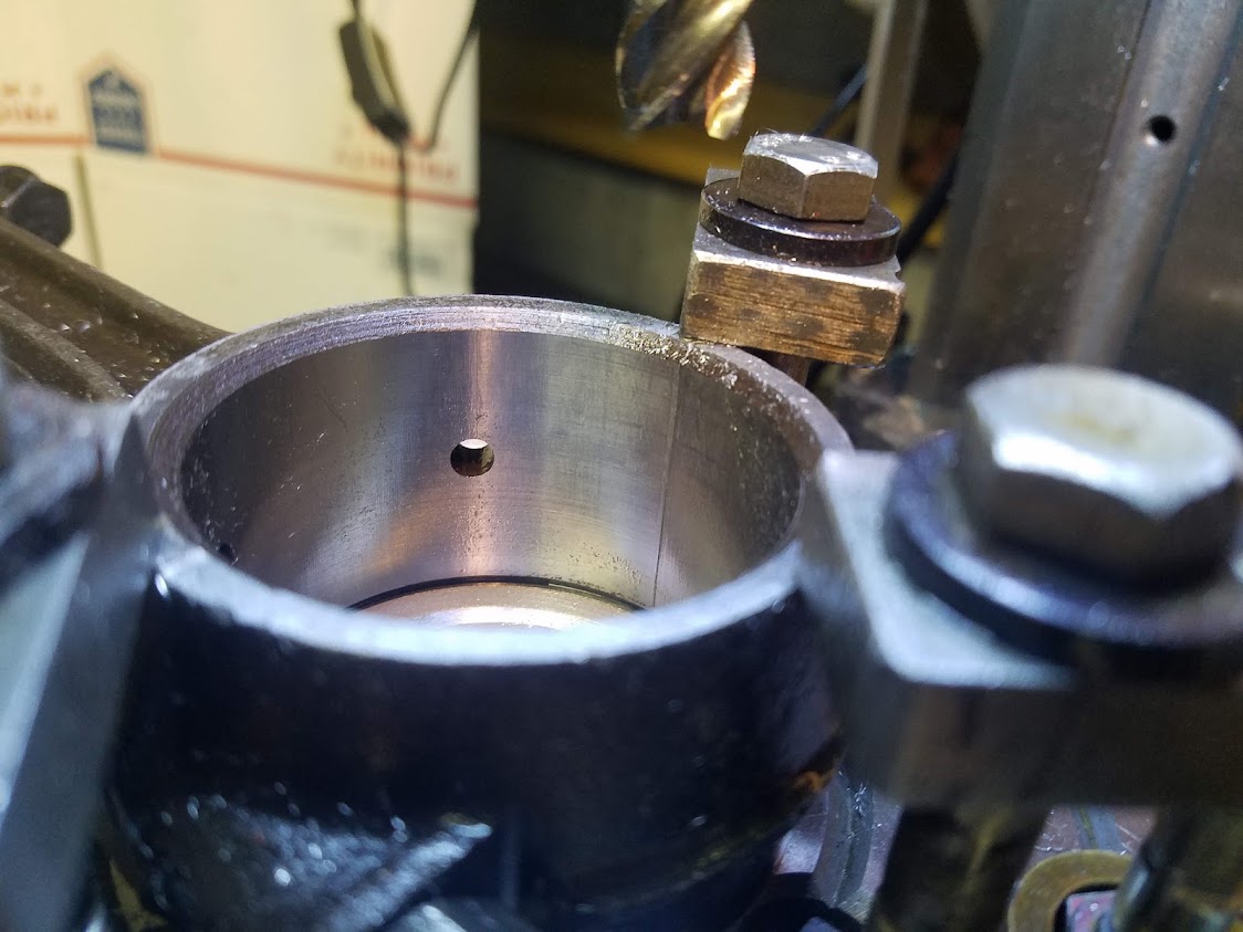 |
Posted By: steve(ill)
Date Posted: 31 Dec 2021 at 6:36pm
looks great..... .0025 cut should be a piece of cake for a good machinist !  
i have never seen a mill used to cut a bore like that.... Will keep it in mind ! ------------- Like them all, but love the "B"s. |
Posted By: ac55tractor
Date Posted: 31 Dec 2021 at 6:42pm
|
Thank you Steve. I don't think that I could have gotten better guidance from anywhere else. |
Posted By: steve(ill)
Date Posted: 31 Dec 2021 at 7:00pm
|
"in theory" you have .002 clearance on the bearings.. Once you TIGHTEN and CRUSH things into place, that might change a thousandth.. If you have to put one thin shim in to get easy rotation, that would not be abnormal..... maybe / maybe not. ------------- Like them all, but love the "B"s. |
Posted By: SteveM C/IL
Date Posted: 31 Dec 2021 at 7:23pm
| While it seems unorthodox, it looks to have worked out well. |
Posted By: MACK
Date Posted: 31 Dec 2021 at 8:29pm
|
If the bore was out of round, how did you center them on the rotary table? No more than it cost at a machine shop with a rod machine, why would you go to that much work. MACK
|
Posted By: ac55tractor
Date Posted: 31 Dec 2021 at 9:22pm
|
By removing .002 or .003 from the parting lines, I turned an egg shaped bore into a round one, before clamping it down to the rotary table. That gave me .005 to remove from the inside of the bore. All of this information is stated above. I used a finger type dial indicator and trued the center of the rotary table to the machine. I eyeballed the connecting rod on to the rotary table and lightly snugged it down to the table with the clamps and used a 12 inch long, 3/8 diameter brass rod to lightly tap it into position while using the finger dial indicator to locate the part to the center of the table. I clamped it down tight, rechecked the part with the indicator and cut it to size. I hope that I was clear. The way I do things, unorthodox, maybe, after over 45 years as a machinist, it was nothing that I was unfamiliar with. Besides I had all of the tools, the machine, and the Yankee Ingenuity to get the job done. All it cost me was the $29.00 for the dial bore gauge from eBay and I didn't have to leave the house. I don't mean any disrespect at all, ever, but what does it cost to have something like that done on a rod machine? Happy new year to everyone. Steve From Maine
|
Posted By: Fred in Pa
Date Posted: 01 Jan 2022 at 8:32am
|
Cut cap ,cut rod , resize bore.Sept. 2021 cost $22.00 pre rod.
------------- He who dies with the most toys is, nonetheless ,still dead. If all else fails ,Read all that is PRINTED. |
Posted By: steve(ill)
Date Posted: 01 Jan 2022 at 8:49am
|
I try to do EVERY job i can at home.. Of course i cant grind a crank. I repair everything i can and make as many new parts as i can.. I dont just do it to save money, i enjoy the challenge.. If i add my time, sometimes i am working for $5. an hour. Sometimes it comes out at $100. an hour. If i CAN do the job, i DO it myself.. Just been that way for over 50 years ....... Probably saved enough money in that time to buy a new truck... all it takes is TIME. ------------- Like them all, but love the "B"s. |
Posted By: Fred in Pa
Date Posted: 01 Jan 2022 at 9:08am
|
Business is Business time is money . if you are doing it your self go for it . ------------- He who dies with the most toys is, nonetheless ,still dead. If all else fails ,Read all that is PRINTED. |
Posted By: ac55tractor
Date Posted: 01 Jan 2022 at 10:44am
|
Thanks Everyone, I appreciate the positive input. Steve from Maine
|
Posted By: SteveM C/IL
Date Posted: 01 Jan 2022 at 10:51am
| Sometimes the smile it puts on your face is worth the work it takes....no mater how practical it is to every one else. I have the "I can fix this" gene too. |
Posted By: tadams(OH)
Date Posted: 01 Jan 2022 at 2:25pm
|
And a lot depend on the tools you have to work with.
|
Posted By: B26240
Date Posted: 01 Jan 2022 at 2:37pm
| You are doing a great job ! one thing I would do is check the chamfer with some bluing on the bearings to make sure they are seated and not hung up on the chamfer. You did not remove enough to cause a problem at .0025 but as mentioned they were probly filed in the past and maybe only one side. Great job!! |
Posted By: ac55tractor
Date Posted: 01 Jan 2022 at 2:50pm
|
Thank you for pointing that out. I have some Dykem Blue. I will check for contact. on the bearings. I will leave the rotary table set up and I can re-cut the chamfer if necessary. Nice to see that someone noticed that while I removed .005 from the diameter, it was only .0025 on a side radially that was removed from the bore. |
Posted By: ac55tractor
Date Posted: 01 Jan 2022 at 5:18pm
The Plastigage shows somewhere between .002
and .003. clearance after hand tightening the nuts with a wrench. After I
removed the mark line left over from the Plastigage, the connecting rod just glides on the
crankshaft. No shims were added. 
|
Posted By: ac55tractor
Date Posted: 01 Jan 2022 at 5:20pm
 There was plenty of clearance at the bearing chamfers. |
Posted By: ac55tractor
Date Posted: 01 Jan 2022 at 5:45pm
|
Oh, after removing the connecting rod from the rotary table, I measured the distance from the center-line of the crank bore to the center-line of the wrist pin and it was 6.497. So I lost .003 to the overall length. We used to say at work, What's a few thousandths between friends. The bearing bore was parallel to the wrist pin within 1/10th of 1 degree. It seems that at the end of the day, all of the prep work, and lining things up, paid off. I am off to donate to the forum. Thanks to everyone for the help. Steve from Maine
|
Posted By: wjohn
Date Posted: 01 Jan 2022 at 8:37pm
|
This was great - thanks for asking questions, and then documenting what you did. It's a good reminder for me to check this as I put my WD engine back together. ------------- 1939 B, 1940 B, 1941 WC, 1951 WD, 1952 CA, 1956 WD-45 |
Posted By: MACK
Date Posted: 01 Jan 2022 at 9:03pm
|
I to do all I Can in house. Just seamed like alot of work for the cost done on a rod machine. Have built alot of pulling tractor parts. Overdrive gear boxes, aluminum cylinder heads, and ect. Still make steel fire rings for head gaskets. Thanks for your post, it was interesting. MACK
|
Posted By: ac55tractor
Date Posted: 01 Jan 2022 at 11:01pm
|
Thanks, it was fun to show and tell. It's was really not a lot of work to setup and run these parts. I had the time, tools and the machine. Most of my time was spent taking measurements, and
decide whether to scrap them out, or rework the ones I have, and fix them myself. Once
I found that they were straight, I started chatting with the forum to try to
figure out what need to be done to correct the egg shaped bores. https://www.allischalmers.com/forum/crankshaft-end-play_topic184466.html?KW= I got a message from Lon(MN) He said "I send the rods out to be resized without shims. I also get them aligned. All the rods I have sent out were egg shaped" I sort of read between the lines in what he was saying, and decided to fix them myself. After that, Steve(ill) said to me, as I understood it, "Most do not
send them out due to time and cost... , Being a machinist and "you need
the practice"  .. eliminating the shims and boring the rods to size is an excellent idea !" .. eliminating the shims and boring the rods to size is an excellent idea !"I know that there are people out there with skills that I don't have. I am no better than anyone else. Nor, do I try to be. Being a machinist, sure I get a bit anal about stuff. But you know, I guess that being that way can sometimes work in my favor. I tend to find a direction to go in, and follow the path. At times, it takes some forethought. "thinking two or three steps ahead" But with that mindset, in the end, things do tend to fall into the right place for me. Sure there are times that I have failed, that's why they make welding machines and Welders to run them. As an example, If I make one edge flat. I can be confident that I can rely on that edge to get the next step to fall into place. It usually does. Joking here >If I was a hack the final result would be a pile of #$@%. I hear that these engines are designed to be repaired in the field. That may be true, but my goal is, if I get this done right, and into tolerance, I won't have to pull it apart 30 minutes after I fire it up for the first time. It looks like I got a bit long winded here. Pushing midnight Good night. Steve from Maine
|
Posted By: BrianC
Date Posted: 02 Jan 2022 at 8:30am
|
Were the ends of the bearing shells too long, did you have to fit them?
|
Posted By: ac55tractor
Date Posted: 02 Jan 2022 at 1:25pm
|
Yes, I hand fit them, I have to up front here. The method that I used here will not work for everyone. If you are more comfortable with a hand file, than by all means, file them in to height. After machining the parting lines on the caps and rods, I knew that I could count on the bearings to be flat and parallel to the bores in the rods. I flat lapped the ends of the bearings into place using a full-size sheet
of 240 emery cloth, laid down flat on my large drill press table. I shot
the emery cloth with WD-40 as a lubricant. < lubricant is very important. Looking at the cap in front of you, the bolt holes should be front to back, and not to the left and right as you lap them in. I placed a bearing in the cap, and or
the rod, placed my thumb and fore finger on the cap holes, applied even pressure and started rubbing (lapping) the cap and bearing back and forth and in a figure "8" pattern. This brought the bearing into height inside the cap. The material that the bearing is made of is considerably softer than
the cap, and rod. If you press lightly as you go, and keep the emery cloth wet, nothing will get damaged. Do not force them. Once I felt it reach the flats on the cap, I stopped, and looked close at the part. If it looks like you have reached the parting line, remove the bearing. Wipe everything off clean and break the lapped sharp edges on the bearing flats with a file, wipe them off clean again, and reinstall into the cap. Yes I know, I have zero "crush" on the bearings, when they were assembled. My cap faces are flat, and true to the bearing bores. When assembled, the bearing ends and the caps make 100% contact to each other, the bearing ends are not crooked and didn't go under size in the process. If you use shims, stop lapping before reaching the parting line, and measure how far the bearing extends out of the cap. That will give you the room for shimming and crush. That is an option that will work for you. It worked for me two or three weeks ago when I was experimenting with shims and crush in the caps. I have lapped parts more than once with emery
cloth and WD-40 on all sorts of jobs at work. In the
end you will get a surface as flat as the surface under the emery cloth. Choose your flat surface wisely. You can also use a full size table saw table to lap parts with. Steve from Maine
|
Posted By: ac55tractor
Date Posted: 02 Jan 2022 at 10:18pm
|
I think that I was over confident about the zero crush fit. I can skim cut the cap and get the.0015 crush.
|
Posted By: steve(ill)
Date Posted: 02 Jan 2022 at 11:15pm
|
Im not sure thats a necessity... You might be better off to leave it as is. ?? You have your .002 bearing clearance to shaft, and there is no way the bearing is going to move or get out. ------------- Like them all, but love the "B"s. |
Posted By: SteveM C/IL
Date Posted: 02 Jan 2022 at 11:26pm
| I would bet that without some crush,the bearing will loosen in it's bore. All inserts I am aware of use a certain amount of crush to keep things tight. |
Posted By: ac55tractor
Date Posted: 03 Jan 2022 at 10:22am
|
After some internet searching last night, I read this statement. When applied to the technologies of shell bearings, it is not a good idea to 'crush'; it is absolutely necessary. Will this solution work? I have only fit one set of bearings so far. It's the #3 connecting rod. All of the other bearing shells are new and unaltered. I went through the other bearing cap dimensions. They all vary within .003 based on how much I had to remove when I took the parting lines to clean. The #1 cap is .002 shorter than #3 cap from the parting line to the bottom of the bore radius. I can swap out the bearing shell from #3 cap into the #1 cap, then place a new half shell into the #3 cap. When I finish, after a slight lapping, the #1 cap will have a bearing crush height of .0015, and the #3 cap with the new bearing, can be lapped into .0015 crush height.
|
Posted By: steve(ill)
Date Posted: 03 Jan 2022 at 11:56am
|
sounds like a good plan !. I was just worried if you machine the rod face, you loose the .002 bearing to shaft clearance and then you starting over. ------------- Like them all, but love the "B"s. |
Posted By: ac55tractor
Date Posted: 03 Jan 2022 at 1:04pm
|
Thanks for confirming that Steve There is so much to know, and to understand with the engine work when looking at it through machinist eyes. I think that I may now have a grasp on shimming. At first, It just didn't make any sense to me. |
Posted By: steve(ill)
Date Posted: 03 Jan 2022 at 1:15pm
|
IF you had already cut all the bearing, is would have taken one half and tapped on the last 1/16 inch with a ball peen hammer to distort the edge out .001 to get some CRUSH ( dont looked shocked.. dont take much to get .001 distortion)... but since you still have the other bearings to mix and match, that is a good idea. ------------- Like them all, but love the "B"s. |
Posted By: ac55tractor
Date Posted: 03 Jan 2022 at 1:51pm
|
How did you know that I looked shocked? Is my camera on? I got to get back to it. I goofed off way too much this weekend. I have to finish fitting the rod bearings. For now, let me throw this question out. With out damaging anything, what is the best way to torque the connecting rod to the wrist pin? The torque required for the rod to the wrist pin is not listed in my Allis Chalmers service manual. It only says "Clamped in rod" I know one thing, it took a lot of "reefing" to get the bolt loose on the connecting rod. Very grateful for all the help. Steve |
Posted By: steve(ill)
Date Posted: 03 Jan 2022 at 2:11pm
|
when no torque is listed, you normally use grade 5 specs, unless you are SURE it is a grad 8 bolt... Read the book TWICE on installing the piston and rod assemblies in the engine.. There is a FRONT and BACK to the rods... they are offset. ------------- Like them all, but love the "B"s. |
Posted By: ac55tractor
Date Posted: 03 Jan 2022 at 2:16pm
|
Okay thanks. I understand Grade 5 and Grade 8 specs. Thanks again Steve
|
Posted By: MACK
Date Posted: 03 Jan 2022 at 8:39pm
| Put a good pin in vice that will go through wrist pin (3/8 extenson). Put pin through wrist pin and torque. MACK |
Posted By: ac55tractor
Date Posted: 03 Jan 2022 at 9:01pm
|
Oh, okay, I get it. Thanks Mack. I realized earlier that even though the connecting rod is off center, the piston is not. So I should be able to center the pin inside the piston and tighten it down. Mack, I was wondering If I would hear back from you. I had never heard of a fire ring, so I looked it up. That is a great idea for creating a seal in a cylinder head. My family and I go to the Cumberland Fair here in Maine every September. I have been known to sneak off with my grandson to watch the tractor pulls. It's amazing, the horse power that those tractors can create. Thanks again for the idea. Steve
|
Posted By: Lonn
Date Posted: 05 Jan 2022 at 5:28pm
|
One important reason for bearing crush is heat dissipation. The bearing could burn out without the bearing crush because the back of the bearing surface needs to be in tight contact with the rod and cap to take away the heat.
------------- -- --- .... .- -- -- .- -.. / .-- .- ... / .- / -- ..- .-. -.. . .-. .. -. --. / -.-. .... .. .-.. -.. / .-. .- .--. .. ... - Wink I am a Russian Bot |
Posted By: ac55tractor
Date Posted: 05 Jan 2022 at 7:02pm
|
Thank you for that. It only adds to the fact that bearing crush is absolutely necessary. I have a question.
Does the bearing have to extend out of both the cap and the rod, or will it work with having the extension come out of the cap only? Thanks Steve |
Posted By: SteveM C/IL
Date Posted: 06 Jan 2022 at 1:58pm
| I don't think it matters....have messed with some rebuild rods an know the shell stuck out a little but can't tell you whether rod or cap.My belief is as long as you have crush you're ok. I am no authority..... |
Posted By: JK in Pa
Date Posted: 06 Jan 2022 at 2:05pm
| The wrist pins cannot be centered. Directions will get you there. Many rebuilds were ruined in a mater of hours. |
Posted By: steve(ill)
Date Posted: 06 Jan 2022 at 3:28pm
|
John, on the smaller B/ C motor , i think the pin is centered in the piston... Its the CRANK end of the rod you have to watch how you install........ Now the WC / WD motor I believe is not centered on the piston end ??? ......... and all the rods go in the same way on the CRANK end ?? ------------- Like them all, but love the "B"s. |
Posted By: JK in Pa
Date Posted: 06 Jan 2022 at 3:42pm
| Steve, you are right. I was thinking he was working on a WD Motor. Sorry for the confusion. |
Posted By: ac55tractor
Date Posted: 06 Jan 2022 at 3:46pm
|
Thank you SteveM C/L, Thank you JK in PA. and Thank you Steve (ill) I am going over the service manual right now. The pins are centered. No problem, I know that I have the best guidance on this overhaul. |
Posted By: steve(ill)
Date Posted: 06 Jan 2022 at 3:55pm
|
just watch the CRANK END of the rod... they dont all go in the same way. ------------- Like them all, but love the "B"s. |
Posted By: ac55tractor
Date Posted: 06 Jan 2022 at 4:15pm
|
Joke here I can always use the ball pean to get them to fit. Truth here. But Steve, they all came out aiming the same direction. You know that I will be sure that they get reinstalled properly. Something tells me that there was side play inside the piston at the wrist pin to allow the incorrect offset. That may explain the broken piston ring. Not sure, who knows? I have a whole list of questions. I Just want to get through fitting these rods first. Here is one for you all. The floating oil pickup is attached to the pipe that goes to the block. The pickup is attached with one tube going into another and held in with a cotter pin. Is it possible, that along with the oil that is being pulled up, if air being pulled up as well.
|
Posted By: steve(ill)
Date Posted: 06 Jan 2022 at 4:51pm
|
the screen should be well BELOW the oil line.. should not suck air. ------------- Like them all, but love the "B"s. |
Posted By: ac55tractor
Date Posted: 06 Jan 2022 at 6:47pm
|
It was something that I noticed, I was curious about it. Thanks. |
Posted By: ac55tractor
Date Posted: 11 Jan 2022 at 3:49pm
|
Over last weekend, I was able to get in contact with the son of the original owner of my Allis B. I asked him if he knew anything about the engine being worked on in the past. He said that he remembered that his father was getting lower end noise from the engine. He said his father worked on the crankshaft. He pulled shims out, and ground the flats of the connecting rods to get the connecting rods to fit. He remembered that they squeezed the rods in a vice at the parting lines because he removed too much from the flats on the rods to get them to fit.
That explained to me how the bores on the connecting rods became egged. I finished the rods today. I am very happy with they way that they spin freely on the crankshaft.  |
Posted By: BrianC
Date Posted: 11 Jan 2022 at 5:22pm
|
Does it make sense to balance the rods? Pistons? I lost track of what all you are doing. Maybe you can recap the scope of the rebuild? I know you worked on the main journal bearings and end play. New pistons, rings and liners? Rings- end gap and clearance/fit to grooves in pistons. Liners- protrusion and o-ring sealing. If the block's sealing surface is corroded they might leak. The camshaft, you should put the lifters back to the lobe where they came from.From my experience the top problems of rebuilds are crank/rod bearing issues, wet liner leak, head gasket leak. Another is the darn rear main seal leaking. Interesting to me, I have a '48 C needing an engine rebuild. |
Posted By: steve(ill)
Date Posted: 11 Jan 2022 at 6:28pm
|
He remembered that they squeezed the rods in a vice at the parting lines because he removed too much from the flats on the rods to get them to fit. well........... i dont remember reading that one in the service manual !! ------------- Like them all, but love the "B"s. |
Posted By: ac55tractor
Date Posted: 11 Jan 2022 at 6:32pm
|
I have a new
set of pistons, rings, and liners. I checked the block closely and it seems to be in great shape. I
checked the top of the bare block with a straight edge. There was no deviation
or uneven areas. I spent a lot of time cleaning the oil sludge out of the block
and getting the dirt out of the coolant chamber. I purchased
an oil pump rebuild kit and have lapped the back plate flat. That Is ready to
go. I rebuilt
the governor assembly. At first the
liners would not go all the way down into the block. I lightly honed the lower
liner diameter with a small wheel cylinder hone and some light oil, and the
liners slide right in now, without the “O” rings attached. After
setting the liners into place, (without “O” rings), I checked the protrusion
for the liners. They sit cleanly in the block with a .002 - .004 protrusion. The camshaft
lifters were pulled, cleaned, numbered, tagged, and bagged. I have installed
new cam bearings, and I purchased a remanufactured cam shaft. After
measuring the cam all the cam lobes are the same height, and the 3 bearing
journals each measure 1.749. After getting
the cylinder head milled flat. I have rebuilt the cylinder head with new
valves, springs, and valve guides. Lapped the valves to the new valve seats. That’s all I
can think of right now. I haven’t gotten to setting the gap on the rings yet. I
was wondering if it was necessary for me to make a ring squaring tool to
seat the piston ring squarely in the bore, to use a feeler gauge to check its
gap. I have a
better idea how to maintain bearing crush and how shimming the split line
works. I have never heard of ether of these. I am not an
engine rebuilder. I feel that I do have enough common sense to assemble this
engine into spec. Having the service manual and a parts number book has been a
big help as well. |
Posted By: steve(ill)
Date Posted: 11 Jan 2022 at 6:40pm
sounds like you are building a RACE CAR !!!............... 125 cubic inch / 20 HP..  ------------- Like them all, but love the "B"s. |
Posted By: ac55tractor
Date Posted: 11 Jan 2022 at 6:40pm
|
I had to get an answer on those rods. I contacted the guy who sold me the tractor. (He was the builder of my house and my former neighbor.) He was easy to find. He said that he traded an old station wagon for the tractor in the late 80's. Unfortunately the original owner had passed away over 10 years ago, but he was able to get in touch with his son for me. We spoke on the phone for almost an hour. He seemed happy to hear that Wendy and I were taking good care of his fathers Allis B.
|
Posted By: ac55tractor
Date Posted: 11 Jan 2022 at 6:47pm
| Oh, I forgot to mention that I took the plunge, and got oversize pistons, rings, and sleeves. Got to have that extra 1 or 2 horsepower when I really need it. |
Posted By: MACK
Date Posted: 11 Jan 2022 at 8:06pm
| Use your pistons to square the rings. MACK |
Posted By: ac55tractor
Date Posted: 11 Jan 2022 at 8:32pm
|
Thanks Mack That's a good Idea. That will save me some time. |
Posted By: ac55tractor
Date Posted: 11 Jan 2022 at 8:44pm
|
Just after Christmas, I tried to place a ring into the (bottom) of one of the sleeves. As it went in, it made a short scratch in the liner. I looked at the gap, it looked at the gap by eye, close to .010, maybe less. I pulled the ring out and put it back in the package. Before I place another ring in a sleeve, I am going to check it for burrs, Clearly, I have a lot of work ahead of me. The engine is in the cellar. I work on it for a few hours every day. Some days I don't go near it at all. |
Posted By: wjohn
Date Posted: 12 Jan 2022 at 11:00pm
Are you going to resurface the lifters since the reman camshaft had the lobes ground (I presume)? The guidance I got and info I found around the internet suggested this was a good idea when installing a reground cam. Here's a thread I started where I asked the question and ended up resurfacing my WD lifters myself once I discovered that a brand new lifter for that engine was flat. I do not know for certain if the B engine lifters were flat or slightly convex when new. Another potential risk is that I do not know if they are hardened to a certain depth that I might have gotten into. Other members had done this before so I thought it was low risk. I still have not gotten my engine back together yet unfortunately. Just wanted to bring this up if you hadn't thought about it yet. https://www.allischalmers.com/forum/matching-used-camshaft-and-lifters_topic172539.html" rel="nofollow - https://www.allischalmers.com/forum/matching-used-camshaft-and-lifters_topic172539.html ------------- 1939 B, 1940 B, 1941 WC, 1951 WD, 1952 CA, 1956 WD-45 |
Posted By: ac55tractor
Date Posted: 13 Jan 2022 at 8:04pm
|
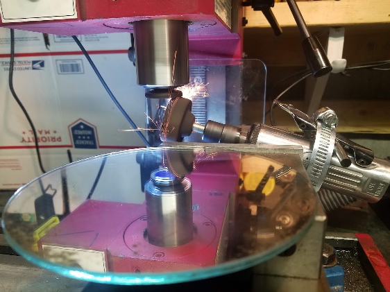
wjohn, I want to thank you for sending out that link to me. I read it over and the last thing that I need is chunks of chipped up lifters in the oil pan. I checked a couple of lifters and they were flat on the bottom. Then I picked up a third one. It was #5. It was concave. That was the lobe number that was warn out on the cam that I pulled. I am going to fix the lifters here at the house. Thanks again for the heads up. Steve (inME)
|
Posted By: ac55tractor
Date Posted: 15 Jan 2022 at 1:34pm
|
Posted By: ac55tractor
Date Posted: 15 Jan 2022 at 1:35pm

|
Posted By: ac55tractor
Date Posted: 15 Jan 2022 at 1:36pm

|
Posted By: ac55tractor
Date Posted: 15 Jan 2022 at 1:37pm

|
Posted By: BrianC
Date Posted: 15 Jan 2022 at 4:04pm
|
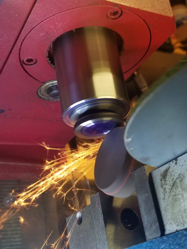
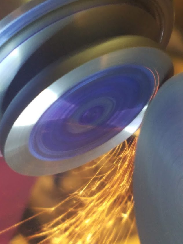
That looks nice. In the last picture it looks finer, I guess you lapped it. The camshaft makers are fanatically adamant about the proper assembly lube and break-in oil, and priming the oil system for first start up. That is for high revving latter day engines. Yours is 1600 rpm, low spring pressure. Still, I would get some of that camshaft assembly lube. |
Posted By: ac55tractor
Date Posted: 15 Jan 2022 at 4:31pm
|
Thanks Brian I am lapping the lifters on a sheet of 220 grit, then to 400 grit, with penetrating oil against a flat plate. I plan on using Permatex Ultra Slick Engine Assembly Lube. I have been wondering about what to use for break in oil in the crank case at start up. Any suggestions, would be appreciated. Thanks again Steve (inME.)
|
Posted By: ac55tractor
Date Posted: 18 Jan 2022 at 6:49pm
|
Posted By: ac55tractor
Date Posted: 18 Jan 2022 at 6:49pm
|
Posted By: ac55tractor
Date Posted: 18 Jan 2022 at 6:50pm
|
Posted By: ac55tractor
Date Posted: 18 Jan 2022 at 6:55pm
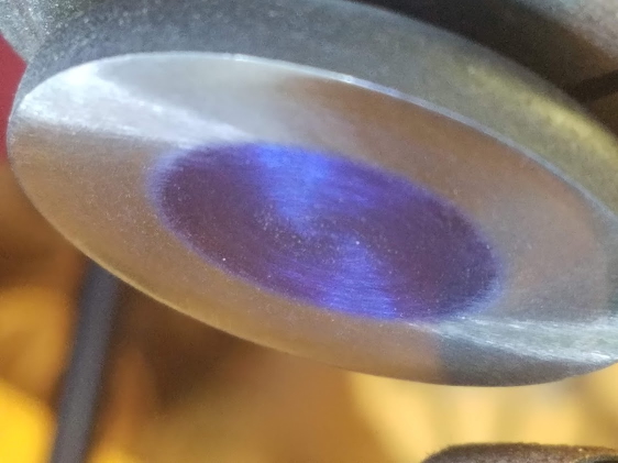
 8 more horsepower Steve? I don't think so. I did have to remove almost 1/32 to get this one to clean. Some of the others weren't so bad.
|
Posted By: BrianC
Date Posted: 18 Jan 2022 at 8:19pm
|
I used to have a tool post grinder for my lathe. Someone walked away with it. Step by step, keep it up.
|
Posted By: SteveM C/IL
Date Posted: 18 Jan 2022 at 9:33pm
| If they were hard faced to begin with,that is long gone on that one so even a soft face in good shape should be better on the cam. |
Posted By: ac55tractor
Date Posted: 18 Jan 2022 at 10:26pm
|
Thanks Brian, Man that's too bad. A tool post grinder can be really handy with machining hardened parts on a lathe. I used to work in an electric motor repair shop. BIG electric motors for the paper mills.  |
Posted By: ac55tractor
Date Posted: 18 Jan 2022 at 10:26pm
|
That is a good point Steve. I would like to think that they are hardened throughout. If
it is hard faced, you are right, it wouldn't be like the others. I
watched for the spark to change color, it stayed the same. I know that
doesn't mean much, but what is there should still hard. How deep the hardness goes in these parts? That's beyond me. I appreciate the input. Steve
|
Posted By: ac55tractor
Date Posted: 18 Jan 2022 at 11:02pm
|
For a little bit of clarity. For those who might not know, that is a tool post grinder that I am standing next to. Steve (inME)
|