| Author |
 Topic Search Topic Search  Topic Options Topic Options
|
C in Concord 
Bronze Level


Joined: 26 Sep 2019
Location: Concord, WI
Points: 109
|
 Post Options Post Options
 Thanks(0) Thanks(0)
 Quote Quote  Reply Reply
 Posted: 14 Feb 2020 at 9:35pm Posted: 14 Feb 2020 at 9:35pm |
I agree on the 1-wire mini (denso) alternator for ~$40. I put one on my C as part of a 12v conversion and it's been working well for going on a year now. Fits nice too, fully covered by the hood. Only used the post, ignored the other terminals. Pulley is ~3", maybe a 1/4" smaller than the generator pulley. Plowed the driveway at 3 deg. F yesterday. 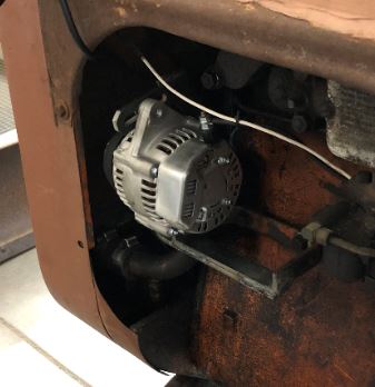
|
|
Leave things better than you found them.
1941 Model C (restored 2020)
|
 |
|
Sponsored Links
|
|
 |
Steve in NJ 
Orange Level Access


Joined: 12 Sep 2009
Location: Andover, NJ
Points: 11887
|
 Post Options Post Options
 Thanks(1) Thanks(1)
 Quote Quote  Reply Reply
 Posted: 14 Feb 2020 at 11:42pm Posted: 14 Feb 2020 at 11:42pm |
All what wiring?? There's two more wires to hook up on a three wire system. I'm not condemning one wire systems. I explained this numerous times in the past here. If you own a B or C Tractor that's equipped with a Mag and a Starter, then the one wire will work fine. When you have a Tractor with more accessories like, Battery ignition (Distributor) Headllights, work lamps, etc. the one wire ain't gonna cut it. Without the VR being wired into the system, the Alternator is just going to charge the Battery at a certain amperage. Let me explain. When you have other accessories pulling on the Battery, the Battery eventually starts to run down because it can't keep enough power in it to keep the accessories happy and stay fully charged at the same time. Here's where the problems start with the one wires. Enter the three wire. With the Voltage Regulator now wired into the system and monitering current usage, when other accessories are being used, the VR senses current usage and ramps the Alternator up to compensate for that usage. This way, everything on board the Tractor is getting full voltage and the Battery is staying full also. This is where the 3 wire system has the advantage. The more accessories (or current) that is used while the Tractor is working, the Alternator satisfies the system (especially the Battery) in keeping everything working at peak voltage. That same Denso used as a one wire on a "D" series Tractor can be a real work out for that Alternator. The higher "D" series Tractors have a lot going on at the dash with gauges, work lamps etc. and is using a lot of current from just the Battery. Now, during the day, if a lot of those accessories like Headlights, tailights, flashers, etc aren't being used, the Alternator can usually keep the Battery reserve up. Some of you guys may not have a problem and say "it works fine for me". But, take a senario where you get a Winter storm and you're working to clear the driveway and around the barns at night and you need all the lights and crap working, you're gonna have a problem cause the Battery having all those parisites suckin' on it is eventually going to go down, so now your loosing current flow to the ignition, your lamps, gauges and anything else you need current for. The engine is going to go down on power, and Heaven forbid you have Statium lights and a heater or A/C in the cab! With the three wire system, the VR is doing its job compensting for all those draws on the system, and the Alternator can stay with all those draws and keep the Battery reserve at peak. When I design one my systems for a large "D" series Tractor, or larger, I always send the voltage sense wire (part of the 3 wire system) up parallel with the heavy output circuit and junction the two together at the Voltmeter plus (+) side in the dash where its busy. This allows the VR to monitor current usage at one of the busiest points on the Tractor and keeps everything up to peak. Trust me, I've been building and designing wiring systems on race cars, streetrods, all kinds of vehicles including Tractors for darn near 50 years. What you want is SAFETY and RELIABILITY under all conditions. HTH Steve@B&B
|
|
39'RC, 43'WC, 48'B, 49'G, 50'WF, 65 Big 10, 67'B-110, 75'716H, 2-620's, & a Motorhead wife
|
 |
JW in MO 
Orange Level


Joined: 16 Feb 2010
Location: South KC Area
Points: 2627
|
 Post Options Post Options
 Thanks(0) Thanks(0)
 Quote Quote  Reply Reply
 Posted: 15 Feb 2020 at 8:16am Posted: 15 Feb 2020 at 8:16am |
 Steve in NJ wrote: Steve in NJ wrote:
All what wiring?? There's two more wires to hook up on a three wire system. I'm not condemning one wire systems. I explained this numerous times in the past here. If you own a B or C Tractor that's equipped with a Mag and a Starter, then the one wire will work fine. When you have a Tractor with more accessories like, Battery ignition (Distributor) Headllights, work lamps, etc. the one wire ain't gonna cut it. Without the VR being wired into the system, the Alternator is just going to charge the Battery at a certain amperage. Let me explain. When you have other accessories pulling on the Battery, the Battery eventually starts to run down because it can't keep enough power in it to keep the accessories happy and stay fully charged at the same time. Here's where the problems start with the one wires. Enter the three wire. With the Voltage Regulator now wired into the system and monitering current usage, when other accessories are being used, the VR senses current usage and ramps the Alternator up to compensate for that usage. This way, everything on board the Tractor is getting full voltage and the Battery is staying full also. This is where the 3 wire system has the advantage. The more accessories (or current) that is used while the Tractor is working, the Alternator satisfies the system (especially the Battery) in keeping everything working at peak voltage. That same Denso used as a one wire on a "D" series Tractor can be a real work out for that Alternator. The higher "D" series Tractors have a lot going on at the dash with gauges, work lamps etc. and is using a lot of current from just the Battery. Now, during the day, if a lot of those accessories like Headlights, tailights, flashers, etc aren't being used, the Alternator can usually keep the Battery reserve up. Some of you guys may not have a problem and say "it works fine for me". But, take a senario where you get a Winter storm and you're working to clear the driveway and around the barns at night and you need all the lights and crap working, you're gonna have a problem cause the Battery having all those parisites suckin' on it is eventually going to go down, so now your loosing current flow to the ignition, your lamps, gauges and anything else you need current for. The engine is going to go down on power, and Heaven forbid you have Statium lights and a heater or A/C in the cab! With the three wire system, the VR is doing its job compensting for all those draws on the system, and the Alternator can stay with all those draws and keep the Battery reserve at peak. When I design one my systems for a large "D" series Tractor, or larger, I always send the voltage sense wire (part of the 3 wire system) up parallel with the heavy output circuit and junction the two together at the Voltmeter plus (+) side in the dash where its busy. This allows the VR to monitor current usage at one of the busiest points on the Tractor and keeps everything up to peak. Trust me, I've been building and designing wiring systems on race cars, streetrods, all kinds of vehicles including Tractors for darn near 50 years. What you want is SAFETY and RELIABILITY under all conditions. HTH Steve@B&B
|
That right there is valuable and FREE informaion. Thank you for explaining it.
|
|
Maximum use of available resources!
|
 |
Sugarmaker 
Orange Level


Joined: 12 Jul 2013
Location: Albion PA
Points: 8328
|
 Post Options Post Options
 Thanks(0) Thanks(0)
 Quote Quote  Reply Reply
 Posted: 15 Feb 2020 at 3:59pm Posted: 15 Feb 2020 at 3:59pm |
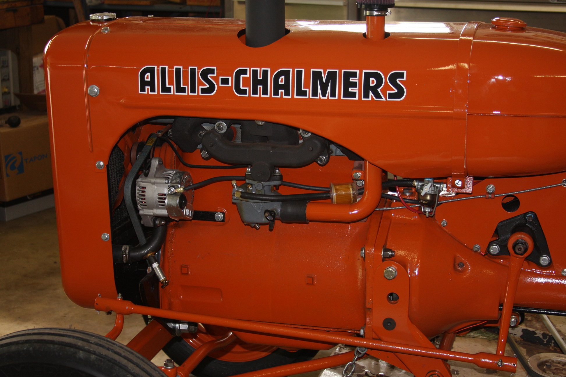
Folks, I like Steves write up. On my WZ which only has battery and lights for ocasional use I used the Denso 1 wire. On my WD45 I used the larger alternator 3 wire. I have followed Steve's lead and have had no issues. The WZ one wire:
The WD45 three wire:
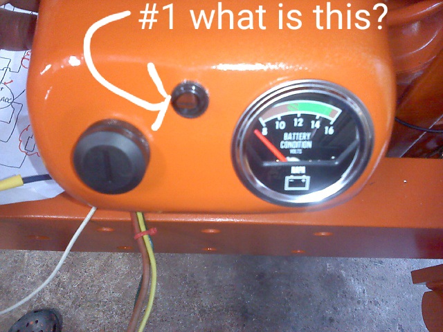
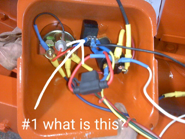
Dash that I typically set up, not factory:
I have a wiring diagram I use if needed I can post that too. Just trying to help. This is custom wiring. Not extremely difficult but, its not the way they came from the Allis plant!:) This is my version/ sketch of the WD series wiring with a 3 wire alternator. Regards, Chris
|
|
D17 1958 (NFE), WD45 1954 (NFE), WD 1952 (NFE), WD 1950 (WFE), Allis F-40 forklift, Allis CA, Allis D14, Ford Jubilee, Many IH Cub Cadets, 32 Ford Dump, 65 Comet.
|
 |
wbecker 
Orange Level

Joined: 29 Oct 2009
Location: STL
Points: 837
|
 Post Options Post Options
 Thanks(0) Thanks(0)
 Quote Quote  Reply Reply
 Posted: 15 Feb 2020 at 5:28pm Posted: 15 Feb 2020 at 5:28pm |
I bought a mini 1 wire from a automotive hot rod site. Works great, charges instantly at low rpm.
|
|
Allis B, IB, Low B, G, D10, JD M, 8KCAB, C152
|
 |
AaronSEIA 
Orange Level

Joined: 11 Sep 2009
Location: Mt Pleasant, IA
Points: 2557
|
 Post Options Post Options
 Thanks(0) Thanks(0)
 Quote Quote  Reply Reply
 Posted: 15 Feb 2020 at 6:36pm Posted: 15 Feb 2020 at 6:36pm |
Hey, Chris...I love the diagram. Helps a bunch. I see you threw a diode in there. I've also seen a small incandescent light or a resistor used where you have the diode. Does it matter which one gets used? AaronSEIA
|
 |
steve(ill) 
Orange Level Access


Joined: 11 Sep 2009
Location: illinois
Points: 82529
|
 Post Options Post Options
 Thanks(0) Thanks(0)
 Quote Quote  Reply Reply
 Posted: 15 Feb 2020 at 7:20pm Posted: 15 Feb 2020 at 7:20pm |
|
i use a 10 ohm, 10 watt resistor with a SI10 alternator and a 10 ohm, 100 watt resistor with the CS130 ( smaller GM) in place of the diode... Basically the same result.. Resistor is 1/4 inch square and about 1.5 inch long .... I normally anchor a terminal block under the gas tank and screw the resistor leads down instead of making spade terminals on them
|
|
Like them all, but love the "B"s.
|
 |
Gerald J. 
Orange Level

Joined: 12 Sep 2009
Location: Hamilton Co, IA
Points: 5636
|
 Post Options Post Options
 Thanks(0) Thanks(0)
 Quote Quote  Reply Reply
 Posted: 15 Feb 2020 at 8:13pm Posted: 15 Feb 2020 at 8:13pm |
|
The purpose of the resistor, lamp, or diode in the three wire alternator connection on the exciting wire is important. That circuit is usually supplied by the gas engine ignition circuit / switch. Without the diode, lamp, or resistor turning the ignition switch off takes away battery power but the alternator will back feed enough power through that wire to supply ignition for the engine so it won't stop from turning the key off. The diode, resistor, or lamp cuts the power to the ignition circuit enough the engine will quit running with the alternator connected that way and the key turned off.
Gerald J.
|
 |
Gerald J. 
Orange Level

Joined: 12 Sep 2009
Location: Hamilton Co, IA
Points: 5636
|
 Post Options Post Options
 Thanks(0) Thanks(0)
 Quote Quote  Reply Reply
 Posted: 15 Feb 2020 at 8:25pm Posted: 15 Feb 2020 at 8:25pm |
|
I know Steve prefers the voltmeter. It sure is a lot easier to wire, but in my experience fails to give thorough charging system indication. When the voltmeter is connected somewhere in the battery circuits in the tractor it indicates a voltage higher than the voltage at the battery because of voltage drop in the multi amps charging circuit. And it indicates that the battery would be being charged IF the battery is connected. Remember that the battery posts need to be cleaned twice a year in a 6 volt system because they tend to corrode and the 6 volt system can't overcome the resistance of the corrosion. They need cleaning every other year in a 12 volt system.
I had a VW Beetle in the late 60s that had a lab quality voltmeter and an ammeter that I had added. The ammeter showed lack of battery charging at low engine speeds while the voltmeter showed adequate voltage.
I prefer the ammeter and it has to be wired properly. For negative ground, the negative terminal should be connected directly to the battery with a wire big enough to carry the full current from the alternator or generator. Then the charging device should be connected to the positive terminal along with all the electric loads of the system.
It would work to connect the voltmeter directly to the battery except that when the tractor was parked the voltmeter would drain the battery in time. And would still not show the effects of corroded posts.
I am a retired consulting electrical engineer with lots of education, Dr. Gerald J. And I have modified the charging on my JD gas 4020 decades ago. I added an ammeter.
Gerald J.
|
 |
Sugarmaker 
Orange Level


Joined: 12 Jul 2013
Location: Albion PA
Points: 8328
|
 Post Options Post Options
 Thanks(0) Thanks(0)
 Quote Quote  Reply Reply
 Posted: 16 Feb 2020 at 9:48am Posted: 16 Feb 2020 at 9:48am |
 AaronSEIA wrote: AaronSEIA wrote:
Hey, Chris...I love the diagram. Helps a bunch. I see you threw a diode in there. I've also seen a small incandescent light or a resistor used where you have the diode. Does it matter which one gets used? AaronSEIA
|
Aaron, Thanks, Steve B&B helped me with this. As in other responses. Looks like either/ all will work. I like the diode for a couple reasons. 1. it fits right in the wire and it is never seen (small less than 1/8 dia). 2. it costs less than a buck 3. no extra mounting or connections required. Make sure the band (marking on the diode) is towards the alternator. I solder mine into the wire. Then put heat shrink over it and the connections for protection. Regards, Chris
|
|
D17 1958 (NFE), WD45 1954 (NFE), WD 1952 (NFE), WD 1950 (WFE), Allis F-40 forklift, Allis CA, Allis D14, Ford Jubilee, Many IH Cub Cadets, 32 Ford Dump, 65 Comet.
|
 |
Sugarmaker 
Orange Level


Joined: 12 Jul 2013
Location: Albion PA
Points: 8328
|
 Post Options Post Options
 Thanks(0) Thanks(0)
 Quote Quote  Reply Reply
 Posted: 16 Feb 2020 at 9:54am Posted: 16 Feb 2020 at 9:54am |
 wbecker wrote: wbecker wrote:
I bought a mini 1 wire from a automotive hot rod site. Works great, charges instantly at low rpm.
|
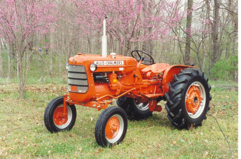
wbecker, That is a very detailed B! The alternator looks great. I believe on a C or CA there is a steering rod pretty close to the sheet metal in this same area. So the smaller Denso would be perfect. As mentioned I am not sure all these Denso type are created equal? I have one that charges at low rpm and one that does not. Regards, Chris
Edited by Sugarmaker - 16 Feb 2020 at 9:55am
|
|
D17 1958 (NFE), WD45 1954 (NFE), WD 1952 (NFE), WD 1950 (WFE), Allis F-40 forklift, Allis CA, Allis D14, Ford Jubilee, Many IH Cub Cadets, 32 Ford Dump, 65 Comet.
|
 |
jaybmiller 
Orange Level Access

Joined: 12 Sep 2009
Location: Greensville,Ont
Points: 23192
|
 Post Options Post Options
 Thanks(0) Thanks(0)
 Quote Quote  Reply Reply
 Posted: 16 Feb 2020 at 2:16pm Posted: 16 Feb 2020 at 2:16pm |
gee, do those 'showroom condition' tractors ever see the fields ?? Look to purdy....please ,toss some mud on PDQ !
as for the ammeter vs voltmeter hookup...yeesh they both take 2 wires, so no more aggrevation, it ain't 'rocket science'.
I know 'it's a 'ford vs chevy deal but one has to understand that a voltmeter will never tell you the condition of a battery, just the very,very lightly loaded voltage. An ammeter shows you which way the electrons are flowing and how many are going there.
voltmeters became the 'standard' when higher current demands for vehicles arose. It's far cheaper to make a 'universal' voltmeter than to have a huge assortment of wiring and ammeters needed for the assembly line.
|
|
3 D-14s,A-C forklift, B-112
Kubota BX23S lil' TOOT( The Other Orange Tractor)
Never burn your bridges, unless you can walk on water
|
 |
wbecker 
Orange Level


Joined: 29 Oct 2009
Location: STL
Points: 837
|
 Post Options Post Options
 Thanks(0) Thanks(0)
 Quote Quote  Reply Reply
 Posted: 16 Feb 2020 at 3:12pm Posted: 16 Feb 2020 at 3:12pm |
Jayb, that was when I just finished building this Lowered B with the 6' woods under it, it has been my main mower for several years now so it doesn't look quite so purdy now, it's a working tractor. 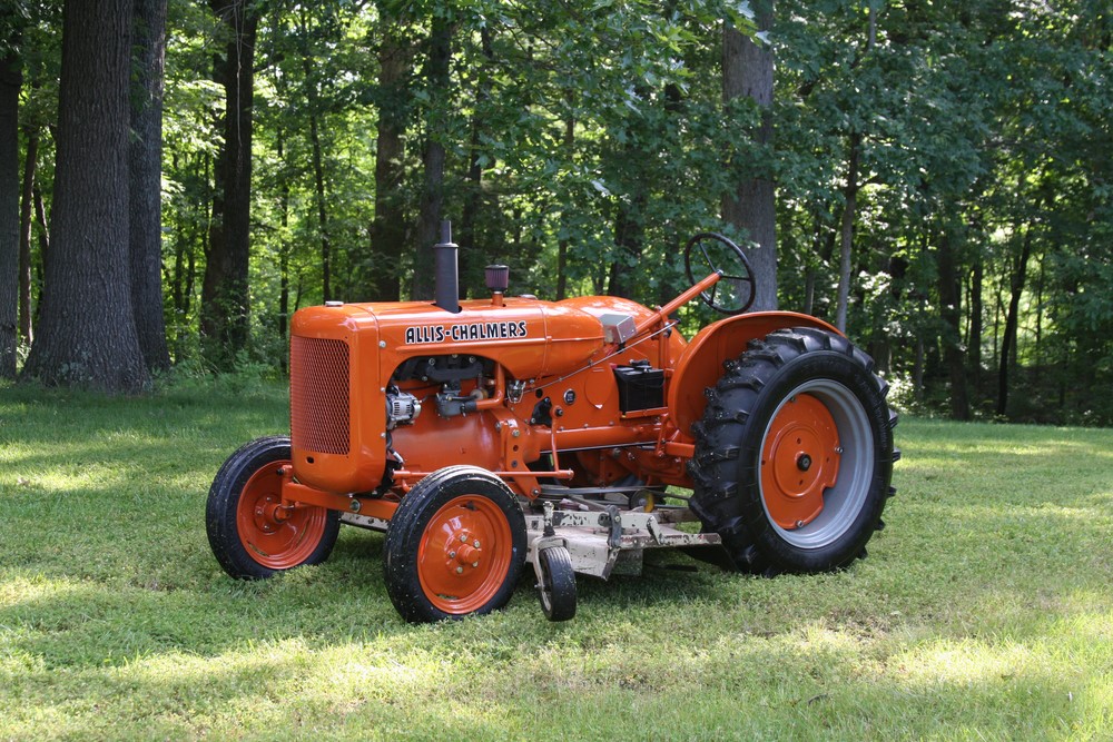
|
|
Allis B, IB, Low B, G, D10, JD M, 8KCAB, C152
|
 |
Steve in NJ 
Orange Level Access


Joined: 12 Sep 2009
Location: Andover, NJ
Points: 11887
|
 Post Options Post Options
 Thanks(0) Thanks(0)
 Quote Quote  Reply Reply
 Posted: 16 Feb 2020 at 4:28pm Posted: 16 Feb 2020 at 4:28pm |
As I said many times, most people don't care what's going in and out of the Battery, all they want to know is if its charging. That's it. All the other stiff with direction and condition of Battery doesn't mean a thing to regular folks. Its important to you engineer types. I'll be the first to admit, I'm not an engineer, I'm a field guy. My draw tester tells me what condition the Battery is in. When I build my wiring systems, (doesn't matter what its for) I keep them simple and safe. Jay's correct about the higher demands of power needed in today's Automobiles and the use of a Voltmeter, but Ammeters were much more dangerous in Automobiles years ago mainly because if a vehicle got into a head on collision or impact to the front of the vehicle to where the main power circuit running into the cabin to supply power inside the vehicle got smashed or crushed in the metal, this caused a dead short and fires would start inside the cabin of the vehicles equipped with Ammeters and set the dashboard insulation a blazin'. I've seen many a vehicle over my 50 years of being a gas/diesel mechanic working on vehicles where the dashboards or complete interiors caught fire. That Battery will supply every bit of amerage it has in it till its dead. And all the while its feeding fuel (current) to the fire....
Steve@B&B BTW, Bill that little lowered B is awesome!! 
|
|
39'RC, 43'WC, 48'B, 49'G, 50'WF, 65 Big 10, 67'B-110, 75'716H, 2-620's, & a Motorhead wife
|
 |
AaronSEIA 
Orange Level

Joined: 11 Sep 2009
Location: Mt Pleasant, IA
Points: 2557
|
 Post Options Post Options
 Thanks(0) Thanks(0)
 Quote Quote  Reply Reply
 Posted: 16 Feb 2020 at 4:52pm Posted: 16 Feb 2020 at 4:52pm |
Now we're getting in the weeds, but...if an ammeter and volt meter both are wired identical, why will the ammeter discharge the battery if destroyed in a wreck and the voltmeter not? Assuming the worst doesn't happen, why not just flip the wires on the ammeter for - ground and be done with it? AaronSEIA
|
 |
jaybmiller 
Orange Level Access

Joined: 12 Sep 2009
Location: Greensville,Ont
Points: 23192
|
 Post Options Post Options
 Thanks(0) Thanks(0)
 Quote Quote  Reply Reply
 Posted: 16 Feb 2020 at 5:14pm Posted: 16 Feb 2020 at 5:14pm |
'historically' all the power from the battery went to an ammeter and then to a fuse and then to lights, ignition, etc. Any short At or AFTER the ammeter and before the fuse, allows ALL current( power) from the battery to go to ground. That's how fires and bad things can happen. The safer wiring would be battery->PRIMARY FUSE-> ammeter -> rest of stuff. If you get a short at the ammeter the PRIMARY FUSE blows(opens) and no fireball. My '97 F150 has TWO primary fuses and then 40 or 50 others afterwards.Frankly it's an insane system and Ford's not the only one doing this. I think one primary is battery to alternator, the other feeds everything else. I'd have to check the schematic. Using a cheap generic voltmeter saves a LOT of $$ big copper wire from battery to dash, labour to install, inventory of proper wires based on model, it gets complicated. A $5 do-all-cars voltmeter gives drivers a gauge, makes them feel happy.. I've never checked but the voltmeter might draw 1 milliamp( 1 /1000th of an amp) to say 'green'. A basic ,old sckool100 amp ammeter,needs, well, 100 amps to make it work.....
If you're going to change from +ve gnd to -ve gnd, you just swap the connections on the ammeter. It's that simple. When you do that you really should( must) replace the OEM fibre washers with nylon ones. Jay
|
|
3 D-14s,A-C forklift, B-112
Kubota BX23S lil' TOOT( The Other Orange Tractor)
Never burn your bridges, unless you can walk on water
|
 |
Steve in NJ 
Orange Level Access


Joined: 12 Sep 2009
Location: Andover, NJ
Points: 11887
|
 Post Options Post Options
 Thanks(0) Thanks(0)
 Quote Quote  Reply Reply
 Posted: 17 Feb 2020 at 7:00am Posted: 17 Feb 2020 at 7:00am |
Jay is right on what he said on everything. Just look at an Ammeter as a flow meter. You need full power running through it to tell you something. A Voltmeter on the other hand just splices into the system and tells you what's going on. In todays brand new cars n' trucks, (Fords in particular) the computer controls the charging system now. If the Battery is "full" the computer reads that from a voltage sense circuit from the Battery. The on board computer then shuts the Alternator off. This was I think for gas mileage reasons. This could easily be read wrong by a mechanic if he or she were checking the charging system with a Volt/Ohm meter and not get a charging rate at the Battery and think the Alternator has an issue. Be careful with these new vehicles. Somethin' else to go wrong that you don't need. The Mfr's are making it tougher all the time for a person with a mechanical backround to work on their own vehicle...  Steve@B&B
|
|
39'RC, 43'WC, 48'B, 49'G, 50'WF, 65 Big 10, 67'B-110, 75'716H, 2-620's, & a Motorhead wife
|
 |
jaybmiller 
Orange Level Access

Joined: 12 Sep 2009
Location: Greensville,Ont
Points: 23192
|
 Post Options Post Options
 Thanks(0) Thanks(0)
 Quote Quote  Reply Reply
 Posted: 17 Feb 2020 at 7:09am Posted: 17 Feb 2020 at 7:09am |
re: The on board computer then shuts the Alternator off. Hmm, does this setup have an electric clutch like the AC compressor ? If not, no savings cause you're still rotating a mass ( rotor ). Having the 'computer' control the alternaotr seems more complicated than just having the internal regulator do the job. Course I always wondered why the 'regulator' is so dang complicated when a $3 'bucket reg' circuit works fine.....
|
|
3 D-14s,A-C forklift, B-112
Kubota BX23S lil' TOOT( The Other Orange Tractor)
Never burn your bridges, unless you can walk on water
|
 |
billyrb 
Bronze Level


Joined: 17 Oct 2020
Location: 30101
Points: 1
|
 Post Options Post Options
 Thanks(0) Thanks(0)
 Quote Quote  Reply Reply
 Posted: 17 Oct 2020 at 9:38pm Posted: 17 Oct 2020 at 9:38pm |
|
|
 |


 Topic Options

 Post Options
 Thanks(0)


 Steve in NJ wrote:


