| Author |
 Topic Search Topic Search  Topic Options Topic Options
|
Les Kerf 
Orange Level

Joined: 08 May 2020
Location: Idaho
Points: 740
|
 Post Options Post Options
") Thanks(0) Thanks(0)
 Quote Quote  Reply Reply
 Posted: 22 Jul 2024 at 11:58pm Posted: 22 Jul 2024 at 11:58pm |
") Dale (Stonelick) wrote: Dale (Stonelick) wrote:
... I used the light to test for amperage discharge - but none was noted... |
Was this with engine running?
If the engine is not running with the light on and there is no discharge indicated on the ammeter, then it is either wired incorrectly or the ammeter is faulty.
If the engine is running at high idle with a light on then a properly functioning system will not show a discharge because the generator will carry the load. It may show a charge occurring, depending on how many lights are burning.
I am not convinced that your wiring is correct.
|
 |
|
Sponsored Links
|
|
|
Phil48ACWC
Silver Level


Joined: 17 Jan 2013
Location: Vermont
Points: 283
|
Post Options
Thanks(0)
Quote Reply
Posted: 23 Jul 2024 at 5:59am |
|
In 1999 I completely converted my WC to 12V with a Delco 10SI alternator with internal solid state regulator. The original 6V starter works just fine with 12V. Best thing I ever did to the electrical system. Never had any problems in 25 years and this tractor is used year round. All I had to do was adjust the belt tension. Just do it and don't look back. In the long run it will save you time, money, and aggravation. Especially aggravation.
Edited by Phil48ACWC - 23 Jul 2024 at 6:24am
|
|
jaybmiller
Orange Level Access
Joined: 12 Sep 2009
Location: Greensville,Ont
Points: 22089
|
Post Options
Thanks(0)
Quote Reply
Posted: 23 Jul 2024 at 6:15am |
FWIW IF you're into 'restoring' the tractor to original, then get a 2 wire genny and a cutout relay.
Be sure to monitor acid level in 6 v battery, use 'fat cables, and keep everything clean. Cutout relay can be a diode in the OEM relay shell.
If you want a super reliable tractor, upgrade to 12 volt alternator/battery system. Cheap battery, can upgrade lights to LEDs, EASY to jump start car from tractor,can add a winch, etc. If you use the CS130 series or baby Denso ,they fit/look 'better'.
|
|
3 D-14s,A-C forklift, B-112
Kubota BX23S lil' TOOT( The Other Orange Tractor)
Never burn your bridges, unless you can walk on water
|
|
Dale (Stonelick)
Bronze Level


Joined: 13 Jun 2019
Location: Stonelick, Ohio
Points: 179
|
Post Options
Thanks(0)
Quote Reply
Posted: 23 Jul 2024 at 1:54pm |
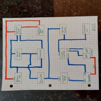
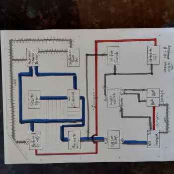
Steve: I had an earlier 10 AMP reading. Better grounding of the instrument panel and another generator FLASH seemed to be the only thing I did to bring it down to 4-5 AMPS. I do have a problem with inconsistent AMP readings - maybe it is a grounding problem? I installed (earlier) a new 16 gauge wire from FLD to resistor (the prior 12 volt regulator didn’t have one). I’ll test it with a 14 gauge wire to see if it makes a difference. Les Kerf: Lights are ON both when ignition switch is ON (engine not running) and when engine is running - on all three light switch positions. Thanks for noting that the ammeter should show no discharge with lights ON and engine running. My problem is I get the same 4 AMP reading both when the lights are wired and when they are not wired. Although the Ammeter reads HOT on both terminals, maybe it is bad. I’m pretty sure the light switch has a problem. I diagramed my wiring as best I could - see picture below. I can’t see any variance when compared to the published diagrams(??). Phil48 and jaybmiller: I’ve got too much invested in the 6 volt system to change it now. Steve B. helped me convert my Allis CA to 12 volt - I agree that it’s been trouble free.
|
|
1951 CA - 1944 C - 1949 B - Kubota M6800
|
|
steve(ill)
Orange Level Access
Joined: 11 Sep 2009
Location: illinois
Points: 79586
|
Post Options
Thanks(0)
Quote Reply
Posted: 23 Jul 2024 at 4:00pm |
|
If your amp guage is good, then 4 amps is reasonable. Why you can get 4 amps WITH and WITHOUT the resistor is questionable. Your light switch is no good, and wireing might also be questionable... You can follow the drawing, and still have a shorted wire on the switch terminals, or sharp edge of box, etc.
Edited by steve(ill) - 23 Jul 2024 at 4:04pm
|
|
Like them all, but love the "B"s.
|
|
Les Kerf
Orange Level
Joined: 08 May 2020
Location: Idaho
Points: 740
|
Post Options
Thanks(0)
Quote Reply
Posted: 24 Jul 2024 at 1:37am |
Dale (Stonelick) wrote:
...
... My problem is I get the same 4 AMP reading both when the lights are wired and when they are not wired.
Although the Ammeter reads HOT on both terminals, maybe it is bad... |
I asked previously if the ammeter shows discharge when the lights are on with engine NOT running but you did not answer directly. The reason for asking is to determine if the ammeter is functioning with anywhere near reasonable accuracy. We aren't expecting ultra precision, just ballpark.
With engine off, lights on, and ignition switch on, you should see maybe 4 amps to even 8-10 amps discharge. You may need to bump the engine a bit to get the points closed for this reading. Please do this test and let us know what you find. I look for the discharge-charge-oil pressure indication every time I start my tractor, it's just an automatic reflex; the needle should go down, then it should go up.
Dale (Stonelick) wrote:
I diagramed my wiring as best I could - see picture below. I can’t see any variance when compared to the published diagrams(??). |
The lower half of your diagram looks ok but the upper half is just weird.
Ammeter + should not go between the solenoid and starter. Battery hot, ammeter, and starter button hot can all go to the solenoid hot (big terminal). Starter button control goes to solenoid small terminal. The other solenoid big terminal goes to the starter.
Erase that weird short blue line at the top of the starter and move the ammeter to the hot side of the solenoid.
|
|
steve(ill)
Orange Level Access
Joined: 11 Sep 2009
Location: illinois
Points: 79586
|
Post Options
Thanks(0)
Quote Reply
Posted: 24 Jul 2024 at 8:28am |
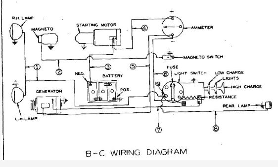
back a ways i posted a color version of the wire diagram.. maybe the Original drawing would help...
|
|
Like them all, but love the "B"s.
|
|
Dale (Stonelick)
Bronze Level
Joined: 13 Jun 2019
Location: Stonelick, Ohio
Points: 179
|
Post Options
Thanks(0)
Quote Reply
Posted: 24 Jul 2024 at 2:41pm |
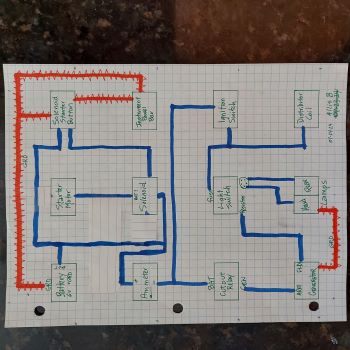
Steve: I ran 12 gauge wire from FLD to Resistor - no change. I’ll keep looking for possible grounding issues. Do you have a wiring diagram that includes a starter solenoid and start button? Les Kerf: LIGHT WIRED: Key ON - engine NOT running: Light comes ON when key is on Light stays ON using all 3 LS positions Read 0/0/0 AMPS on all 3 LS positions Cannot detect any Discharge, since lights are always ON
Key ON - engine running: same as above, except with 4/4/4 AMP reading
LIGHT NOT WIRED: Key ON - engine NOT running: 0/0/0 AMP reading Key ON - engine running: Read 4/4/4 AMPS on all 3 LS positions
WIRING DIAGRAM: You are correct. I retraced wiring and revised my diagram (see below) I noted that the 6 volt solenoid has a “BAT” label on the terminal that I wired to the starter motor. When I reversed the wiring, the starter was dead. I did notice this “mislabel” when I installed this new solenoid several months ago (when I had the old 12 volt generator and voltage regulator). I just figured the mislabeling was due to cheap Chinesium parts (?)
My current plan is to live with what I got - 4/4/4 AMPS - and keep searching for possible ground issues. I’m in a better place now than before, thanks to everyone’s help. I’ll try a NOS light switch if I can find one. I doubt that the new style larger light switch will fit in my cluttered instrument panel box.
|
|
1951 CA - 1944 C - 1949 B - Kubota M6800
|
|
Dale (Stonelick)
Bronze Level
Joined: 13 Jun 2019
Location: Stonelick, Ohio
Points: 179
|
Post Options
Thanks(0)
Quote Reply
Posted: 24 Jul 2024 at 2:52pm |
|
|
|
1951 CA - 1944 C - 1949 B - Kubota M6800
|
|
Les Kerf
Orange Level
Joined: 08 May 2020
Location: Idaho
Points: 740
|
Post Options
Thanks(0)
Quote Reply
Posted: 24 Jul 2024 at 6:26pm |
Dale (Stonelick) wrote:
LIGHT WIRED: Key ON - engine NOT running: Light comes ON when key is on Light stays ON using all 3 LS positions Read 0/0/0 AMPS on all 3 LS positions
|
Your ammeter appears to be faulty, if so, then most of your previous efforts are for naught. Please run the following test: Disconnect the ammeter from EVERYTHING. Using jumper wires, connect your headlight in series with the ammeter and battery and read the amperage. Then do the same test but reverse the polarity. The only components in this test are the battery, ammeter, light, and jumper wires. Please report your findings.
|
|
Alberta Phil
Orange Level

Joined: 13 Sep 2009
Location: Alberta, Canada
Points: 3706
|
Post Options
Thanks(0)
Quote Reply
Posted: 24 Jul 2024 at 7:05pm |
|
Steve at B&B can rebuild your original light switch if you still have it. If not he may have some rebuilt ones in stock. He's done a few for me for my fleet and they all came back like new!
|
|
Dale (Stonelick)
Bronze Level
Joined: 13 Jun 2019
Location: Stonelick, Ohio
Points: 179
|
Post Options
Thanks(0)
Quote Reply
Posted: 25 Jul 2024 at 8:35am |
The light came ON under both tests - alternating ammeter polarities (which I took to mean switching jumper wires on ammeter terminals) - with all other wires disconnected. What do you conclude with regard to the ammeter?
Not sure exactly what you meant by "in series". I just ran a jumper from Battery to ammeter terminal, and another jumper from Light to other ammeter terminal.
Thanks for your help.
|
|
1951 CA - 1944 C - 1949 B - Kubota M6800
|
|
Les Kerf
Orange Level
Joined: 08 May 2020
Location: Idaho
Points: 740
|
Post Options
Thanks(0)
Quote Reply
Posted: 25 Jul 2024 at 3:48pm |
Dale (Stonelick) wrote:
The light came ON under both tests - alternating ammeter polarities (which I took to mean switching jumper wires on ammeter terminals) - with all other wires disconnected. What do you conclude with regard to the ammeter? |
Ummm... nothing. I should have mentioned that the purpose of the test is to see what the ammeter actually reads in both directions. It should read something like 3-4 amps discharge one way and 3-4 amps charge the other way. If it doesn't read the same amount both ways then the gauge is faulty
Dale (Stonelick) wrote:
Not sure exactly what you meant by "in series". I just ran a jumper from Battery to ammeter terminal, and another jumper from Light to other ammeter terminal.
Thanks for your help. |
Series means all of the current flows through one device and then through the next.
|
|
Dale (Stonelick)
Bronze Level
Joined: 13 Jun 2019
Location: Stonelick, Ohio
Points: 179
|
Post Options
Thanks(0)
Quote Reply
Posted: 25 Jul 2024 at 5:44pm |
It reads +2 amp and -2 amp the other way. So the ammeter appears to be good?
If I run same test, but with the light switch between the ammeter and light, suppose it would show that the light stays on using each of the 3 light switch positions. Something I already know. Maybe I can find a new switch with a resistor that fits my instrument box at one of the upcoming tractor shows in my area.
|
|
1951 CA - 1944 C - 1949 B - Kubota M6800
|
|
Les Kerf
Orange Level
Joined: 08 May 2020
Location: Idaho
Points: 740
|
Post Options
Thanks(0)
Quote Reply
Posted: 25 Jul 2024 at 6:47pm |
Dale (Stonelick) wrote:
It reads +2 amp and -2 amp the other way. So the ammeter appears to be good? ... |
Ok, now we are getting somewhere.  That gives us confidence that the ammeter can be trusted.
Now, let's try another experiment. You have proven that the light draws about 2 amps; let's use it instead of the resistor to control the generator field in an effort to prove the actual output of the generator. This should let you know if you really need to do any more work on the generator.
Leave the light switch completely disconnected.
Connect the ammeter directly to the output of the cutout relay, then directly to the battery.
Connect one side of the light to the field terminal on the generator, connect the other side to ground.
Use a jumper wire to energize the ignition (unless it's a magneto).
It is important to NOT use any of the original wiring in case there are problems such as shorting, poor connections, etc. This is intended to test the generator itself.
Run the engine at high idle, the light should be lit. Note the Volts and Amps.
At high idle, short the field terminal to ground, the light should go out. Note the Volts and Amps (they should both increase).
Vary the engine speed down to idle and see what happens ( the Volts and Amps should decrease, at some point the cutout should open and Amps should go to zero).
|
|
Dale (Stonelick)
Bronze Level
Joined: 13 Jun 2019
Location: Stonelick, Ohio
Points: 179
|
Post Options
Thanks(0)
Quote Reply
Posted: 25 Jul 2024 at 9:10pm |
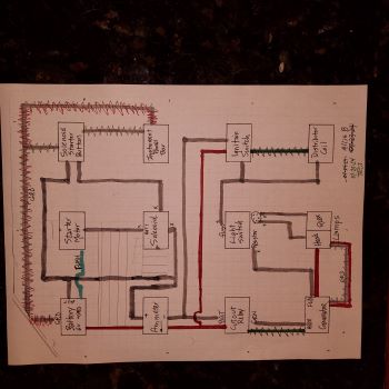
Les - before I try to run test, wanted to make sure the wiring is okay in the picture below:
1. Red jumper wires are those you suggested 2. I added two squiggly dark green jumper wires: from Cutout/GEN to Genny/ARM, and from Ignition Switch to Distributor/Coil. Are these correct for this test? 3. I kept the GRD wire from Battery to Instrument Panel 4. To spin the Starter Motor to start engine, I can FLASH it from the Battery until it starts
Let me know if this seems correct to you, or if something needs to change.
|
|
1951 CA - 1944 C - 1949 B - Kubota M6800
|
|
Les Kerf
Orange Level
Joined: 08 May 2020
Location: Idaho
Points: 740
|
Post Options
Thanks(0)
Quote Reply
Posted: 26 Jul 2024 at 9:31am |
Dale (Stonelick) wrote:
Les - before I try to run test, wanted to make sure the wiring is okay in the picture below: |
Hmmm... The intent of this test is to simulate taking the generator to a shop and having it checked out on a test stand. Since I do not own a test stand, I just use the tractor (or vehicle) as it already has a generator mount and a means of spinning the unit under test.
The important thing to remember is that if you were to actually take the generator to a shop, they wouldn't have any of the wiring, etc. that is on your tractor that may interfere with the test. In order to accurately test/troubleshoot something, it is necessary to eliminate as many things as possible that may interfere with the test.
Visualize how a shop would set up the generator for testing; they would have a mount, a means to spin it, a battery, an ammeter, and a voltmeter. They would also need a way to energize and control the field. And nothing else.
Dale (Stonelick) wrote:
... from Cutout/GEN to Genny/ARM |
You do need this.
Dale (Stonelick) wrote:
and from Ignition Switch |
I would leave the ignition switch completely out of the circuit
Dale (Stonelick) wrote:
to Distributor/Coil. |
I would use a dedicated jumper wire directly to the battery
Dale (Stonelick) wrote:
3. I kept the GRD wire from Battery to Instrument Panel |
This won't hurt anything, it is irrelevant to this test because everything is being bypassed.
Dale (Stonelick) wrote:
4. To spin the Starter Motor to start engine, I can FLASH it from the Battery until it starts |
Yup.
Of course the battery needs to be grounded and also connected to the starter/solenoid
I realize this seems like a lot of fiddling around (it is) but once it is all set up it's sorta fun to play with the field and observe how the outputs change. You will be manually simulating the action of a voltage regulator, albeit much slower and with less precision.
Have fun!
|
|
Dale (Stonelick)
Bronze Level
Joined: 13 Jun 2019
Location: Stonelick, Ohio
Points: 179
|
Post Options
Thanks(0)
Quote Reply
Posted: 26 Jul 2024 at 5:38pm |
Got it wired for the test - not sure how. See wiring picture. BLUE wire: used same existing wiring (too many wires for me to jump). RED wire: new Jumper wires. “X” out faded: disconnected previous wiring. Reading with Engine Running | 1st Test (1) | 2nd Test (2) | 3rd Test (3)
|
|---|
AMP
| 7 | 15 | 5 - 3 | VOLT | 7.60 | 8.65 | 6.84 |
|
|
|
|
High idle. Light ON. Light would fade when idle down. FLD terminal grounded. High idle. Light OFF. FLD terminal grounded. Low idle. Light OFF. AMPs only dropped from 5 to 3 (not zero)
What Is the conclusion: is Generator and wiring working properly?
|
|
1951 CA - 1944 C - 1949 B - Kubota M6800
|
|
Les Kerf
Orange Level
Joined: 08 May 2020
Location: Idaho
Points: 740
|
Post Options
Thanks(0)
Quote Reply
Posted: 26 Jul 2024 at 6:36pm |
Dale (Stonelick) wrote:
Got it wired for the test - not sure how. See wiring picture. BLUE wire: used same existing wiring (too many wires for me to jump). RED wire: new Jumper wires. “X” out faded: disconnected previous wiring.
Reading with Engine Running | 1st Test (1) | 2nd Test (2) | 3rd Test (3)
|
|---|
AMP
| 7 | 15 | 5 - 3 | VOLT | 7.60 | 8.65 | 6.84 |
|
|
|
|
High idle. Light ON. Light would fade when idle down. FLD terminal grounded. High idle. Light OFF. FLD terminal grounded. Low idle. Light OFF. AMPs only dropped from 5 to 3 (not zero)
What Is the conclusion: is Generator and wiring working properly? |
Looks to me like you have a good, strong generator. If it were mine, I would put an "A" circuit voltage regulator on it (actually, I would build my own regulator, but let's not go there just yet).
Now, you just need to decide what to do about your faulty light switch.
|
|
Les Kerf
Orange Level
Joined: 08 May 2020
Location: Idaho
Points: 740
|
Post Options
Thanks(0)
Quote Reply
Posted: 26 Jul 2024 at 10:12pm |
Dale (Stonelick) wrote:
... (c) new Steiner #ABC152 6 volt with 4 terminals, still in box - never wired and never installed... |
Looks like you already own the solution
|
|
jaybmiller
Orange Level Access
Joined: 12 Sep 2009
Location: Greensville,Ont
Points: 22089
|
Post Options
Thanks(0)
Quote Reply
Posted: 27 Jul 2024 at 6:24am |
replace the 6 decade old switch.. for fun, replace the open wire wound resistor with an enclosed one for real fun, replace mechanical guts of regulator with 'solid state devices'
though what you have works fine according to the numbers.
|
|
3 D-14s,A-C forklift, B-112
Kubota BX23S lil' TOOT( The Other Orange Tractor)
Never burn your bridges, unless you can walk on water
|
|
Dale (Stonelick)
Bronze Level
Joined: 13 Jun 2019
Location: Stonelick, Ohio
Points: 179
|
Post Options
Thanks(0)
Quote Reply
Posted: 27 Jul 2024 at 11:10am |
Thank you Les. And thanks to everyone else for your helpful comments and suggestions. A quick recap of problems, missteps, corrections and solutions: (1) originally had no amp reading unless a jump around voltage regulator, (2) multiple wiring problems, (3) replaced generator [with a used generator], (4) replaced voltage regulator with a cutout relay, (5) in retrospect, it seems that the tractor might have been wired as a 12 volt system, (6) the need for a good ground to the instrument panel box, (7) remembering to FLASH from BAT to GEN terminal after each modification, (8) positive test results on Generator, Ammeter and wiring, (9) now getting 4 amps at high idle under all three light switch positions, and (10) conclusion that the Light Switch needs to be replaced. One thing I should have done early on, is to install a battery disconnect switch. Thanks again.
|
|
1951 CA - 1944 C - 1949 B - Kubota M6800
|
|
Les Kerf
Orange Level
Joined: 08 May 2020
Location: Idaho
Points: 740
|
Post Options
Thanks(0)
Quote Reply
Posted: 27 Jul 2024 at 12:33pm |
Dale (Stonelick) wrote:
Thank you Les. And thanks to everyone else for your helpful comments and suggestions. |
And thank you for your feedback and diligent testing. So often we never get to know the results
|
|