can a cut-out relay be repaired?
Printed From: Unofficial Allis
Category: Allis Chalmers
Forum Name: Farm Equipment
Forum Description: everything about Allis-Chalmers farm equipment
URL: https://www.allischalmers.com/forum/forum_posts.asp?TID=202185
Printed Date: 23 Nov 2024 at 4:40pm
Software Version: Web Wiz Forums 11.10 - http://www.webwizforums.com
Topic: can a cut-out relay be repaired?
Posted By: Dale (Stonelick)
Subject: can a cut-out relay be repaired?
Date Posted: 08 Jul 2024 at 2:53pm
The picture is from a 1949 Allis B #96201. I assume it's bad because I can only get an ammeter reading by using a jumper around the relay. The name on the relay is "Echlin". I could find no name or serial number on the generator.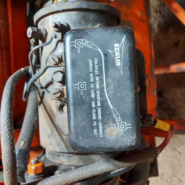 ------------- 1951 CA - 1944 C - 1949 B - Kubota M6800 |
Replies:
Posted By: DiyDave
Date Posted: 08 Jul 2024 at 3:22pm
Yes it can be repaired, but not for the cost of a new one. That regulator should be available at any Napa store... ------------- Source: Babylon Bee. Sponsored by BRAWNDO, its got what you need! |
Posted By: DSeries4
Date Posted: 08 Jul 2024 at 3:27pm
|
Replace it. They are cheap. ------------- '49 G, '54 WD45, '55 CA, '56 WD45D, '57 WD45, '58 D14, '59 D14, '60 D14, '61 D15D, '66 D15II, '66 D21II, '67 D17IV, '67 D17IVD, '67 190XTD, '73 620, '76 185, '77 175, '84 8030, '85 6080 |
Posted By: Dale (Stonelick)
Date Posted: 08 Jul 2024 at 4:08pm
|
Thanks. I thought they might be easy to fix after looking at the internals. ------------- 1951 CA - 1944 C - 1949 B - Kubota M6800 |
Posted By: Fred in Pa
Date Posted: 08 Jul 2024 at 5:18pm
|
That is not a cut out ------------- He who dies with the most toys is, nonetheless ,still dead. If all else fails ,Read all that is PRINTED. |
Posted By: Dale (Stonelick)
Date Posted: 08 Jul 2024 at 5:52pm
|
Fred: Do you know what it could be? I told Brenda K at SLE that it was a Voltage Regulator, but she said those aren't used on the Allis B. She was going to check with her shop guys to see what they think. If it's the wrong part, maybe that is why I'm not getting a ammeter reading through it? ------------- 1951 CA - 1944 C - 1949 B - Kubota M6800 |
Posted By: dfwallis
Date Posted: 08 Jul 2024 at 6:06pm
|
It is a regulator. Hopefully there's a part number on it somewhere. ------------- 1952 CA13092 |
Posted By: jaybmiller
Date Posted: 08 Jul 2024 at 6:09pm
|
Google shows it as an Echlin 27-31 , 12 volt voltage regulator. https://www.ebay.ca/itm/294090624417" rel="nofollow - https://www.ebay.ca/itm/294090624417 Since all B's were 6 volt.... begs the question... is yours 6 or 12 volt ? Can you read tag on the generator ??
------------- 3 D-14s,A-C forklift, B-112 Kubota BX23S lil' TOOT( The Other Orange Tractor) Never burn your bridges, unless you can walk on water |
Posted By: mdm1
Date Posted: 08 Jul 2024 at 6:36pm
|
Kinda neat they show you how to polarize it. ------------- Everything is impossible until someone does it! WD45-trip loader 1947 c w/woods belly mower, 1939 B, #3 sickle mower 1944 B, 2 1948 G's. Misc other equipment that my wife calls JUNK! |
Posted By: steve(ill)
Date Posted: 08 Jul 2024 at 6:50pm
|
a cutout would have TWO TERMINALS and ONE COIL inside...( and be used on a 6 volt systesm) .... a VOLTAGE REGULATOR would have 3 terminals ( or 4) and 2 -3 coils inside..( and would be used on a 12 v system.. but some 6v have regulators).
------------- Like them all, but love the "B"s. |
Posted By: PaulB
Date Posted: 08 Jul 2024 at 7:30pm
A NAPA store actually have a tractor part  That's the best laugh I've had all day. For anything made before this century even if the snot nose punks even know want you're talking about the best they can do it the old Central Tractor line before they went out of business "We can order it" . Going to a NAPA store is about as much of a waste of time as expecting to find what you need at a TSC. That's the best laugh I've had all day. For anything made before this century even if the snot nose punks even know want you're talking about the best they can do it the old Central Tractor line before they went out of business "We can order it" . Going to a NAPA store is about as much of a waste of time as expecting to find what you need at a TSC.------------- If it was fun to pull in LOW gear, I could have a John Deere. Real pullers don't have speed limits. If you can't make it GO... make it SHINY |
 DiyDave wrote:
Posted By: Steve in NJ
Date Posted: 08 Jul 2024 at 7:34pm
|
That is a voltage regulator. Look on the bottom of the unit. There's probably a part number stenciled on it. Dave is right. Echlin is part of Napa. Look real close on that Gennie. It may have "12V" stamped on the chassis. (body) Steve@B&B ------------- 39'RC, 43'WC, 48'B, 49'G, 50'WF, 65 Big 10, 67'B-110, 75'716H, 2-620's, & a Motorhead wife |
Posted By: Dale (Stonelick)
Date Posted: 08 Jul 2024 at 8:02pm
|
Some further messy information: 1.could find no part number on regulator. Jay's eBay picture shows it stamped in blue ink on galvanized base next to BAT terminal. My base is painted black, with no part number visible. 2. I must have a regulator for a 12 volt system based on (a) Jay's link to the 12 volt eBay part, and (b) mine has 3 terminals and 3 coils inside, which must confirm that it is a 12 volt part as per Steve's info. 3. I believe my Allis B wants to be a 6 volt (a) I replaced the old dead battery with a 6 volt [I assume the old battery was 6 volt - but maybe not] (b) It has a generator, not an alternator, (c) the battery cables are heavier than the CA that Steve B helped me convert to 12 volt, (d) BUT I had to replace the 12 volt solenoid with a 6 volt to get the starter to work, (e) BUT I had to replace the 12 volt coil with a 6 volt to get the spark plugs to fire, (f) BUT the regulator is a 12 volt, (g) maybe the old deceased owner was in process of converting to a 12 volt system? 4. I cannot find a name or serial number on the generator. 5. An interesting find when I wired brushed the 3 terminals to get a better connection. (a) the now visible FLD terminal was connected to the generator's positive post with 16g wire. (b) the now visible ARM terminal was connected to the generator's negative post wire heavier gauge black wire. I think the FLD and ARM wires are reversed - can anyone confirm? 6. I think I flashed the FLD terminal several times to the positive BAT, because.... Obviously I believe this was wrong - should flash the ARM terminal to BAT. At first light tomorrow, I'll try to right some of these wrongs. Maybe it will help, but maybe not. ------------- 1951 CA - 1944 C - 1949 B - Kubota M6800 |
Posted By: steve(ill)
Date Posted: 08 Jul 2024 at 8:11pm
|
you need to figure out what you WANT... THe old 6 volt systems were POSITIVE GROUND.. thats why some of your wires might look BACKWARD.... Most of the NEW 12 v systems a NEGATIVE GROUND..... a BATTERY has a series of 2 volt CELLS.. If you have 3 round CAPS on top, you have 6v battery... If you have 6 round CAPS ( or two long ones over 3 cells each )... then you have a 12V battery. Better figure out FIRST what you want to do... stick with the OLD 6v or go with the NEW 12 V ...... 12v battery, 12v coil, 12v regulator... all go TOGETHER.... dont mix and match. It IS POSSIBLE that they guy took a 6v REGULATOR and put on inplace of the OLD CUT OUT...... How does it CRANK and START with the 6v battery ?? If that is acceptable , then maybe you need a 6v REGULATOR...... The OLD LIGHT SWITCH had a resistor on it to act as an "amp output regulator" along with the CUTOUT.... the new "REGULATOR" would no longer use the light switch resistor...
------------- Like them all, but love the "B"s. |
Posted By: steve(ill)
Date Posted: 08 Jul 2024 at 8:16pm
MOST 6v systems have the POSITIVE side of the battery GROUNDED... YOURS ??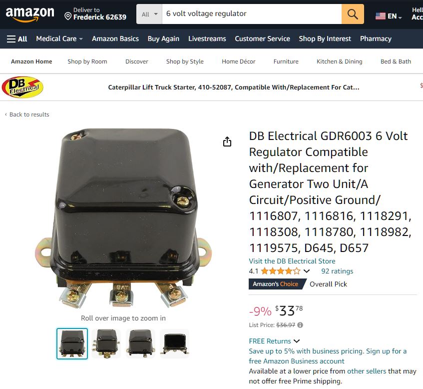 ------------- Like them all, but love the "B"s. |
Posted By: steve(ill)
Date Posted: 08 Jul 2024 at 8:26pm
|
discussion with a drawing.... https://www.allischalmers.com/forum/allis-c-positive-ground-wiring-diagram_topic179994.html" rel="nofollow - https://www.allischalmers.com/forum/allis-c-positive-ground-wiring-diagram_topic179994.html ------------- Like them all, but love the "B"s. |
Posted By: Dale (Stonelick)
Date Posted: 08 Jul 2024 at 11:00pm
|
Steve: Yes, mine has a positive ground. I'm happy with the 6 volt system and it seems to start and run well, after spending some time and money on it. So I plan to keep it 6 volt. My next step in trying to get the generator to charge the battery, is to correct the FLD and ARM wiring on the 12 volt voltage regulator. So just to clarify since it's a 6 volt positive ground: the ARM terminal should be connected to the positive post on the generator, and the FLD terminal should be connected to the ground post on the generator. I am not hopeful that this will solve my problem, since it's 12 volt and not a 6 volt regulator. I'll then see if Brenda Knauss from Sandy Lake Equip can determine what replacement 6 volt Cutout Relay I would need to be compatible with my unknown generator model. If that fails, I'll take my generator and voltage regulator to a generator repair shop and see if they can sort out what I need to make it work. I read through the link you sent and noted that OP said he replaced his cutout relay with a voltage regulator, as he understood the regulator replaced the need for a 3 position light switch (1st position is low charge, 2nd position is higher charge, and 3 position is light switch). Again, thanks to everyone for their help. ------------- 1951 CA - 1944 C - 1949 B - Kubota M6800 |
Posted By: Fred in Pa
Date Posted: 09 Jul 2024 at 6:29am
|
To save wasting time n money ,take generator to a good electric shop ,and go from there . Don't get all confused to point you make a bigger mess . ------------- He who dies with the most toys is, nonetheless ,still dead. If all else fails ,Read all that is PRINTED. |
Posted By: steve(ill)
Date Posted: 09 Jul 2024 at 8:53am
|
I read through the link you sent and noted that OP said he replaced his cutout relay with a voltage regulator, as he understood the regulator replaced the need for a 3 position light switch (1st position is low charge, 2nd position is higher charge, and 3 position is light switch). YEs, that is correct.. A CUTOUT needs the light switch resistor.. A VOLTAGE REGULATOR replaces both of them... I would BET that your present regulator is a 6V type... You need something similar. A local shop MIGHT be a good idea to ease your mind. They will get you something similar to the picture i posted above. ------------- Like them all, but love the "B"s. |
Posted By: steve(ill)
Date Posted: 09 Jul 2024 at 8:59am
DO NOT BUY THIS.... just showing you such an animal does exist... 6V pos ground.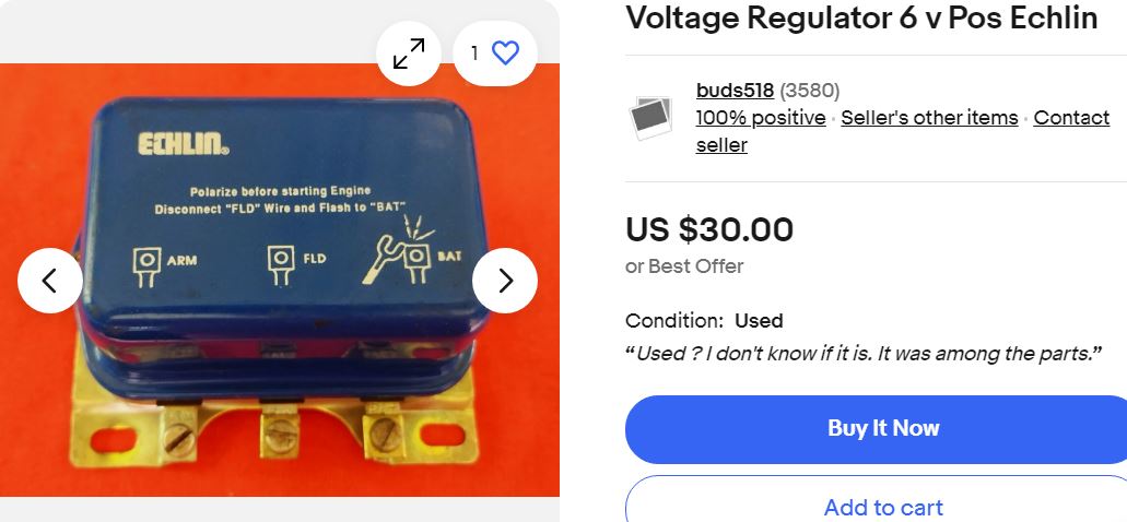 ------------- Like them all, but love the "B"s. |
Posted By: dfwallis
Date Posted: 09 Jul 2024 at 10:51am
|
I bought a 6V regulator from Steiner. I took it and the gen to a shop and he made sure they both worked properly together. And he made sure I knew that you DO NOT need the extra .1 ohm resistor that comes with the kit. The gen/regulator combination supplied the correct voltage and control as-is. I did rewire the switch such that the first position is lights now.
------------- 1952 CA13092 |
Posted By: Dale (Stonelick)
Date Posted: 09 Jul 2024 at 12:28pm
|
Interesting that the "polarize" instructions are different between the 6 volt and the 12 volt regulators. For 12 volt you flash the ARM terminal, and for the 6 volt you flash the FLD terminal. So I have no clue on how to correctly wire a 12 volt regulator, much less a 12 volt regulator on a positive ground with probably a 6 volt generator. I couldn't find any online Echlin wiring instructions. Still waiting on Brenda to see if she has any advise. I'll also try to send message to Steiner tractor. I'll also search to see if there is a generator repair shop close to me. ------------- 1951 CA - 1944 C - 1949 B - Kubota M6800 |
Posted By: dfwallis
Date Posted: 09 Jul 2024 at 12:40pm
The 6V regulator I bought you flash the ARM terminal. ------------- 1952 CA13092 |
Posted By: Les Kerf
Date Posted: 09 Jul 2024 at 12:59pm
Please, please, DO NOT attempt to use a 12 Volt regulator on a 6 Volt battery!  There is no correct way to wire it. There is no correct way to wire it.If you have a 12 Volt battery and a 12 Volt regulator on a 6 Volt generator, the generator will put out 12 volts. For a while. Maybe for a long while. Maybe not.
|
Posted By: Riprock
Date Posted: 09 Jul 2024 at 1:05pm
| The regulator in the ebay picture shows polarizing instructions for a "B" type used by early fords. You removed the field wire and touched it to the bat terminal. Delco used "A" circuit where you use a jumper between arm & Bat terminals to polarize. On a delco if you jumper from fld. terminal to ground the generator should charge wide open, bypassing the regulator. Never touch field to bat on an A circuit. |
Posted By: mdm1
Date Posted: 09 Jul 2024 at 3:52pm
|
Try to find out what make the generator is and get a 6v voltage regulator to match it. You can then use a regular light switch if you have lights. It will charge better and you can leave it 6v. Just a suggestion. ------------- Everything is impossible until someone does it! WD45-trip loader 1947 c w/woods belly mower, 1939 B, #3 sickle mower 1944 B, 2 1948 G's. Misc other equipment that my wife calls JUNK! |
Posted By: steve(ill)
Date Posted: 09 Jul 2024 at 3:56pm
|
Terry is right... I was just showing that Echlin DID make a 6v POSITIVE GROUND voltage regulator... YOU DONT WANT THAT SPECIFIC ONE.. but you DO WANT a 6V. ------------- Like them all, but love the "B"s. |
Posted By: Les Kerf
Date Posted: 09 Jul 2024 at 5:32pm
Excellent post. The original poster showed a photo of an "A" circuit regulator, it is crucial to have the correct type.
|
Posted By: Les Kerf
Date Posted: 09 Jul 2024 at 5:38pm
|
A while back there was a young man posting on here about his WD tractor that had what turned out to be a Ford (?) IIRC, generator scabbed onto it by a previous owner. Never assume! |
Posted By: dfwallis
Date Posted: 09 Jul 2024 at 5:45pm
|
Slightly peripherally, my original switch was completely missing so I bought a rebuilt one from B&B, even though I fully planned to go with a regulator. I wanted to maximize originality with only a few minor exceptions (regulator and some add-ons). The switch rebuild was top notch quality I might add. ------------- 1952 CA13092 |
Posted By: Steve in NJ
Date Posted: 10 Jul 2024 at 10:00am
|
The bestest way and the easiest way to get this system to work is remove the Generator, bring it to a good replicable rebuilder and have him mate the proper VR to the Gennie. What I do in my shop is if the Gennie still has the tag on it, I mate a VR to the Generator part number. I then set the two up on the 881 machine and dial them in together. If no tag, I run/load test the unit to see if there is any output and what it's max. output is. Then I mate the proper VR to the unit and run/load test them together. As for Batteries, Steve is correct. Six volt Batteries have 3 cells. (caps) Twelve volt Batteries have 6 cells. (caps) Easy to remember. If you plan on keeping it 6 volt and you're not using the 3 position switch to control the ground, (charging) mate the proper VR to the Gennie as I mentioned. Have a rebuilder do it for you. It takes all the guess work out.Another thing to keep in mind that's always overlooked. Make sure the fan belt you are using is new or in very good shape. Old dry rotted belts slip causing a no charge issue.... HTH Steve@B&B
------------- 39'RC, 43'WC, 48'B, 49'G, 50'WF, 65 Big 10, 67'B-110, 75'716H, 2-620's, & a Motorhead wife |
Posted By: Riprock
Date Posted: 10 Jul 2024 at 1:30pm
| I took a knock off delco alternator to get it repaired years ago and the guy said they make a 1000 different ones of these, and we can fix 999 of them. I was always impressed how he left himself a way out lol. |
Posted By: steve(ill)
Date Posted: 13 Jul 2024 at 7:47pm
|
Dale, here is a drawing of the ORIGINAL 6 v system with POSITIVE GROUND on your tractor... Note that the "ARMATURE" terminal is the HOT terminal on the generator... that would go to the amp meter then NEGATIVE BATTERY terminal on a POSITIVE GROUND system.. If you have NEGATIVE GROUND, then the HOT TERMINAL is the POSITIVE... That is one problem when discussing 6V systems..... The drawing is also correct that the "A" terminal is toward the OUTSIDE of the tractor and the "F" terminal ( ground to light switch) is toward the ENGINE BLOCK.-- asssuming you had the ORIGINAL GENNY... which you probably do NOT ?? When you get your "REGULATOR", you need to determine how the BATTERY is grounded .. and that will be the "F" terminal.... the "A" to your "G" terminal will be the HOT terminal on the battery..  ------------- Like them all, but love the "B"s. |
Posted By: steve(ill)
Date Posted: 13 Jul 2024 at 7:56pm
I think this is what you are doing.... Make sure your NEW regualtor will work on POSITIVE GROUND... and is 6v...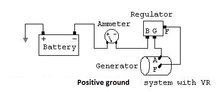 ------------- Like them all, but love the "B"s. |
Posted By: steve(ill)
Date Posted: 13 Jul 2024 at 9:28pm
|
Dale, i was assuming you had the ORIGINAL generator... which does not seem to be the case... The BIGGER of the two terminals is usually the ARMATURE and the SMALLER terminal is the FIELD ( ground).... it would appear your "A" terminal is the one closest to the engine block... from your PHOTO ?? i think this is what is confusing us on "the wires are switched"... 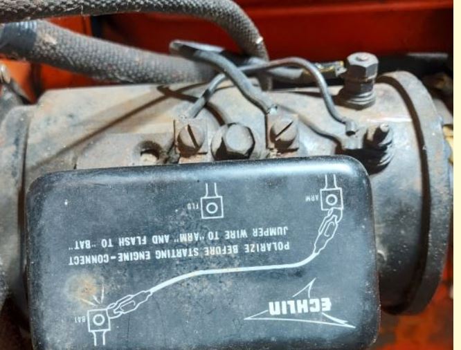 ------------- Like them all, but love the "B"s. |
Posted By: Dale (Stonelick)
Date Posted: 15 Jul 2024 at 5:41pm
|
Eureka! (maybe) The Allis B is now charging at about -5 amps, using an old Allis CA generator. Battery tests a 7.96 volts (6.52 volts when not running) and 7.35 volts at the generator posts. Hopefully the negative amp reading doesn’t mean it’s sucking out the charge. I did try to reverse the ARM/FLD wiring on the generator, but the ammeter read zero. I installed the old Allis CA 6 volt generator that I happened to rediscover (I had taken it off in 1998 not knowing if it worked or not). I was searching for a pulley for an old Allis B generator that I just purchased from a neighbor (he didn’t know if his salvaged generator worked or not). Because I couldn’t remove the pulley from my old Allis CA generator, I just decided to see if it would work on my Allis B. I found a never used cutout relay (in original box) in my tractor stuff. Wrapper shows “R11-F, 6 volt cutout, 617837-3”. It has “2727” stamped on its metal case. Wiring was: GEN cutout terminal to generator ARM (bottom) post, Generator FLD (top post) grounded to small bolt on generator, I used 16 gauge wire for both. I had decided to find a replacement generator, since I couldn’t get the current one to run by jumping it directly to the battery (with the belt removed). Also, I didn’t want to run the risk of burning up the new 6 volt regulator I bought from Steiner. The now unused Steiner regulator is part #ABC152, which is listed as for being for early model Allis D10, D12, etc. Steiner identified what part I needed from the fact that my old Allis B generator has only two brushes, rather than three. This new regulator has four terminals - terminal “L” (lights) would have been unused in my installation. At last resort, I was going to make the 3 hour road trip to the “local” generator shop. Thankfully I avoided this. (maybe) So now I have more excess parts if anyone is interested in them: (a) old D10 6 volt generator that doesn’t seem to work (maybe it needs new brushes?). (b) old Allis B 6 volt generator - don’t know if it works or not. It’s missing pulley, cutout, and wiring. (c) new Steiner #ABC152 6 volt with 4 terminals, still in box - never wired and never installed. (d) old Echlin [NAPA] 3 terminal regulator. Based on info from jaybmiller & Steve, it’s a 12 volt Echlin 27-31 regulator. Don’t know if it works or not. 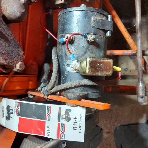 ------------- 1951 CA - 1944 C - 1949 B - Kubota M6800 |
Posted By: steve(ill)
Date Posted: 15 Jul 2024 at 6:55pm
Nice to finally WIN the war !!!  ------------- Like them all, but love the "B"s. |
Posted By: jaybmiller
Date Posted: 15 Jul 2024 at 7:34pm
|
nice to hear someone's winning today (don't ask..) as for the amps... disconnect battery THEN check the ammeter wiring. Odds are it was reversed when someone went -ve ground (the standard today ) from the +ve gnd wiring when the beastie was 'factory fresh'. ------------- 3 D-14s,A-C forklift, B-112 Kubota BX23S lil' TOOT( The Other Orange Tractor) Never burn your bridges, unless you can walk on water |
Posted By: Alberta Phil
Date Posted: 15 Jul 2024 at 7:35pm
|
If it's showing negative charge, just reverse the wires on the back of the ammeter and it should show positive charge. |
Posted By: Les Kerf
Date Posted: 16 Jul 2024 at 12:19am
I am unclear as to how that is wired, it appears you are full-fielding the generator all the time?
|
Posted By: steve(ill)
Date Posted: 16 Jul 2024 at 8:23am
|
yea... your eventually going to need a LIGHT SWITCH RESISTOR.. or a stand alone resistor to cut the charge down... When you GROUND the "F" terminal, you should get 8 amps on an ACURATE GAUGE.... (You might have 5 amps, you might have a little MORE)... Possible to overcharge the battery... Resistor cuts that charge to 2-3 amps constant.. ------------- Like them all, but love the "B"s. |
Posted By: Dale (Stonelick)
Date Posted: 16 Jul 2024 at 2:47pm
|
1. jaybmiller and Alberta Phil: I switched the ammeter wires (single wire on one post and two wires on the other post) and am now getting about +10 AMP reading at low charge (but high RPM). Pulling light switch out to high charge did not move the needle. I guess a negative AMP reading did mean it was actually discharging. Thanks for the advice, but now have to figure out the overcharging issue (see below). 2. Les Kerf: I reviewed the FLD wiring diagrams again and added a 16 gauge wire from the generator FLD post to the resistor wire post on the light switch. I'm now getting 8.42 volts on the battery and 9.80 volts on the generator posts. So I think it's now overcharging. Thanks for the heads up. 3. Steve: As per the above, the system now appears to be overcharging. - too many AMPS and too many VOLTS. I also did note that the operators manual stated it should run at about 3 AMPS, but I don't know if this is at Hi or Low rpm. The light switch does have a resistor. I attached the new FLD wire from generator to the resistor. I attached the wire to the resistor wire end that was easiest to access - could that be the wrong end? My resistor wire design is a little different than what is shown in the diagram. Lastly, I did FLASH the generator and grounded the instrument panel box, which helped a little (see below). Any suggestions as next steps? Maybe (a) defective light switch, (b) defective resistor, (c) wiring to wrong resistor wire end, (d) wrong cutout relay model, (e) remove the new wiring from FLD to light switch resistor, (f) time to take it to a generator shop???? Will appreciate your and other's thoughts on this overcharge problem. 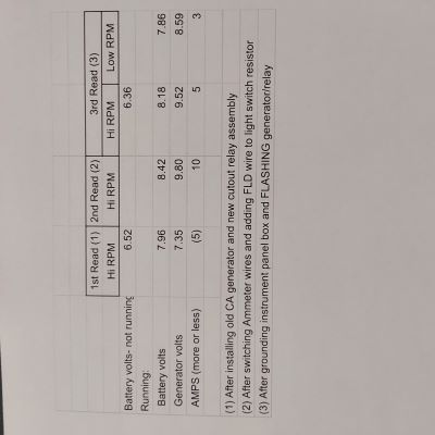 ------------- 1951 CA - 1944 C - 1949 B - Kubota M6800 |
Posted By: steve(ill)
Date Posted: 16 Jul 2024 at 3:45pm
|
THe CUT OUT is ON- OFF... has nothing to do with charge rate.. Just opens the circuit when engine not running... Generator voltage on a 6 volt system will put out about 12 volts... It is the BATTERY that sets the voltage charge.. Kind of like a HEAT SINK.. Remove the battery wire and the generator will put out 12v... a 12v generator will put out 20 v if not REGULATED by the battery...The CHARGE RATE or AMPS is controlled by "how good is the ground wire on the F terminal"... If you got a GREAT ground, then you get 8 amps... if you have a restricted ground ( thru the resistor) then you should get about 3 amps... If you turn on the lights they will pull 3-4 amps so that is why the resistor is not in the circuit when the lights are on. If you GROUND the F terminal the amp gauge should say 8. If you connect the RESISITOR to the F wire and ground the other side, it should say 3 amps. IF you get a LOT MORE VOLTS or AMPS out of the generator, then the generator probably need adjusted / cleaned/ etc.. internally. ------------- Like them all, but love the "B"s. |
Posted By: steve(ill)
Date Posted: 16 Jul 2024 at 4:10pm
|
the sheetmetal cover around the back 2 inches of your generator would lead you to believe it is an older 6v generator.. You THINK it came off a CA... You can take that cover off and LOOK at the brushes and springs pushing on the center shaft. See that everything looks GOOD... You MIGHT have a 3rd brush around the shaft that has a screw and slot that allows it to loosen and ROTATE back and forth.. That ADJUSTMENT is to set the amp/ voltage charge on a simple generator that does not use a voltage regulator....... if you see rust , clud, broken or bent spring, worn brushes, etc, then you need someone to do internal work. 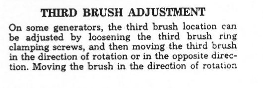 allows you to raise or lower the charge rate.. picture of 3rd brush design below on left. 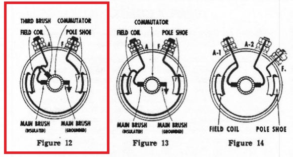 ------------- Like them all, but love the "B"s. |
Posted By: Les Kerf
Date Posted: 16 Jul 2024 at 5:28pm
You need to remove the wire connecting the field to ground at generator, it is full-fielding the generator, thereby driving it to maximum output (overcharging).
|
Posted By: Dale (Stonelick)
Date Posted: 16 Jul 2024 at 8:15pm
|
Less Kerf: I removed the FLD wire to case and got better readings the first time, especially the VOLTS on generator. I tested a second time and got some crazy inconsistent readings. See chart below. Tomorrow I'll put new batteries in the voltmeter, RE-Flash the generator and re-test. Interesting to note that when I pull the light switch all the way out, I never get an increase in charging rate. Could this indicate a faulty switch? Steve: I will try to adjust the 3rd brush as you suggested. What is an acceptable target for battery VOLTS at Hi RPM? I had read once that a battery should test in 7-8 volt range while at rest. Anything in 6-7 volt range indicates a problem. But have no clue what is target for battery running at Hi RPM. Also not sure about the 3 AMP target at Hi or Low RPM. 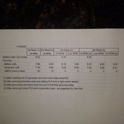 ------------- 1951 CA - 1944 C - 1949 B - Kubota M6800 |
Posted By: steve(ill)
Date Posted: 16 Jul 2024 at 8:51pm
|
I did not realize when you ran the "F" wire to the resistor, you left a second wire from the "F" terminal to ground. ( look at the print above again... only 1 wire on F).... Resistor will do nothing if you have the "F" grounded.. You will get FULL CHARGE.. If you removed the ground and ran the wire to the resistor, and then appears you get random numbers, that means the Resistor is not working, or is not grounded on one side.....I would get that fixed before trying to adjust the 3rd brush.. The resistor has to work to get the LOW AMP CHARGE of 3 amps.... Most of the NUMBERS we discuss will be at hi idle, operating rpm .... you might not get much at idle speed. ------------- Like them all, but love the "B"s. |
Posted By: steve(ill)
Date Posted: 17 Jul 2024 at 12:32pm
|
If you have a spare resistor... wire it to the "F" terminal of the generator and touch the other end of resistor to the case ( GROUND)... That would bypass your wire and switch and be a good test... For voltage, you would like to be right around 7 v... 6.9 to 7.1 or so.... more that 7.4 is too much and will cook the battery... All values are for HI IDLE.. Resistor should also get you down to the 3-4 amp charge range.. Constant charge at 8-9 amps is too much for the battery. ------------- Like them all, but love the "B"s. |
Posted By: Riprock
Date Posted: 17 Jul 2024 at 11:30pm
| Does your tractor currently have a light switch with a resistor or just an on/off or pull type switch without one? As others have said to use a cut-out on the generator your field current through the generator is controlled by the resistor in an original style switch. when your tractor had a regulator on it as in your first post the switch could have been changed or the resistor was bypassed. |
Posted By: Riprock
Date Posted: 17 Jul 2024 at 11:39pm
| I know the poster has already changed the generator but does that generator in the first post look like an auto-lite to anyone else? |
Posted By: Dale (Stonelick)
Date Posted: 18 Jul 2024 at 12:44pm
|
07/18/24
I appreciate everyone’s comments, advice and patience. 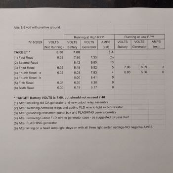 ------------- 1951 CA - 1944 C - 1949 B - Kubota M6800 |
Posted By: steve(ill)
Date Posted: 18 Jul 2024 at 3:35pm
|
If you GROUND the "F" terminal on the generator you will get 8 amps... IF you jumper the "F" terminal to the light switch resistor ( and it is grounded on the OTHER END), you will get 3 amps. If you get the 8 amps with the ground wire, but not the 3 amsp with the resistor / wire... then the resistor is bad... the resistor is not grounded.. the light switch is bad.. the light switch is not grounded... or the light switch BOX is not grounded.... basiclly you have NO GROUND when your using the resistor.. Thats why i said try an extra resistor... another option is to run the wire to the RESISTOR on the light switch and JUMPER the other side of the resistor to a GOOD GROUND... if that works, you know you dont have a good ground on the light switch ( or your using the wrong terminals)... if it does NOT WORK.. then your resistor is junk. A GOOD GROUND test is to take a 2 ft long jumper and connect to the BATTERY + terminal, then touch the LIGHT SWITCH CASE.... and then the LIIGHT SWITCH RESISTOR terminal.... something is BAD at that area.
------------- Like them all, but love the "B"s. |
Posted By: steve(ill)
Date Posted: 18 Jul 2024 at 3:48pm
your switch may look something like this... the SWITCH CASE has to have a GOOD GROUND for everything to work.. If you have paint or rubber bushing on it.. could be a problem.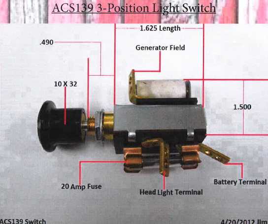 ------------- Like them all, but love the "B"s. |
Posted By: Les Kerf
Date Posted: 18 Jul 2024 at 8:51pm
|
Posted By: Dale (Stonelick)
Date Posted: 19 Jul 2024 at 8:54pm
|
Ran through some of Steve’s suggestions and found that after jumping Resistor to Positive Battery Ground (with headlamp ON) the reading is 5 AMPS and 8.11 volts (both too high). Using the light switch’s high charging position did not result in higher AMP reading. The headlamp remained ON under all three light switch positions, which is another problem. Ran the test again with the headlamp disconnected. Low charge was at zero AMPS and high charge was at 5 AMPS and 8.29 volts. I considered buying a new Light Switch, but it appears these are no longer available for purchase. I tried to compare my instrument box wiring to the published wiring diagram and found three potential issues:
Appreciate any advice or suggestions. 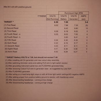 ------------- 1951 CA - 1944 C - 1949 B - Kubota M6800 |
Posted By: steve(ill)
Date Posted: 19 Jul 2024 at 10:03pm
|
found that after jumping Resistor to Positive Battery Ground (with headlamp ON) the reading is 5 AMPS and 8.11 volts.. IF you can verify that the "F" terminal wire to the BOX is not ground somewhere else, then YES... that is too much amps and volts for the resistor circuit.. If you take the JUMPER off the resistor, then the amps drop to ZERO because there is NO GROUND CIRCUIT.. Right ? There are aftermarket switchs, but some do not FIT in the box very well.. You can have your switch Professional REBUILT by Steve @ B&B if your interested... 1 . This tractor had no "ignition switch" from the factory. If you have one, then yes, the power can run thru the switch before going to the light switch. 2. The PRINT gives the impression that there are several ground wires. There are not.. The STARTER is grounded thru the case to the FRAME... the Generator is grounded thru the case to the Engine / frame.... the light switch is ground thru its case to the BOX... the BOX is grounded to the tractor FRAME thru the mounting bolts... NO WIRES except the GROUND on the battery.. the ENGINE / FRAME is the GROUND CIRCUIT. 3. No, the generator "F" terminal is not grounded with a wire at the generator. The WIRE goes to the light switch and is GROUNDED when the lights are on and runs thru the RESISTOR to GROUND when the lights are off.. It would appear you still have several problems with the light switch / box / wires.. I would verify that you have NO AMP CHARGE when you pull the ground off the RESISTOR and then 5 amps when you GROUND THE RESISTOR... If that is the case, then your generator needs Repaired or Adjusted ( brush) inside... ------------- Like them all, but love the "B"s. |
Posted By: steve(ill)
Date Posted: 19 Jul 2024 at 10:23pm
|
Dale, you need to temporarily forget about the light switch. It is just complicating the problem.. All you need in the LIGHT BOX , the RESISTOR , the WIRE FROM "F" and a good ground.... When you run the wire to the resistor , you get 3 amps.. when you run straight to ground you get 8 amps.. That will verify your generator is working correctly.. Dont care what the lights are doing.. worry about that later............. this is a simple version.... i might be temped to take the POWER wire off the light switch for now, just to verify that it is not adding to the problem. What if your "F" wire is ALWAYS GROUNDED at the switch due to wrong terminal or bad switch ????? 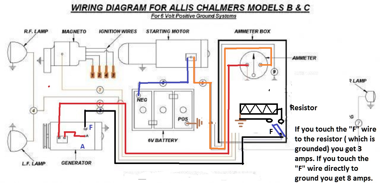 ------------- Like them all, but love the "B"s. |
Posted By: steve(ill)
Date Posted: 19 Jul 2024 at 10:30pm
|
It looks like on test 6-7-9 that you are getting 5 amps when you ground the resistor and put the "F" wire to the other side of the resistor.... ( dont care what the light is doing or what happens at low idle).... Now take the F wire and GROUND it to the battery.. You get 8 amps ??? or ? ------------- Like them all, but love the "B"s. |
Posted By: Dale (Stonelick)
Date Posted: 22 Jul 2024 at 7:22pm
|
After running through some more testing (FLASHED after each wiring change), at a point where I can live with the current results of about 4 AMPS in all three light switch positions (without headlamps). To fix all the problems, think I would need a replacement light switch and/or an adjustment to the genny’s 3rd brush. These tests were made with the front cover of the Instrument Panel Box removed. I had to separately ground the box to positive battery ground to get any AMP readings. The Instrument Panel Box is full - it contains: ammeter, starter solenoid button, ignition switch, and light switch. When testing with headlamp wired, only one of the bulbs worked (one appears to be burnt out). I used the light to test for amperage discharge - but none was noted. Light remained ON for all tests, under all 3 LS charging positions, both when key is ON and when engine is running (thinking LS is bad).
I appreciate all the helpful comments and suggestions, especially the one pointing out the need for a switch in the ammeter wire terminals. ------------- 1951 CA - 1944 C - 1949 B - Kubota M6800 |
Posted By: steve(ill)
Date Posted: 22 Jul 2024 at 7:33pm
|
a few days ago you had 8 amps... not sure how you got to 4 today ?... If you take the "F" terminal wire and go to the resistor, you get 4 amps... if you ground the "F" wire you still get 4 amps ? ....... That means your wire is always grounded somewhere.. you should have a LOWER reading when going thru the resistor... I think your wire from "F" might be touching ground somewhere... and your switch is definitely bad. ------------- Like them all, but love the "B"s. |
Posted By: Les Kerf
Date Posted: 22 Jul 2024 at 11:58pm
Was this with engine running? If the engine is not running with the light on and there is no discharge indicated on the ammeter, then it is either wired incorrectly or the ammeter is faulty. If the engine is running at high idle with a light on then a properly functioning system will not show a discharge because the generator will carry the load. It may show a charge occurring, depending on how many lights are burning. I am not convinced that your wiring is correct.
|
Posted By: Phil48ACWC
Date Posted: 23 Jul 2024 at 5:59am
| In 1999 I completely converted my WC to 12V with a Delco 10SI alternator with internal solid state regulator. The original 6V starter works just fine with 12V. Best thing I ever did to the electrical system. Never had any problems in 25 years and this tractor is used year round. All I had to do was adjust the belt tension. Just do it and don't look back. In the long run it will save you time, money, and aggravation. Especially aggravation. |
Posted By: jaybmiller
Date Posted: 23 Jul 2024 at 6:15am
|
FWIW IF you're into 'restoring' the tractor to original, then get a 2 wire genny and a cutout relay. Be sure to monitor acid level in 6 v battery, use 'fat cables, and keep everything clean. Cutout relay can be a diode in the OEM relay shell. If you want a super reliable tractor, upgrade to 12 volt alternator/battery system. Cheap battery, can upgrade lights to LEDs, EASY to jump start car from tractor,can add a winch, etc. If you use the CS130 series or baby Denso ,they fit/look 'better'. ------------- 3 D-14s,A-C forklift, B-112 Kubota BX23S lil' TOOT( The Other Orange Tractor) Never burn your bridges, unless you can walk on water |
Posted By: Dale (Stonelick)
Date Posted: 23 Jul 2024 at 1:54pm
|
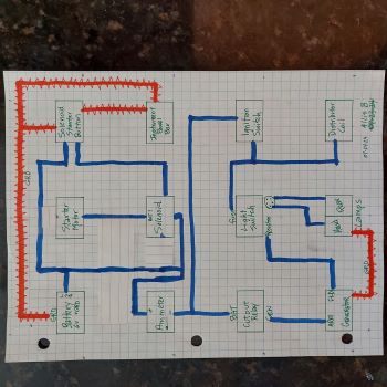
Steve: I had an earlier 10 AMP reading. Better grounding of the instrument panel and another generator FLASH seemed to be the only thing I did to bring it down to 4-5 AMPS. I do have a problem with inconsistent AMP readings - maybe it is a grounding problem? I installed (earlier) a new 16 gauge wire from FLD to resistor (the prior 12 volt regulator didn’t have one). I’ll test it with a 14 gauge wire to see if it makes a difference. Les Kerf: Lights are ON both when ignition switch is ON (engine not running) and when engine is running - on all three light switch positions. Thanks for noting that the ammeter should show no discharge with lights ON and engine running. My problem is I get the same 4 AMP reading both when the lights are wired and when they are not wired. Although the Ammeter reads HOT on both terminals, maybe it is bad. I’m pretty sure the light switch has a problem. I diagramed my wiring as best I could - see picture below. I can’t see any variance when compared to the published diagrams(??). Phil48 and jaybmiller: I’ve got too much invested in the 6 volt system to change it now. Steve B. helped me convert my Allis CA to 12 volt - I agree that it’s been trouble free. 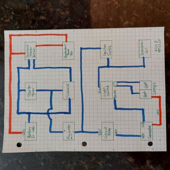 ------------- 1951 CA - 1944 C - 1949 B - Kubota M6800 |
Posted By: steve(ill)
Date Posted: 23 Jul 2024 at 4:00pm
|
If your amp guage is good, then 4 amps is reasonable. Why you can get 4 amps WITH and WITHOUT the resistor is questionable. Your light switch is no good, and wireing might also be questionable... You can follow the drawing, and still have a shorted wire on the switch terminals, or sharp edge of box, etc.
------------- Like them all, but love the "B"s. |
Posted By: Les Kerf
Date Posted: 24 Jul 2024 at 1:37am
I asked previously if the ammeter shows discharge when the lights are on with engine NOT running but you did not answer directly. The reason for asking is to determine if the ammeter is functioning with anywhere near reasonable accuracy. We aren't expecting ultra precision, just ballpark. With engine off, lights on, and ignition switch on, you should see maybe 4 amps to even 8-10 amps discharge. You may need to bump the engine a bit to get the points closed for this reading. Please do this test and let us know what you find. I look for the discharge-charge-oil pressure indication every time I start my tractor, it's just an automatic reflex; the needle should go down, then it should go up.
The lower half of your diagram looks ok but the upper half is just weird. Ammeter + should not go between the solenoid and starter. Battery hot, ammeter, and starter button hot can all go to the solenoid hot (big terminal). Starter button control goes to solenoid small terminal. The other solenoid big terminal goes to the starter. Erase that weird short blue line at the top of the starter and move the ammeter to the hot side of the solenoid. |
Posted By: steve(ill)
Date Posted: 24 Jul 2024 at 8:28am
back a ways i posted a color version of the wire diagram.. maybe the Original drawing would help...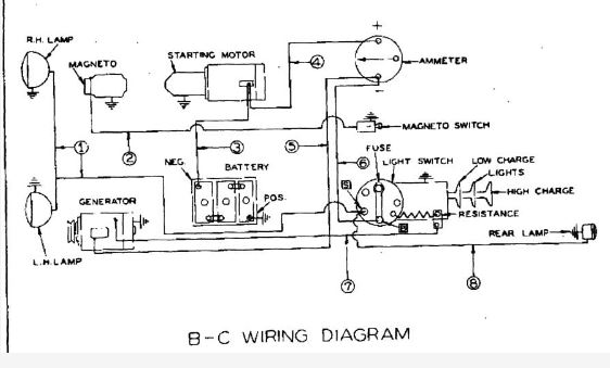 ------------- Like them all, but love the "B"s. |
Posted By: Dale (Stonelick)
Date Posted: 24 Jul 2024 at 2:41pm
|
Steve: I ran 12 gauge wire from FLD to Resistor - no change. I’ll keep looking for possible grounding issues. Do you have a wiring diagram that includes a starter solenoid and start button? Les Kerf:
My current plan is to live with what I got - 4/4/4 AMPS - and keep searching for possible ground issues. I’m in a better place now than before, thanks to everyone’s help. I’ll try a NOS light switch if I can find one. I doubt that the new style larger light switch will fit in my cluttered instrument panel box. ------------- 1951 CA - 1944 C - 1949 B - Kubota M6800 |
Posted By: Dale (Stonelick)
Date Posted: 24 Jul 2024 at 2:52pm
------------- 1951 CA - 1944 C - 1949 B - Kubota M6800 |
Posted By: Les Kerf
Date Posted: 24 Jul 2024 at 6:26pm
|
Posted By: Alberta Phil
Date Posted: 24 Jul 2024 at 7:05pm
|
Steve at B&B can rebuild your original light switch if you still have it. If not he may have some rebuilt ones in stock. He's done a few for me for my fleet and they all came back like new! |
Posted By: Dale (Stonelick)
Date Posted: 25 Jul 2024 at 8:35am
|
The light came ON under both tests - alternating ammeter polarities (which I took to mean switching jumper wires on ammeter terminals) - with all other wires disconnected. What do you conclude with regard to the ammeter? Not sure exactly what you meant by "in series". I just ran a jumper from Battery to ammeter terminal, and another jumper from Light to other ammeter terminal. Thanks for your help. ------------- 1951 CA - 1944 C - 1949 B - Kubota M6800 |
Posted By: Les Kerf
Date Posted: 25 Jul 2024 at 3:48pm
Ummm... nothing. I should have mentioned that the purpose of the test is to see what the ammeter actually reads in both directions. It should read something like 3-4 amps discharge one way and 3-4 amps charge the other way. If it doesn't read the same amount both ways then the gauge is faulty
Series means all of the current flows through one device and then through the next.
|
Posted By: Dale (Stonelick)
Date Posted: 25 Jul 2024 at 5:44pm
|
It reads +2 amp and -2 amp the other way. So the ammeter appears to be good? If I run same test, but with the light switch between the ammeter and light, suppose it would show that the light stays on using each of the 3 light switch positions. Something I already know. Maybe I can find a new switch with a resistor that fits my instrument box at one of the upcoming tractor shows in my area. ------------- 1951 CA - 1944 C - 1949 B - Kubota M6800 |
Posted By: Les Kerf
Date Posted: 25 Jul 2024 at 6:47pm
Ok, now we are getting somewhere.  That gives us confidence that the ammeter can be trusted. Now, let's try another experiment. You have proven that the light draws about 2 amps; let's use it instead of the resistor to control the generator field in an effort to prove the actual output of the generator. This should let you know if you really need to do any more work on the generator. Leave the light switch completely disconnected. Connect the ammeter directly to the output of the cutout relay, then directly to the battery. Connect one side of the light to the field terminal on the generator, connect the other side to ground. Use a jumper wire to energize the ignition (unless it's a magneto). It is important to NOT use any of the original wiring in case there are problems such as shorting, poor connections, etc. This is intended to test the generator itself. Run the engine at high idle, the light should be lit. Note the Volts and Amps. At high idle, short the field terminal to ground, the light should go out. Note the Volts and Amps (they should both increase). Vary the engine speed down to idle and see what happens ( the Volts and Amps should decrease, at some point the cutout should open and Amps should go to zero). |
Posted By: Dale (Stonelick)
Date Posted: 25 Jul 2024 at 9:10pm
|
Les - before I try to run test, wanted to make sure the wiring is okay in the picture below: 1. Red jumper wires are those you suggested 2. I added two squiggly dark green jumper wires: from Cutout/GEN to Genny/ARM, and from Ignition Switch to Distributor/Coil. Are these correct for this test? 3. I kept the GRD wire from Battery to Instrument Panel 4. To spin the Starter Motor to start engine, I can FLASH it from the Battery until it starts Let me know if this seems correct to you, or if something needs to change. 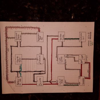 ------------- 1951 CA - 1944 C - 1949 B - Kubota M6800 |
Posted By: Les Kerf
Date Posted: 26 Jul 2024 at 9:31am
Hmmm... The intent of this test is to simulate taking the generator to a shop and having it checked out on a test stand. Since I do not own a test stand, I just use the tractor (or vehicle) as it already has a generator mount and a means of spinning the unit under test. The important thing to remember is that if you were to actually take the generator to a shop, they wouldn't have any of the wiring, etc. that is on your tractor that may interfere with the test. In order to accurately test/troubleshoot something, it is necessary to eliminate as many things as possible that may interfere with the test. Visualize how a shop would set up the generator for testing; they would have a mount, a means to spin it, a battery, an ammeter, and a voltmeter. They would also need a way to energize and control the field. And nothing else.
You do need this.
I would leave the ignition switch completely out of the circuit
I would use a dedicated jumper wire directly to the battery
This won't hurt anything, it is irrelevant to this test because everything is being bypassed.
Yup. Of course the battery needs to be grounded and also connected to the starter/solenoid I realize this seems like a lot of fiddling around (it is) but once it is all set up it's sorta fun to play with the field and observe how the outputs change. You will be manually simulating the action of a voltage regulator, albeit much slower and with less precision. Have fun! |
Posted By: Dale (Stonelick)
Date Posted: 26 Jul 2024 at 5:38pm
|
Got it wired for the test - not sure how. See wiring picture. BLUE wire: used same existing wiring (too many wires for me to jump). RED wire: new Jumper wires. “X” out faded: disconnected previous wiring.
What Is the conclusion: is Generator and wiring working properly? 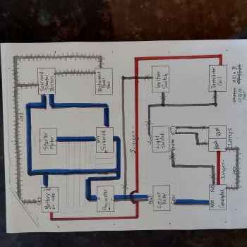 ------------- 1951 CA - 1944 C - 1949 B - Kubota M6800 |
Posted By: Les Kerf
Date Posted: 26 Jul 2024 at 6:36pm
Looks to me like you have a good, strong generator. If it were mine, I would put an "A" circuit voltage regulator on it (actually, I would build my own regulator, but let's not go there just yet). Now, you just need to decide what to do about your faulty light switch. |
Posted By: Les Kerf
Date Posted: 26 Jul 2024 at 10:12pm
Looks like you already own the solution
|
Posted By: jaybmiller
Date Posted: 27 Jul 2024 at 6:24am
|
replace the 6 decade old switch.. for fun, replace the open wire wound resistor with an enclosed one for real fun, replace mechanical guts of regulator with 'solid state devices' though what you have works fine according to the numbers. ------------- 3 D-14s,A-C forklift, B-112 Kubota BX23S lil' TOOT( The Other Orange Tractor) Never burn your bridges, unless you can walk on water |
Posted By: Dale (Stonelick)
Date Posted: 27 Jul 2024 at 11:10am
|
Thank you Les. And thanks to everyone else for your helpful comments and suggestions. A quick recap of problems, missteps, corrections and solutions: (1) originally had no amp reading unless a jump around voltage regulator, (2) multiple wiring problems, (3) replaced generator [with a used generator], (4) replaced voltage regulator with a cutout relay, (5) in retrospect, it seems that the tractor might have been wired as a 12 volt system, (6) the need for a good ground to the instrument panel box, (7) remembering to FLASH from BAT to GEN terminal after each modification, (8) positive test results on Generator, Ammeter and wiring, (9) now getting 4 amps at high idle under all three light switch positions, and (10) conclusion that the Light Switch needs to be replaced. One thing I should have done early on, is to install a battery disconnect switch. Thanks again. ------------- 1951 CA - 1944 C - 1949 B - Kubota M6800 |
Posted By: Les Kerf
Date Posted: 27 Jul 2024 at 12:33pm
And thank you for your feedback and diligent testing. So often we never get to know the results
|