| Author |
 Topic Search Topic Search  Topic Options Topic Options
|
Farrell(Utah) 
Orange Level

Joined: 11 Sep 2009
Location: Springville, Ut
Points: 517
|
 Post Options Post Options
") Thanks(0) Thanks(0)
") Quote Quote  Reply Reply
 Topic: WD45 diesel wiring diagram question Topic: WD45 diesel wiring diagram question
Posted: 01 Sep 2023 at 10:43pm |
I was looking at the wiring on my WD45 diesel and have a question about the L terminal on the voltage regulator. The tractor has a 12 volt generator with a four terminal voltage regulator. Currently, the L terrminal on the voltage regulator is connected to the light switch terminal in the instrument panel. It appears to be providing power for the lights. Where should the L terminal on my voltage regulator be connected in the instrument panel? Thanks.
|
|
A(1937), 2 G, 2 WD45 diesels, 6 WD45 gas, UC, 2 WD, D17 gas, WF, Farmall 400, D12, Kubota B3030
|
 |
|
Sponsored Links
|
|
|
steve(ill)
Orange Level Access
Joined: 11 Sep 2009
Location: illinois
Points: 81384
|
Post Options
Thanks(0)
Quote Reply
Posted: 02 Sep 2023 at 8:42am |
that should be correct... The "L" is just another HOT WIRE... It was a common terminal 50 years ago on some systems... normally it came from the ignition switch ... which fed the lights switch.
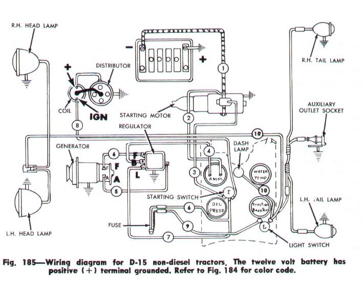
Here is a SIMILAR drawing... to give you an idea
Edited by steve(ill) - 02 Sep 2023 at 8:49am
|
|
Like them all, but love the "B"s.
|
|
steve(ill)
Orange Level Access
Joined: 11 Sep 2009
Location: illinois
Points: 81384
|
Post Options
Thanks(1)
Quote Reply
Posted: 02 Sep 2023 at 8:51am |
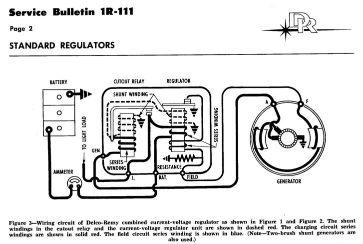
As shown in Figure 3, the regulator has an extra terminal marked "L" which is connected with the lower contact point in the cutout relay. This extra terminal permits current from the generator to be diverted to the load ( head lights) without its passing through the current-voltage regulator.
Edited by steve(ill) - 02 Sep 2023 at 8:52am
|
|
Like them all, but love the "B"s.
|
|
Les Kerf
Orange Level
Joined: 08 May 2020
Location: Idaho
Points: 792
|
Post Options
Thanks(0)
Quote Reply
Posted: 02 Sep 2023 at 10:00pm |
") steve(ill) wrote: steve(ill) wrote:
As shown in Figure 3, the regulator has an extra terminal marked "L" which is connected with the lower contact point in the cutout relay. This extra terminal permits current from the generator to be diverted to the load ( head lights) without its passing through the current-voltage regulator.
|
Thanks Steve, I never have seen that before. It also bypasses the ammeter.
|
|
ciero2003
Bronze Level

Joined: 25 Sep 2023
Location: Michigan
Points: 2
|
Post Options
Thanks(0)
Quote Reply
Posted: 25 Sep 2023 at 9:06am |
|
I have a '51 WD with a 12V generator. Could I use this diagram in wiring a WD properly?
|
|
steve(ill)
Orange Level Access
Joined: 11 Sep 2009
Location: illinois
Points: 81384
|
Post Options
Thanks(0)
Quote Reply
Posted: 25 Sep 2023 at 9:18am |
yes.... also determine if you want positive or negative ground.... but all the WIRES are the same.
if your regulator has an L terminal, you can run it to the light switch... If it does NOT have an L... just forget that part.
Edited by steve(ill) - 25 Sep 2023 at 9:21am
|
|
Like them all, but love the "B"s.
|
|
ciero2003
Bronze Level
Joined: 25 Sep 2023
Location: Michigan
Points: 2
|
Post Options
Thanks(0)
Quote Reply
Posted: 25 Sep 2023 at 9:22am |
|
Thanks so much!
|
|
steve(ill)
Orange Level Access
Joined: 11 Sep 2009
Location: illinois
Points: 81384
|
Post Options
Thanks(0)
Quote Reply
Posted: 25 Sep 2023 at 9:26am |
from the above DELCO link...
|
|
Like them all, but love the "B"s.
|
|