WD45 diesel wiring diagram question
Printed From: Unofficial Allis
Category: Allis Chalmers
Forum Name: Farm Equipment
Forum Description: everything about Allis-Chalmers farm equipment
URL: https://www.allischalmers.com/forum/forum_posts.asp?TID=196972
Printed Date: 13 Oct 2025 at 4:22pm
Software Version: Web Wiz Forums 11.10 - http://www.webwizforums.com
Topic: WD45 diesel wiring diagram question
Posted By: Farrell(Utah)
Subject: WD45 diesel wiring diagram question
Date Posted: 01 Sep 2023 at 10:43pm
|
I was looking at the wiring on my WD45 diesel and have a question about the L terminal on the voltage regulator. The tractor has a 12 volt generator with a four terminal voltage regulator. Currently, the L terrminal on the voltage regulator is connected to the light switch terminal in the instrument panel. It appears to be providing power for the lights. Where should the L terminal on my voltage regulator be connected in the instrument panel? Thanks. ------------- A(1937), 2 G, 2 WD45 diesels, 6 WD45 gas, UC, 2 WD, D17 gas, WF, Farmall 400, D12, Kubota B3030 |
Replies:
Posted By: steve(ill)
Date Posted: 02 Sep 2023 at 8:42am
|
that should be correct... The "L" is just another HOT WIRE... It was a common terminal 50 years ago on some systems... normally it came from the ignition switch ... which fed the lights switch. Here is a SIMILAR drawing... to give you an idea 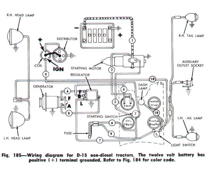 ------------- Like them all, but love the "B"s. |
Posted By: steve(ill)
Date Posted: 02 Sep 2023 at 8:51am
|
As shown in Figure 3, the regulator has an extra terminal marked "L" which is connected with the lower contact point in the cutout relay. This extra terminal permits current from the generator to be diverted to the load ( head lights) without its passing through the current-voltage regulator. https://regitar.com/image/file_downloads/Mechanical-Regulator-Service-Bulletin.pdf" rel="nofollow - |
Posted By: Les Kerf
Date Posted: 02 Sep 2023 at 10:00pm
Posted By: ciero2003 Date Posted: 25 Sep 2023 at 9:06am
Posted By: steve(ill) Date Posted: 25 Sep 2023 at 9:18am
Posted By: ciero2003 Date Posted: 25 Sep 2023 at 9:22am
Posted By: steve(ill) Date Posted: 25 Sep 2023 at 9:26am
|
") steve(ill) wrote:
steve(ill) wrote: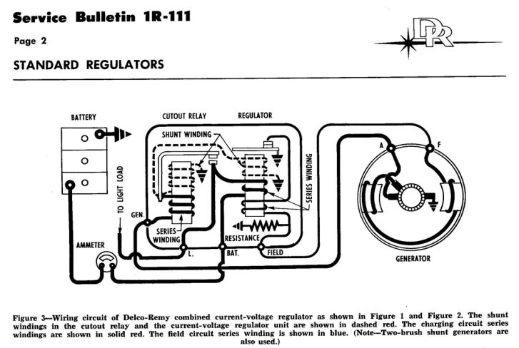
| Print Page | Close Window
Forum Software by Web Wiz Forums® version 11.10 - http://www.webwizforums.com Copyright ©2001-2017 Web Wiz Ltd. - https://www.webwiz.net |