| Author |
 Topic Search Topic Search  Topic Options Topic Options
|
dfwallis 
Orange Level

Joined: 09 Mar 2023
Location: DFW
Points: 948
|
 Post Options Post Options
") Thanks(0) Thanks(0)
 Quote Quote  Reply Reply
 Topic: CA Hold CAM Plate Orientation Topic: CA Hold CAM Plate Orientation
Posted: 16 Sep 2024 at 2:56pm |
|
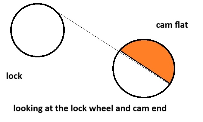
The hold valve plate (and bearing) was rusted fast to the control lever plate. I finally managed to separate them without doing damage with one exception. The press fit hold plate separated from the CAM (cleanly, it might be pressed back on and wedged back in place). I attempted to mark the orientation of the plate detent relative to the CAM lobe depression, but since I was attempting to rotate the two parts to loosen them up, I'm unsure if that was the correct position or not. The plunger that the CAM depresses is in the front (90 degree) position looking from the right side into the hole. If I align the plate in that orientation, that would mean that in the detent position, the plunger is NOT depressed. I think that means "hold", but could be reverse logic. Additionally, if detent hole is perfectly aligned in the center of the CAM lobe depression, since the detent ball is at about 135 degrees, the plunger would be in a "partial" depressed state (not exactly in the center of the lobe depression). Anyone know the correct orientation of the CAM detent relative to the CAM lobe depression? Thanks
|
|
1952 CA13092, CA Pickup Plow, CA Cultivator, CA Two Row Planter, Dunham-Lehr GC78 Disc, Grader Blade, 3pt Fm180 Finish Mower
|
 |
|
Sponsored Links
|
|
|
steve(ill)
Orange Level Access
Joined: 11 Sep 2009
Location: illinois
Points: 90878
|
Post Options
Thanks(0)
Quote Reply
Posted: 16 Sep 2024 at 3:33pm |
Gary... here is the reference drawing from yesterday.. Hopefully someone knows where the detent sets... Sorry, but i dont have a CA to look at.
|
|
Like them all, but love the "B"s.
|
|
dfwallis
Orange Level
Joined: 09 Mar 2023
Location: DFW
Points: 948
|
Post Options
Thanks(0)
Quote Reply
Posted: 16 Sep 2024 at 4:08pm |
|
Thanks, yup I have that in the manual but can't see the cam itself clearly enough
|
|
1952 CA13092, CA Pickup Plow, CA Cultivator, CA Two Row Planter, Dunham-Lehr GC78 Disc, Grader Blade, 3pt Fm180 Finish Mower
|
|
steve(ill)
Orange Level Access
Joined: 11 Sep 2009
Location: illinois
Points: 90878
|
Post Options
Thanks(0)
Quote Reply
Posted: 16 Sep 2024 at 4:21pm |
your talking about welding the SHAFT #35 to the PLATE #33.. seems like if it is OFF a little bit, then you rotate #35 plate to "match up" and work correctly... Dont have to be perfect, but yea, you dont want to be off 45 degrees...
Can you hold the SHAFT about the position that it needs to be, then hold plate #33 "about" where it needs to be.... and that will show your "about" where the plate #34 needs to set ? .... If someone had a good photo or directions that would be great... without that, im thinking a little MOCKUP TEST could get the job done.
by rereading your post.......... i think that is what your trying to do.... wish i could be more help !
Edited by steve(ill) - 16 Sep 2024 at 10:27pm
|
|
Like them all, but love the "B"s.
|
|
dfwallis
Orange Level
Joined: 09 Mar 2023
Location: DFW
Points: 948
|
Post Options
Thanks(0)
Quote Reply
Posted: 16 Sep 2024 at 4:46pm |
|
Yes, number 35. The problem is entirely within #35. With that orientation correct, the orientation with other parts is determined.
Edited by dfwallis - 16 Sep 2024 at 5:42pm
|
|
1952 CA13092, CA Pickup Plow, CA Cultivator, CA Two Row Planter, Dunham-Lehr GC78 Disc, Grader Blade, 3pt Fm180 Finish Mower
|
|
dfwallis
Orange Level
Joined: 09 Mar 2023
Location: DFW
Points: 948
|
Post Options
Thanks(0)
Quote Reply
Posted: 16 Sep 2024 at 6:29pm |
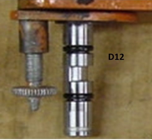
This image includes a side view of the CAM:
It appears that the low spot in the CAM is pretty much directly opposite the lock screw position. I'm not quite certain though that I can fully view the proper perspective in the image.
It really is a pain in the rear having 0 bars cell service. I have to walk a half mile down the road where the signal bounces off a large hill if I stand in about a 20 foot circle facing the hill :(
|
|
1952 CA13092, CA Pickup Plow, CA Cultivator, CA Two Row Planter, Dunham-Lehr GC78 Disc, Grader Blade, 3pt Fm180 Finish Mower
|
|
dfwallis
Orange Level
Joined: 09 Mar 2023
Location: DFW
Points: 948
|
Post Options
Thanks(0)
Quote Reply
Posted: 16 Sep 2024 at 6:35pm |
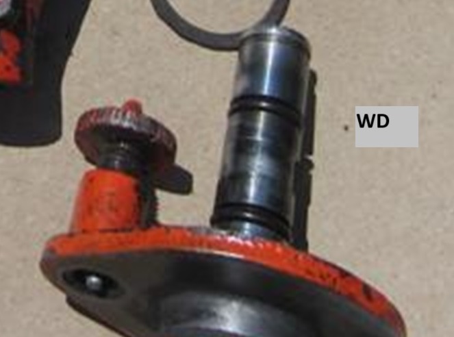
However, this WD image does not seem to show that:
|
|
1952 CA13092, CA Pickup Plow, CA Cultivator, CA Two Row Planter, Dunham-Lehr GC78 Disc, Grader Blade, 3pt Fm180 Finish Mower
|
|
dfwallis
Orange Level
Joined: 09 Mar 2023
Location: DFW
Points: 948
|
Post Options
Thanks(0)
Quote Reply
Posted: 16 Sep 2024 at 7:03pm |
|
After further review, aligning/matching per the CA and WD images seems to agree with my initial marking give or take a few degrees. Is there any reason for the CA and WD alignment to be different (the perspectives are still a little difficult to be 100% certain).
Edited by dfwallis - 16 Sep 2024 at 7:05pm
|
|
1952 CA13092, CA Pickup Plow, CA Cultivator, CA Two Row Planter, Dunham-Lehr GC78 Disc, Grader Blade, 3pt Fm180 Finish Mower
|
|
Gary
Orange Level Access
Joined: 13 Sep 2009
Location: Peterborough,On
Points: 5911
|
Post Options
Thanks(0)
Quote Reply
Posted: 16 Sep 2024 at 8:45pm |
|
|
|
steve(ill)
Orange Level Access
Joined: 11 Sep 2009
Location: illinois
Points: 90878
|
Post Options
Thanks(0)
Quote Reply
Posted: 16 Sep 2024 at 8:53pm |
Gary... i hope im not confusing you more, but i blew up the photos and they do look similar... like you said, the angles are deceiving and i could be wrong... it is deceiving bacause the WD photo is taken from the back side..
Edited by steve(ill) - 16 Sep 2024 at 9:03pm
|
|
Like them all, but love the "B"s.
|
|
dfwallis
Orange Level
Joined: 09 Mar 2023
Location: DFW
Points: 948
|
Post Options
Thanks(0)
Quote Reply
Posted: 16 Sep 2024 at 9:37pm |
I am thinking about buying one to experiment with mods if I see one cheap and in good shape, but this one seems in very good shape other than this hiccup...and the detent ball is toast
|
|
1952 CA13092, CA Pickup Plow, CA Cultivator, CA Two Row Planter, Dunham-Lehr GC78 Disc, Grader Blade, 3pt Fm180 Finish Mower
|
|
steve(ill)
Orange Level Access
Joined: 11 Sep 2009
Location: illinois
Points: 90878
|
Post Options
Thanks(0)
Quote Reply
Posted: 16 Sep 2024 at 10:29pm |
|
if you press the shaft into the plate and tack weld it... what is the WORST case that can happen ??? the lift lever on plate 33 is pointed off a little ??? maybe thats a big deal, maybe not ?
Edited by steve(ill) - 16 Sep 2024 at 10:29pm
|
|
Like them all, but love the "B"s.
|
|
dfwallis
Orange Level
Joined: 09 Mar 2023
Location: DFW
Points: 948
|
Post Options
Thanks(0)
Quote Reply
Posted: 17 Sep 2024 at 2:13am |
|
It presses onto a copper ring. I think a few hits with a punch and some locktite will be enough
|
|
1952 CA13092, CA Pickup Plow, CA Cultivator, CA Two Row Planter, Dunham-Lehr GC78 Disc, Grader Blade, 3pt Fm180 Finish Mower
|
|


 Gary wrote: