| Author |
 Topic Search Topic Search  Topic Options Topic Options
|
StanGreen 
Bronze Level

Joined: 13 Nov 2022
Location: US
Points: 60
|
 Post Options Post Options
") Thanks(0) Thanks(0)
 Quote Quote  Reply Reply
 Topic: Three Position Switch Topic: Three Position Switch
Posted: 28 Sep 2023 at 9:22am |
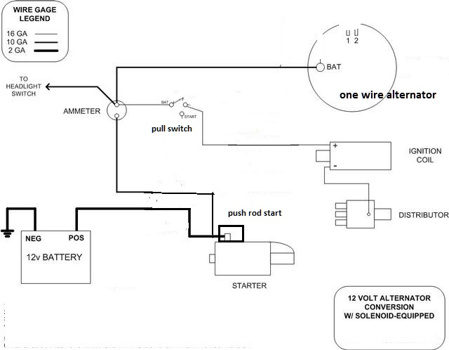
I am replacing all the wiring on my WD45. It had a broken three position switch so I bought a new one. (BTW: The switch was on connected in the tractor so I cannot use that for reference. No wonder the lights did not work.) The wiring kit I bought said it came with a wiring diagram, but it only comes with a parts list. The parts list does not mention the three position switch. I am trying to figure out how to wire the three position switch. I have test it and the off position (all the way in) and it works. The third position (all the way out) passes power between the input and the output (the two bottom connectors.) But I cannot figure out what position two (half way out) does. I would have thought that it would cut the voltage, but my testing shows no current flow in position two. What should position two do and how do I wire it? There is also a Generator Filed connector that I don't know what to connect to. Again, what does it do and how do I wire it.
Lastly, the fuse holder is not very tight. Has anyone seen the fuse fall out?
Here is what the switch looks like: 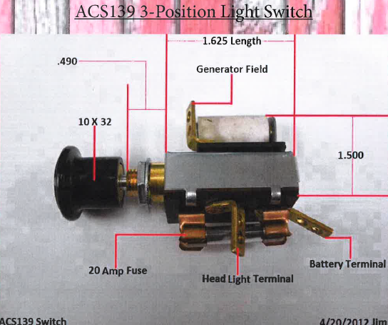 |
 |
|
Sponsored Links
|
|
|
JoeM(GA)
Orange Level

Joined: 12 Sep 2009
Location: Cumming,GA
Points: 4860
|
Post Options
Thanks(0)
Quote Reply
Posted: 28 Sep 2023 at 9:34am |
all the way in should give you about a 3 amp charge, first notch out should keep you still around 3 amps and headlights on. All the way out should get you 10-12 amps (careful here, easy to overcharge battery)
should only have the three terminals, power in for lights, power out for lights, and the field terminal which controls the charging rate. A slight squeeze on the fuse terminals with some pliers should tighten them up
all that being said, with the crap being imported today, you sometimes have to play with the switch when pulling it out to get it to do right, and I have one which the lights come on when the high charge position is chosen
|
|
Allis Express North Georgia
41 WC,48 UC Cane,7-G's,
Ford 345C TLB
|
|
StanGreen
Bronze Level
Joined: 13 Nov 2022
Location: US
Points: 60
|
Post Options
Thanks(0)
Quote Reply
Posted: 28 Sep 2023 at 12:33pm |
|
I am very confused here. How can the light switch have anything to do with the rate of charge for the battery? How would this even be wired? (BTW: I am using a single wire alternator.)
|
|
mdm1
Orange Level

Joined: 12 Sep 2009
Location: Onalaska, WI
Points: 2682
|
Post Options
Thanks(0)
Quote Reply
Posted: 28 Sep 2023 at 12:52pm |
The switch is for the 6v charging, factory original setup. You have apparently converted to 12v. Don't need that switch now. It worked like a voltage regulator. you could use the switch just for the lights if you wanted. Look up the wiring diagram for a 6-12v conversion for your tractor. Will show you how to wire it. Try this link, scroll down and there is a wiring diagram that should help you. https://www.allischalmers.com/forum/wd45-electrical-help-please_topic187028.html
|
|
Everything is impossible until someone does it! WD45-trip loader 1947 c w/woods belly mower, 1939 B, #3 sickle mower 1944 B, 2 1948 G's. Misc other equipment that my wife calls JUNK!
|
|
steve(ill)
Orange Level Access
Joined: 11 Sep 2009
Location: illinois
Points: 88656
|
Post Options
Thanks(0)
Quote Reply
Posted: 28 Sep 2023 at 12:56pm |
|
the TOP terminal says GENERATOR FIELD... that connects to the "F" terminal on the generator... That is the GROUND terminal for the Generator..... With the lights off, the "F" wire goes thru the resistor to ground ( 3 OHMS) and makes a LOW CHARGE.. With the lights ON the "F" wire is directly shorted to GROUND thru the switch (bypass the resistor), and causes the Generator to charge FULL --- 8 to 10 amps.
|
|
Like them all, but love the "B"s.
|
|
steve(ill)
Orange Level Access
Joined: 11 Sep 2009
Location: illinois
Points: 88656
|
Post Options
Thanks(0)
Quote Reply
Posted: 28 Sep 2023 at 12:59pm |
OOOPS... mdm1 is right... the 12v alternator does not need the resistor. You Could just use a toggle ON- OFF switch for the head lights. ...or .. You can use the 3 positions switch for looks.. just dont need the center position-- just ON- OFF..
Now the problem is, was your harness setup for the alternator 12v system or the old 6 v ?? ..you no longer have the "F" ground wire... the OLD "A" terminal wire on the generator runs to the ammeter ... thru to the battery..... That would be the BIG LUG on the back of the NEW Alternator.. .... are you using an ammeter or a Volt meter ??
Edited by steve(ill) - 28 Sep 2023 at 1:08pm
|
|
Like them all, but love the "B"s.
|
|
StanGreen
Bronze Level
Joined: 13 Nov 2022
Location: US
Points: 60
|
Post Options
Thanks(0)
Quote Reply
Posted: 28 Sep 2023 at 3:25pm |
|
Thanks. It was converted to 12V way before my time with it. It is interesting how they used the lights to decide the battery charge. Since the lights were the only major draw on the battery I can see why they did it. I will just have to live with on/off for the lights.
|
|
Ted J
Orange Level

Joined: 05 Jul 2010
Location: La Crosse, WI
Points: 18943
|
Post Options
Thanks(0)
Quote Reply
Posted: 28 Sep 2023 at 4:23pm |
|
That's the idea. When they are converted over to 12v that switch is taken out and replaced with just a simple on/off switch with an inline fuse to control the lights.
Edited by Ted J - 28 Sep 2023 at 4:24pm
|
|
"Allis-Express"
19?? WC / 1941 C / 1952 CA / 1956 WD45 / 1957 WD45 / 1958 D-17
|
|
StanGreen
Bronze Level
Joined: 13 Nov 2022
Location: US
Points: 60
|
Post Options
Thanks(0)
Quote Reply
Posted: 28 Sep 2023 at 10:00pm |
The people who did the conversion did a hack job. There was on part held together a bread tie. I am sure the lights were to complex for them, so they just disconnected them. I do not recall my Grandfather ever running the tractor after dark. I guess no headlights would do that. 
|
|