| Author |
 Topic Search Topic Search  Topic Options Topic Options
|
Auntwayne 
Orange Level

Joined: 23 Apr 2011
Location: Edwardsville Il
Points: 1589
|
 Post Options Post Options
") Thanks(0) Thanks(0)
 Quote Quote  Reply Reply
 Topic: WD 45 HYDRAULICS DROP Topic: WD 45 HYDRAULICS DROP
Posted: 12 May 2015 at 9:10pm |
|
We have two WDs that the hydraulics lift fine . How ever when lowering equipment ,if lowered at a regular slow speed , the implement will lower normal until at about the half way on the quadrant , the piece of equipment will slam to the ground . Since we know that is whats going to happen , we just finish lowering with the lever very slowly . One tractor's pump has never been rebuilt , and the other was done recently . I remember them both acting this way since I was a kid in the 60s . More shims ?
|
 |
|
Sponsored Links
|
|
|
DrAllis
Orange Level Access
Joined: 12 Sep 2009
Points: 22117
|
Post Options
Thanks(0)
Quote Reply
Posted: 12 May 2015 at 9:21pm |
|
Adjust the pump for "hold position".
|
|
Auntwayne
Orange Level
Joined: 23 Apr 2011
Location: Edwardsville Il
Points: 1589
|
Post Options
Thanks(0)
Quote Reply
Posted: 12 May 2015 at 9:41pm |
|
Thanks for the quick reply Dr. Will check them both out tomorrow and let you know .
Duane
|
|
SteveM C/IL
Orange Level Access
Joined: 12 Sep 2009
Location: Shelbyville IL
Points: 8667
|
Post Options
Thanks(0)
Quote Reply
Posted: 13 May 2015 at 12:05am |
|
The lift link and hold valve link need to be in harmony but sometimes the theoretical relationship isn't what works best. Just sayin....
|
|
DrAllis
Orange Level Access
Joined: 12 Sep 2009
Points: 22117
|
Post Options
Thanks(0)
Quote Reply
Posted: 13 May 2015 at 8:00am |
|
Yes, indeed. The linkage needs to be in "harmonious-synchronization". When adjusted correctly, I can't imagine any hydraulic system being more predictable on drop rate.
|
|
Auntwayne
Orange Level
Joined: 23 Apr 2011
Location: Edwardsville Il
Points: 1589
|
Post Options
Thanks(0)
Quote Reply
Posted: 13 May 2015 at 8:50pm |
|
OK , just got home from the farm , both WDs have the same exact set up , Turn screw "A" into body. Turn screw "B" out of body locking plates together. Turn screw "D" out as far as possible. And , screw "C" is out as far as possible as well . Now what ?
They have already been set up this way since we quit cultivating in the early 70s .
Edited by Auntwayne - 13 May 2015 at 8:53pm
|
|
MACK
Orange Level
Joined: 17 Nov 2009
Points: 7664
|
Post Options
Thanks(0)
Quote Reply
Posted: 13 May 2015 at 9:52pm |
|
It is the operator that controles the speed of drop. Pull the lever down until it droped the speed you want. Yes, if you pull the lever all the way down it will drop fast. If you want to control the speed of drop, put a adjustable one way check valve in line from one cylinder. MACK
|
|
Auntwayne
Orange Level
Joined: 23 Apr 2011
Location: Edwardsville Il
Points: 1589
|
Post Options
Thanks(0)
Quote Reply
Posted: 13 May 2015 at 10:04pm |
|
I can not lower the hydraulic lever any SLOWER , we are talking 5, 6, 7, 8 seconds from initial start to "DROP" .
We do" NOT " just drop the lever , we are so used to the slam to the ground that we might even use both hands to cautiously , gingerly lower the lever .
Edited by Auntwayne - 13 May 2015 at 10:14pm
|
|
Allis dave
Orange Level
Joined: 10 May 2012
Location: Northern IN
Points: 3073
|
Post Options
Thanks(0)
Quote Reply
Posted: 14 May 2015 at 7:45am |
|
More shim will only add pressure to the system, not adjust the drop. It sounds like you have the system in hold position. Right or wrong I usually keep mine in traction boost position. That most it work more like a standard 3-point, instead of a regular hydraulic lever with up-hold-down.
Sounds like maybe the lever finally releases from hold position then drops the equipment. For fun, I'd unscrew and separate the plates and see how that works.
|
|
Allis dave
Orange Level
Joined: 10 May 2012
Location: Northern IN
Points: 3073
|
Post Options
Thanks(0)
Quote Reply
Posted: 14 May 2015 at 7:53am |
|
I'm trying to remember which screw is which letter. You can leave screw 'A' (the bottom screw) turned into the control housing. This will ignore any bell housing spring movement and disable traction boost. Turn screw 'B' into body and unlock plated to make system act more like a 3-point. See what happens
|
|
Auntwayne
Orange Level
Joined: 23 Apr 2011
Location: Edwardsville Il
Points: 1589
|
Post Options
Thanks(0)
Quote Reply
Posted: 14 May 2015 at 9:50pm |
|
Allis Dave , You sir have hit the nail on the head with what exactly is happening with both tractors . When lowering the piece of equipment , they make a complete stop half way down , then the tractor rocks up and down ( counter balance ). Then you grab the hydraulic lever with both hands to continue more carefully controlling the rest of the lowering . I will let you know on Saturday how the adjustments work out .
|
|
Zimobog
Silver Level

Joined: 03 Aug 2014
Location: Alaska
Points: 54
|
Post Options
Thanks(0)
Quote Reply
Posted: 14 May 2015 at 10:25pm |
|
Hey guys this is great info- I'm replacing the upper assembly right now and was hoping to slide a question in here:
I took pretty good photos of this little project. Except how the spring and ball thing goes in. Could someone tell me what I forgot to photograph here? Thanks all and thanks Bill Deppe for the parts!
|
|
Allis dave
Orange Level
Joined: 10 May 2012
Location: Northern IN
Points: 3073
|
Post Options
Thanks(0)
Quote Reply
Posted: 15 May 2015 at 6:53am |
|
Zimobog,
I think the ball just drops in the center then the spring. Seems like the adjustment screw has a needle that goes through the spring center, but don't remember for sure.
Best money you can spend is to buy an operators manual and official Allis service manual from ebay. You can get copies for about $20. The operators manual gives all part breakdowns and the service manual gives details pump rebuild instructions.
|
|
Auntwayne
Orange Level
Joined: 23 Apr 2011
Location: Edwardsville Il
Points: 1589
|
Post Options
Thanks(0)
Quote Reply
Posted: 15 May 2015 at 8:18am |
|
Plunger-valve seat-valve ball-spring-seal-shim-adjusting screw .
|
|
Zimobog
Silver Level
Joined: 03 Aug 2014
Location: Alaska
Points: 54
|
Post Options
Thanks(0)
Quote Reply
Posted: 17 May 2015 at 1:30pm |
|
I've got the manual. Doesn't do to well in showing this one part. I'm thinking the spring up into the upper assembly and the ball rests on top of the lower with fluid pressure from the lower pushing it up.
I don't know the terminology and I usually internet off my phone, so I can't post photo too well.
|
|
Zimobog
Silver Level
Joined: 03 Aug 2014
Location: Alaska
Points: 54
|
Post Options
Thanks(0)
Quote Reply
Posted: 18 May 2015 at 3:45pm |
Ok, here's a photo of the part I'm talking about. What do you think? 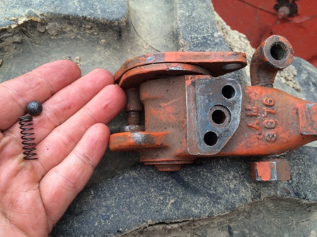
|
|
DrAllis
Orange Level Access
Joined: 12 Sep 2009
Points: 22117
|
Post Options
Thanks(0)
Quote Reply
Posted: 18 May 2015 at 4:24pm |
|
That looks to me like the "detent" ball and spring that locks the plates in the hold position.....maybe not.
|
|
Allis dave
Orange Level
Joined: 10 May 2012
Location: Northern IN
Points: 3073
|
Post Options
Thanks(0)
Quote Reply
Posted: 19 May 2015 at 9:54am |
|
I hope they're the detent ball and spring. They're pretty rusty looking to be the hold valve check valve
|
|
Zimobog
Silver Level
Joined: 03 Aug 2014
Location: Alaska
Points: 54
|
Post Options
Thanks(0)
Quote Reply
Posted: 19 May 2015 at 11:00am |
The detent ball and spring pass "horizontally" thru the upper assembly and end up against those plates, correct?
If so, this isn't it.
If it is the hold valve check valve, how does it sit between the upper and lower? Spring down or spring up?
The upper pump part pictured is from salvage and didn't come from my original unit and didn't come with this valve.
I was also curious if there was originally some sort of o-ring as well had isn't there now.
|
|
stu(ON)
Orange Level
Joined: 12 Sep 2009
Points: 377
|
Post Options
Thanks(0)
Quote Reply
Posted: 19 May 2015 at 12:52pm |
Not sure what you have for a manual. However, you can go to the AGCO Allis PartsBook site Or to this site and download the WD Parts Manual http://www.grandpastractor.com/kunena/allis-chalmers-tractors/435-wd45-parts-book.htmlAnd on page 282 of the last one, it shows part # 18 as being the seal between the valve components that you asked about. It also shows parts 15 & 16 looking a lot like the detent ball & spring as mentioned previously.
Edited by stu(ON) - 19 May 2015 at 8:31pm
|
|
Zimobog
Silver Level
Joined: 03 Aug 2014
Location: Alaska
Points: 54
|
Post Options
Thanks(0)
Quote Reply
Posted: 20 May 2015 at 8:24am |
stu(ON), Thanks very much! The link to the parts manual is one I needed. The shop manual's diagrams don't hold a candle to the parts manual's drawings.
I'm starting to think I just had that part in the wrong spot, but nice to know I am missing some o-rings as well.
I guess I will call an auto parts store and see if they can look up the o-ring size based on the part number.
|
|
Allis dave
Orange Level
Joined: 10 May 2012
Location: Northern IN
Points: 3073
|
Post Options
Thanks(0)
Quote Reply
Posted: 21 May 2015 at 9:59am |
|
If you go to about any general hardware store you can get a couple different o-ring sizes for about $.20 each and try them. You'll know if it's the wrong size.
|
|
Zimobog
Silver Level
Joined: 03 Aug 2014
Location: Alaska
Points: 54
|
Post Options
Thanks(0)
Quote Reply
Posted: 24 May 2015 at 2:43pm |
Guys thanks for the help and links to manuals.
Apparently, I am an idiot. That WAS just the indent ball and spring. I confirmed that by taking apart the old part. Last time I had reassembled it, I didn't put it back.
So I put the replacement on with the O ring in place and a gasket. Everything worked fine.
Thanks again.
|
|


