417 loader mounting help.
Printed From: Unofficial Allis
Category: Allis Chalmers
Forum Name: Farm Equipment
Forum Description: everything about Allis-Chalmers farm equipment
URL: https://www.allischalmers.com/forum/forum_posts.asp?TID=205054
Printed Date: 01 Apr 2026 at 9:12pm
Software Version: Web Wiz Forums 11.10 - http://www.webwizforums.com
Topic: 417 loader mounting help.
Posted By: JoshDay94
Subject: 417 loader mounting help.
Date Posted: 22 Jan 2025 at 8:26am
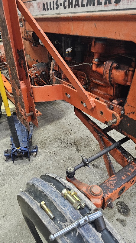
| Hello. Im mounting the 415/17 loader to my series 4, D17. The right hand bracket that goes to axle hits the traction control linkage and rubs the hydraulic cylinder. I have a hard time seeing how I could get the ubolt around axle too. Can someone please post a picture of how theirs is bolted on. Thank you |
Replies:
Posted By: JoshDay94
Date Posted: 22 Jan 2025 at 8:29am
|
Posted By: JoshDay94
Date Posted: 22 Jan 2025 at 8:31am
|
Posted By: 8070nc
Date Posted: 22 Jan 2025 at 9:19am
|
On a 500 series theres a 3/4 spacer between the engine frame rail and loader frame. They were left out when installed on the larger tractors. I dont know about a 400 series. ------------- 1984 80780 1957 D14 DES 300 with 25000 engine 616 tractor |
Posted By: DrAllis
Date Posted: 22 Jan 2025 at 9:22am
| Swap sides. U-bolt and angle iron are outside the fender mtg plate, not inside. |
Posted By: Gary
Date Posted: 22 Jan 2025 at 9:32am
|
Hi Josh I had a look in an Allis Parts Catalog for the 400 and 500 Series Loaders. The Rear Mounting Brackets for a D-15 are different from those for a D-17. For a D-15 the Angle Iron butts up against the front side of the Axle Housing. This Angle Iron tilts forward at about a 45' angle. For the D-17, the Angle Iron butts up to the rear side of the Axle Housing. This Angle is an extension of the Loader Frame itself, and is angled approx. 45' rearward' I am not familiar with any of that extra Set-up around the R/H Axle Housing that you show and refer to as part of the Traction Booster System. Gary |
Posted By: JoshDay94
Date Posted: 22 Jan 2025 at 10:02am
Dr. I swapped them out but they still won't clear the fender brackets. 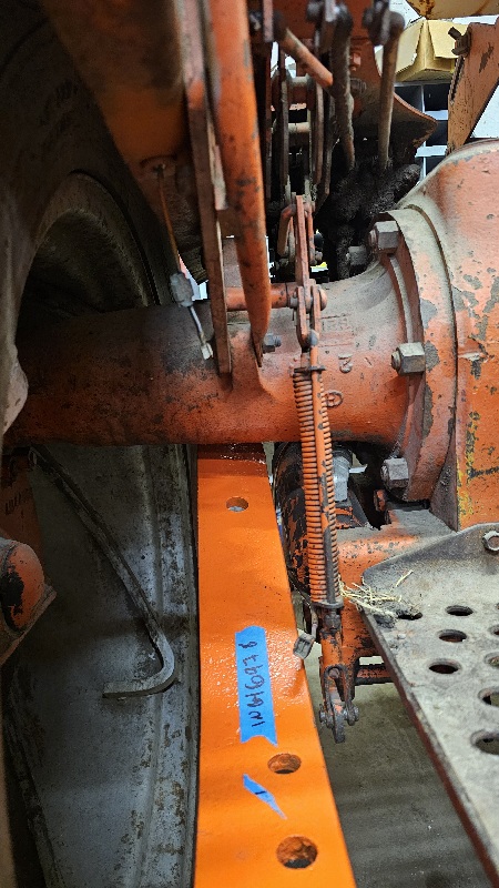
|
Posted By: JoshDay94
Date Posted: 22 Jan 2025 at 10:07am
| I have the 17 series brackets but it lines up with the mounting brackets for the fenders. |
Posted By: JoshDay94
Date Posted: 22 Jan 2025 at 10:08am
| Dr. Are the finder mounting points at different areas on the axle for the series 4 compared to series 1 thru 3? |
Posted By: DrAllis
Date Posted: 22 Jan 2025 at 10:12am
| Nope. The pre-series 4 doesn't have that TBoost linkage there, but I know the U-bolt goes on the outside of the fender bracket plate. You CANNOT run the rear wheels 100% clear in. They must be out at least 2 inches if not 4 inches. |
Posted By: JoshDay94
Date Posted: 22 Jan 2025 at 10:22am
Ok, i will move wheels out, but even then if i put bracket on the outside of fender the holes are off from bracket to loader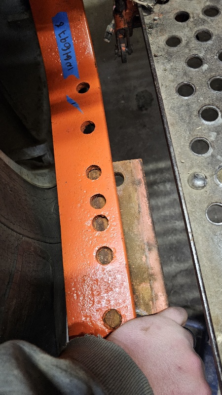
|
Posted By: JoshDay94
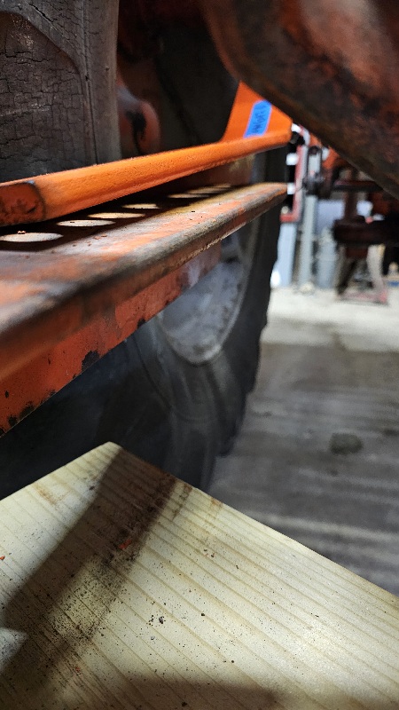
Date Posted: 22 Jan 2025 at 10:25am
| Also there is a gap between the angle and the axle like a 2 inch square tubing could fit between bracket and under/rear side of axle. |
Posted By: DrAllis
Date Posted: 22 Jan 2025 at 11:07am
| Leave the bolts loose on the tractor/loader side frames and pull the loader out to meet the holes. This isn't like a connecting rod cap inside an engine, precision machined. You have to use pry bars and lineup punches for assembly. |
Posted By: DrAllis
Date Posted: 22 Jan 2025 at 11:11am
| Someone else better get in here. I'm now wondering if there are 3/4" spacer plates between the side frames and the loader frame for a 400-series loader on a D-15-17. I know you don't use them on a 180 on up with a 500 series loader, but must use them on a 175 on down with a 500 series loader. |
Posted By: JoshDay94
Date Posted: 22 Jan 2025 at 11:24am
| The manual only speaks for spacers for the D14. Im trying to get it somewhat mounted to axle between stuff going on at work. I will get pictures more in a min. |
Posted By: JoshDay94
Date Posted: 22 Jan 2025 at 11:25am
| I just spent $1900 to rebuild all 4 cylinders so I'm pretty far in depth now for it not to work now 😅 |
Posted By: DrAllis
Date Posted: 22 Jan 2025 at 11:28am
| OK. If the D-14 needs them, the D-15-17 shouldn't. |
Posted By: JoshDay94
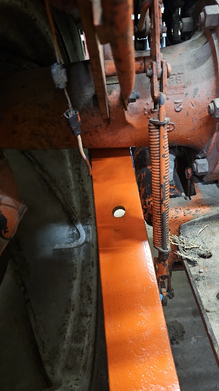
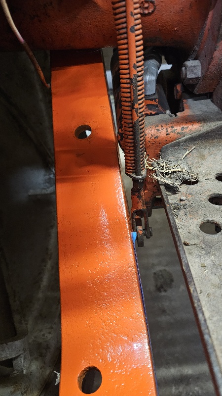
Date Posted: 22 Jan 2025 at 11:42am
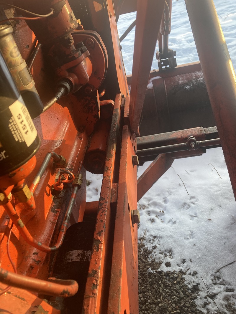
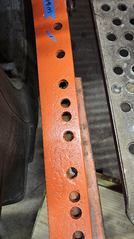  This is with ubolt snug to axle. But im out of threads and can't tighten anymore. They are agco part number for this loader. |
Posted By: 8070nc
Date Posted: 22 Jan 2025 at 12:06pm
|
Id measure between the uprights with the frames mounted to the front of the tractor. If that doesnt match the boom width you would know if you need spacers ------------- 1984 80780 1957 D14 DES 300 with 25000 engine 616 tractor |
Posted By: JoshDay94
Date Posted: 22 Jan 2025 at 12:12pm
| I think I found the issue. One of the angles are bent pretty good. I put the other side together and it lined up almost perfectly. I was having a heart attack after how much cash I have sunk into this. Will update soon |
Posted By: Gary
Date Posted: 22 Jan 2025 at 12:30pm
|
Josh and Dr. I had a look in the Allis Parts Catalog for the 400 and 500 Series Loaders. Confirmed that the D-14, D-15, and D-17 all use the same Side Frames and Boom. Josh has it right, the narrower D-14 requires the Spacers, 1 front and 2 rear, between the Side Frame and the Tractor Frame. Same for both sides. Then had a look in the Allis TM-328 Operating Instructions and Parts Illustrations 400 and 500 Series Loaders. On Page 10 is an unusual Picture. Fig. 7 is tagged as 417 R/H Rear Frame Mount - 'U' bolt is inside the Fender Fig. 9 is tagged as 517 R/H Rear Frame Mount - 'U' bolt is inside the Fender Wouldn't the 517 have to be on a Ser.IV with the Live Hydraulics, like Josh's? Gary |
Posted By: DrAllis
Date Posted: 22 Jan 2025 at 12:38pm
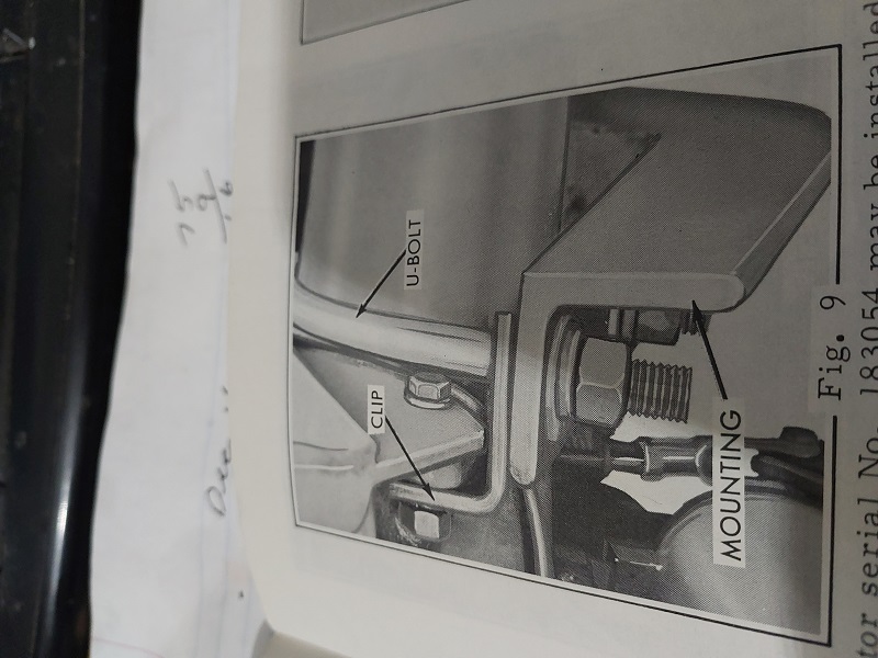
| Maybe I'm cornfusing a 500 axle connection with a 400 axle connection. When the U-bolt is outside the fender bracket, there is a small angle iron "clip" that slides on the U-bolt to keep it from working its way towards the rear wheel. If the U-bolt is truly inside the fender, this wouldn't be needed. If the U-bolt is indeed to be on the inside of the fender plate, the TBoost linkage may have to be removed ?? to make room. |
Posted By: JoshDay94
Date Posted: 22 Jan 2025 at 1:23pm
| It not only hits the linkage but also the 3point cylinders. So it has to go on the outside of the fenders. I was hoping for a 500 series loader but for $350 for this 417 I couldn't pass it up. |
Posted By: Kenny L.
Date Posted: 22 Jan 2025 at 2:36pm
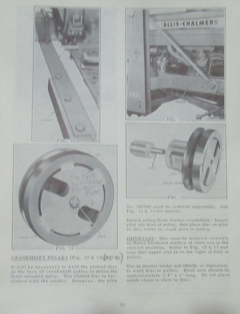
pic out of loader operating instructions (form tm-374)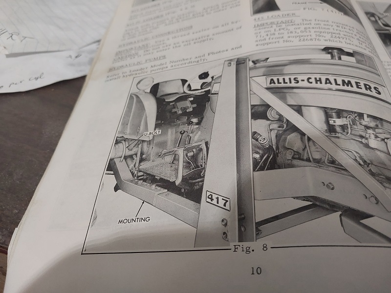 |
Posted By: Gary
Date Posted: 22 Jan 2025 at 2:50pm
|
Josh As I understand it, you actually got more being a 400 Series. The L/H Frame Mount of a 400 Series has the Hydraulic Oil contained inside the structure, along with the outlet at the bottom to feed the Front Mounted Pump, the return line fitting higher up, the Oil Fill Spout and Cap at the top. Also connections for the Bucket tilt and Boom Lift Valves. The 500 Series would not have any of this extra because of the Live Hydraulic along with a pair of Double Acting Hydraulic Control Valves as part of the Tractor. Still can't figure out why the Ser.IV has the Traction Booster Set-up like yours. Allis D Series Traction Booster System started in 1957 with the intro. of D-14 and D-17. It had to be modified to suit the introduced 3 pt hitch, but still the same working principle. Perhaps another Forum Member has a D-17 Ser.IV with a 400 or 500 Series Loader and could comment and / or provide pictures. Gary |
Posted By: Kenny L.
Date Posted: 22 Jan 2025 at 3:00pm
|
No spacer needed for a 417 loader, two things come to mind, one something is bent or it's badge wrong, I would guess it's bent or maybe the angle that the rear mount goes on has been broke and rewelded. I put a 415 on my D17-1 and had to rework the mounting brackets. When you run out of threads on the ubolt clamp put some more washer or something to be able to pull it down further and like Dr. said leave thing loose until you've every bolt installed. HTH. |
Posted By: Kenny L.
Date Posted: 22 Jan 2025 at 3:14pm
| Gary, the D-17 IV has live hyd and the other D series don't. |
Posted By: Gary
Date Posted: 22 Jan 2025 at 3:38pm
|
Hi Kenny Thanks for posting that picture. It is very similar to the one I was looking at. But it is different. If you look close you can see a bit of the 'Live' Hydraulic Pump hidden behind the Loader Frame Upright. Also it looks like you can see the Traction Booster Linkage mounted to the Axle Housing. That is the Picture Josh needs. Am I seeing correctly, the 'U bolt' is between the Fender and the Wheel, and the Traction Booster is by itself inside the Fender Bracket? Gary |
Posted By: DrAllis
Date Posted: 22 Jan 2025 at 3:48pm
| Traction Booster linkage and the lift arm cylinders are unique to the D-17 IV, One-Seventy and 175 tractors. |
Posted By: Brian G. NY
Date Posted: 22 Jan 2025 at 4:12pm
  Here are some pictures from the owner's manual that may (or may not) help. Here are some pictures from the owner's manual that may (or may not) help.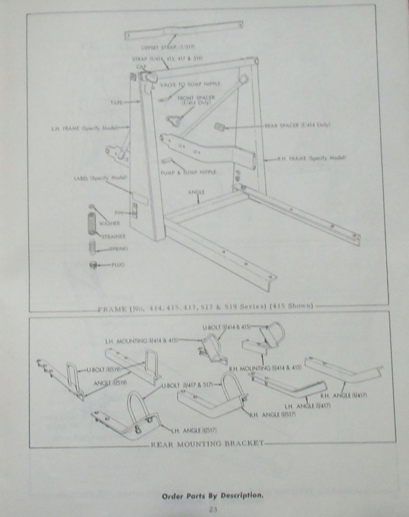 |
Posted By: JoshDay94
Date Posted: 22 Jan 2025 at 4:29pm
|
Kenny this is exactly the picture I needed My manual doesn't have that! Does it also show how the angle clips from u bolt to finder brackets that Dr. Talked about? |
Posted By: JoshDay94
Date Posted: 22 Jan 2025 at 4:31pm
This is same manual I have the one Kenny posted must be from a different one. |
 Brian G. NY wrote:
Posted By: JoshDay94
Date Posted: 22 Jan 2025 at 4:32pm
|
Posted By: Gary
Date Posted: 22 Jan 2025 at 5:20pm
|
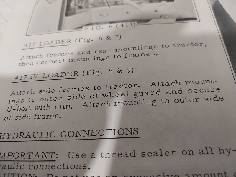
Josh Looking at Kenny's P. 10 Fig. 8 Picture, the R/H Loader Frame is outside the Fender Bracket, and you probably need to Power out the Power Shift Wheel to provide clearance for the Loader Frame. As someone mentioned earlier, you'll need to keep an eye on the spacing between the 2 up-rights so that the Loader Boom will fit easily between them. When you purchased the Loader, did you get the 2 cross braces that bolt to the side Frames. The one that goes at the very top between the up-rights would be the important one to help maintain the correct spacing. G See Brians picture, last one, page 23 |
Posted By: Kenny L.
Date Posted: 22 Jan 2025 at 5:25pm
|
Posted By: JoshDay94
Date Posted: 22 Jan 2025 at 8:54pm
I do have the top one but I need to make a new for the bottom. |
Posted By: JoshDay94
Date Posted: 22 Jan 2025 at 8:55pm
Thank you so much this helps a ton! What manual is this from? |
Posted By: Gary
Date Posted: 22 Jan 2025 at 10:55pm
|
Josh Kenny's 1st picture (of a Ser,IV with the Traction Booster Linkage mounted to the R/H Axle Housing) was from Operators Inst. Form TM-374 G |
Posted By: Kenny L.
Date Posted: 23 Jan 2025 at 12:33am
|
All the material I posted come from form tm-374. One more thing to think about, who know what the loader been through the frame could be sprung I've one that is and couldn't tell until I tried to replace the bucket, put your top cross over on but leave the bolts loose now go to the rear mounts and get your bolts to line up you may also have to waller out a hole or two. You may or mayn't need a lot of patience. :)
|
Posted By: Oldwrench
Date Posted: 23 Jan 2025 at 3:38pm
 Sorry I'm late getting these photos, but here are some of the 500 loader on my Series IV. There are spacers (~ 1/2"?) on the frame. The rear attachment U bolts are outside the fender brackets. The rear end of the main frame doesn't interfere with the traction booster linkage, but without the spacers, it would be close. Sorry I'm late getting these photos, but here are some of the 500 loader on my Series IV. There are spacers (~ 1/2"?) on the frame. The rear attachment U bolts are outside the fender brackets. The rear end of the main frame doesn't interfere with the traction booster linkage, but without the spacers, it would be close. 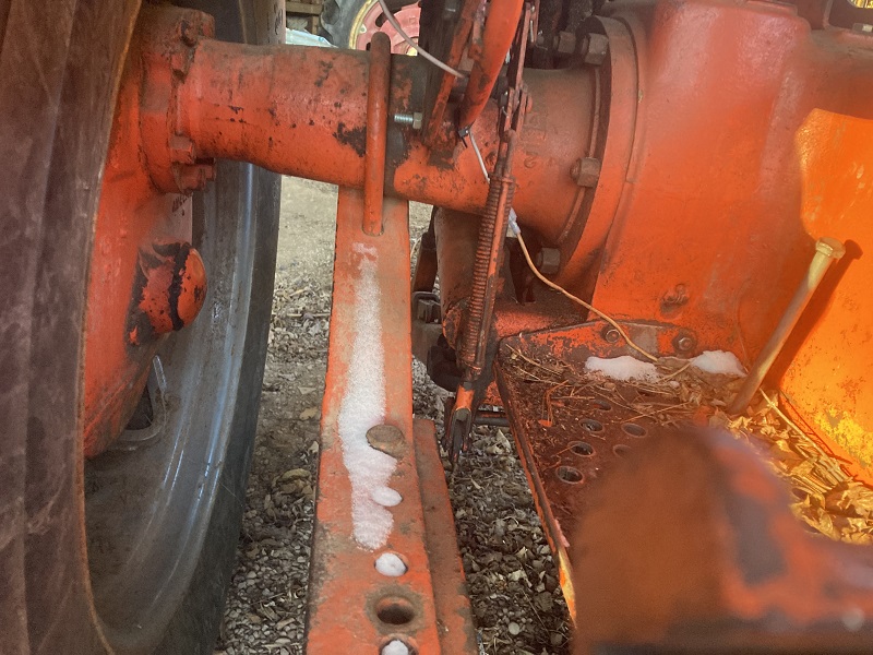  |
Posted By: DrAllis
Date Posted: 23 Jan 2025 at 4:57pm
| A 500 loader on a D17-19 is supposed to use spacers. No spacers on 180-185-190-200. |
Posted By: JoshDay94
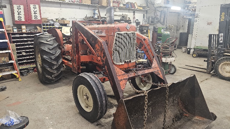
Date Posted: 27 Jan 2025 at 10:18am
 Loader is on. Now just need to plumb up. Thanks for the help guys |