Need WD45 6v wiring diagram
Printed From: Unofficial Allis
Category: Allis Chalmers
Forum Name: Farm Equipment
Forum Description: everything about Allis-Chalmers farm equipment
URL: https://www.allischalmers.com/forum/forum_posts.asp?TID=199335
Printed Date: 18 Mar 2026 at 10:27pm
Software Version: Web Wiz Forums 11.10 - http://www.webwizforums.com
Topic: Need WD45 6v wiring diagram
Posted By: AC WD45
Subject: Need WD45 6v wiring diagram
Date Posted: 18 Jan 2024 at 7:06pm
|
I will start this off by saying I am NOT converting this tractor to 12 volt. It is uniquely set up with 2 6 volt batteries and has been for 50 years. One battery sits in a WC battery box on the frame rail is direct wired to the starter the other is wired factory in it's factory location. That said, Ive had charging issues with the wd45 starting just before I repainted it 10 years aho. I had sold it for a while and they tried to solve the issue by replacing the generator with a 1 wire alternator. No dice. It hasn't been charging at all. Im wondering if the generator was fine all along and if the problem may be elsewhere. I do have the generator and I think I'm going to get it tested, and rebuilt. That said, I've always wondered if I mixed something up or shorted something out when I repainted it. So does anyone have a simple wiring diagram for this thing? I'm going to see what I can come up with. The diagram in the manual I have is really hard to read, the manual is 60+ years old afterall. Thanks! ------------- German Shepherd dad 1957 Allis Chalmers WD45 #WD234847 1951 Allis Chalmers WD #WD88193 |
Replies:
Posted By: steve(ill)
Date Posted: 18 Jan 2024 at 7:33pm
|
https://www.allischalmers.com/forum/wd-45-6-volt-wiring-diagram_topic43088.html%20" rel="nofollow - https://www.allischalmers.com/forum/wd-45-6-volt-wiring-diagram_topic43088.html
------------- Like them all, but love the "B"s. |
Posted By: steve(ill)
Date Posted: 18 Jan 2024 at 7:41pm
|
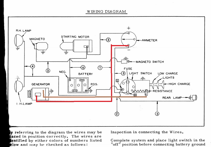
there should be a HOT wire from the amp meter to the Cut Out switch ( small box on the generator) and its OUTPUT wire goes to the "A" terminal on the generator... You should measure 6v at the AMP METER wire on the CUTOUT all the time... the cutout is OPEN when the tractor is not running. The switch CLOSES When the tractor starts and the amp meter and generator are connected together. The GENERATOR then feeds OUT toward the amp meter with a little over 7 VOLTS. The "F" wire on the generator is the GROUND side of the system. It goes to the LIGHT SWITCH and thru a RESISTOR for normal 3 amp charging.. When you have the lights ON and using more power, the SWITCH shorts the "F" wire around the resistor, directly to GROUND and you get a full 8 amp charge.. --You can test battery voltage at the input to the CUT OUT. --You can test OUTPUT of the generator when running by putting a volt meter from the "A" terminal to a GROUND on the tractor frame.. --You can jumper the "F" wire to GROUND to bypass the light switch and check for FULL CHARGE.. --If you measure 7 v out of the generator and only 6 v on the OUPUT of the cutout to the amp meter... then the CUTOUT is not closing / failed. Common modes of failure is the CUTOUT is broken and does not Switch open- closed... and the LIGHT switch is rusty or the resistor has failed and you dont have a GROUND connection....assuming you have voltage output at the generator.
------------- Like them all, but love the "B"s. |
Posted By: Steve in NJ
Date Posted: 18 Jan 2024 at 7:44pm
|
If the 3 position Headlight/Charging switch wasn't grounded correctly, could have been something as simple as that. Generator might have been working. But it's always a good move to have someone go through the Generator and do a complete overhaul on it. Change the arm out in it too. That's the correct way to have it done... Steve@B&B ------------- 39'RC, 43'WC, 48'B, 49'G, 50'WF, 65 Big 10, 67'B-110, 75'716H, 2-620's, & a Motorhead wife |
Posted By: AC WD45
Date Posted: 18 Jan 2024 at 7:50pm
|
Thank you Gentlemen. I think you are nailing it on the head. That light switch has always been iffy. I am going to kick this generator off for a rebuild and hopefully in the next couple weeks I get time to tackle this thing. ------------- German Shepherd dad 1957 Allis Chalmers WD45 #WD234847 1951 Allis Chalmers WD #WD88193 |
Posted By: AC WD45
Date Posted: 18 Jan 2024 at 9:02pm
So here is another question. In the link you provided, the switch has 3 positions, as does mine. In the diagram it shows: Low charge Lights on High charge So my question is, are the lights supposed to turn off in "high charge"? On my tractor currently, the switch operates as In: lights off Middel: forward lights on Full: all lights on I am assuming this is incorrect. Thanks guys. ------------- German Shepherd dad 1957 Allis Chalmers WD45 #WD234847 1951 Allis Chalmers WD #WD88193 |
") steve(ill) wrote:
steve(ill) wrote:Posted By: steve(ill)
Date Posted: 18 Jan 2024 at 10:56pm
|
yes,, that is correct.. ------------- Like them all, but love the "B"s. |
Posted By: Lon(MN)
Date Posted: 19 Jan 2024 at 6:08am
|
Just an idea. The WD45 diesel has a battery box that two six volt batteries would fit in. It used a 12 volt generator with a regulator mounted to the generator. No three position switch was used. ------------- http://lonsallischalmers.com |
Posted By: jaybmiller
Date Posted: 19 Jan 2024 at 6:46am
|
most ( all ?) generators of that period were 'slow' chargers, tractors ran 8-10-12 hours every day to recharge the battery so if you only run 1-4 hrs after starting, the battery doesn't get a full charge. Eventually,it doesn't have enough guts to turn over the starter. Since I'm not a farmer, only use tractors for short time, i tossed alternators into them ( 4, D-14s) since alternators recharge batteries FAST. When keeping 6 volt system, be sure to use BIG battery cables( thick as your thumbs ) ! and CLEAN as ANY itty bit of cable corrosion will stop electrons from flowing. Also check that the 'box' where light switch is in has a GOOD GROUND. Run a separate wire from the switch case to the battery ground, or at least a KNOWN 'good ground'. 6 volt systems need a lot of 'quality care' compared to the 12 volt ones. ------------- 3 D-14s,A-C forklift, B-112 Kubota BX23S lil' TOOT( The Other Orange Tractor) Never burn your bridges, unless you can walk on water |
Posted By: Kenny L.
Date Posted: 19 Jan 2024 at 8:30am
|
Luke, here is another site the is good. Duey's helpful homepage, it's in the farm equipment-knowledge base section, once open go to allis chalmers page 1 |
Posted By: DrAllis
Date Posted: 19 Jan 2024 at 8:56am
| Back in their day, a very high percentage of a "no charge" situation was the fact that the instrument panel wasn't cleanly grounded to the battery box at the lower left hand corner with a coarse threaded screw. The instrument panel has to be grounded for the 3-position switch to work. No ground?? no charge. |
Posted By: jvin248
Date Posted: 19 Jan 2024 at 1:21pm
|
. I have a non AC 6v tractor that was idling and quit because the rpms were not high enough to get the generator outputting anything. That tractor has been rewired for 12v with alternator and it's a completely different tractor now. My folks might have had less battery and starting frogging around back on the old farm. There were time we had to park it on a small hill in the yard to roll-start it. So it's worth investigating generator spin speed needed. .
|
Posted By: AC WD45
Date Posted: 19 Jan 2024 at 5:25pm
|
Got some time to look at it tonight. Just as DR Allis said, the grounding screw is missing. I was unaware the console grounded in this way so I never thought anything of it. I ran in to town to grab food. When i get home I'm going to put the battery backin and jump it off and see what happens ------------- German Shepherd dad 1957 Allis Chalmers WD45 #WD234847 1951 Allis Chalmers WD #WD88193 |
Posted By: DrAllis
Date Posted: 19 Jan 2024 at 5:31pm
| Emery cloth both parts so you have a CLEAN ground !!! |
Posted By: Steve in NJ
Date Posted: 19 Jan 2024 at 5:54pm
|
To insure a good ground at the 3 position switch, run an auxilary wire from the switch mounting screw to the Battery pos. ground. This insures the switch is grounded. The 3 position switch operates this way: IN- low charge through the resistor (2-3 amps) Second pos.- Headlights ON resistor by-passed (full field ground to the Gennie) 4-6 amps depending on third brush setting inside the Gennie) Third pos- Headlights OFF (full field ground to the Gennie- high charge to the Battery. Don't let the Generator fool you. If the 3 position switch is forgotten about and left in the high charge mode, depending on where the third brush is located in the Generator will determine maximum amps put into the Battery. If forgotten about you can and will boil the Battery! Most of those early 6V Gennies can put a max of 8-10 amps at full field mode again depending on where the third brush is set...... HTH Steve@B&B ------------- 39'RC, 43'WC, 48'B, 49'G, 50'WF, 65 Big 10, 67'B-110, 75'716H, 2-620's, & a Motorhead wife |
Posted By: AC WD45
Date Posted: 19 Jan 2024 at 6:35pm
Steve, something is certainly not right here. Being this tractor has been set up with a one wire alternator, I'm trying to get it to just charge for now. Being that my switch is operating horrible incorrectly I'm guessing this is the culprit. However I took a few photos just to err on the side of caution. The red wire from the alternator is going to the toggle switch. The brown wire was just tied off in the loom out of the way. 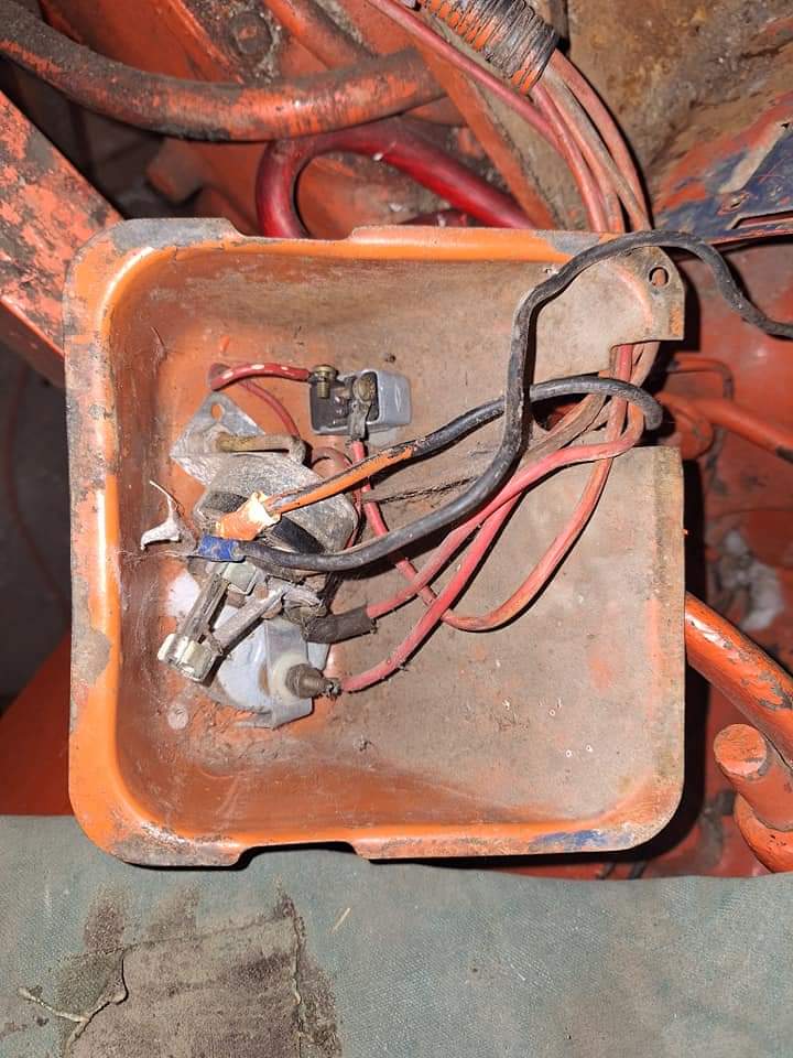 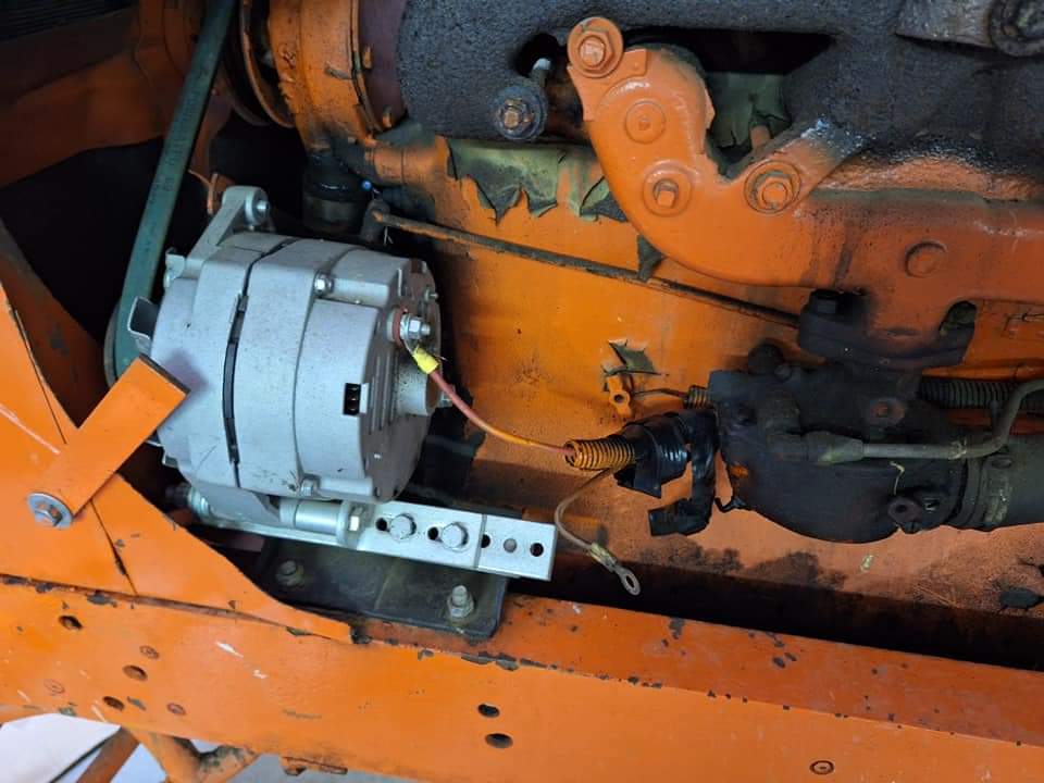 ------------- German Shepherd dad 1957 Allis Chalmers WD45 #WD234847 1951 Allis Chalmers WD #WD88193 |
Posted By: steve(ill)
Date Posted: 19 Jan 2024 at 6:47pm
------------- Like them all, but love the "B"s. |
Posted By: AC WD45
Date Posted: 19 Jan 2024 at 6:54pm
|
Yes that ws with the 2 wire generator. This tractor is currently set up with a 1 wire alternator. In your picture, the colors apear reversed. How is a 1 wire alternator supposed to be wired in? ------------- German Shepherd dad 1957 Allis Chalmers WD45 #WD234847 1951 Allis Chalmers WD #WD88193 |
Posted By: Les Kerf
Date Posted: 19 Jan 2024 at 7:12pm
If you want to use the ammeter (assuming it is functional) then it goes straight to the ammeter. The stock ammeter probably doesn't have adequate range though, and you would be better advised to use a voltmeter instead Otherwise, straight to the battery positive post (assuming it is negative ground, which is most likely).
|
Posted By: steve(ill)
Date Posted: 19 Jan 2024 at 7:48pm
|
take the alternator off... then you have a RED and BROWN wires... Connect them as shown in the drawing.. as Les said, if you dont have an amp meter, then go straight to the battery.
THe RED wire is HOT... on the alternator, that is 12 v NEGATIVE GROUND... On your 6v systme it is 6v POSITIVE GROUND.... the BROWN is the GROUND wire to the light switch.. the RED is the HOT wire to the amp meter, or bypass that directly to the NEG bat terminal. The 1 wire alternator has 1 RED HOT WIRE... the CASE of the alternator is GROUND thru the strap to the engine block, to the battery. 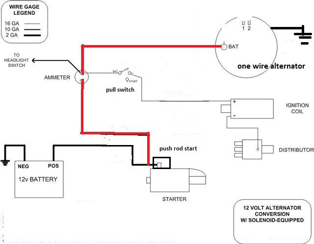 ------------- Like them all, but love the "B"s. |
Posted By: steve(ill)
Date Posted: 19 Jan 2024 at 8:04pm
|
part of the problem is you have 2 of 6v batteries for 12v... and you have an alternator... 99.99% of all alternators are NEGATIVE GROUND.... A Generator can be NEG or POS ground... ALL of the old 6v systems were POSITIVE GROUND.. So which way are you going ??
Which battery terminal is PRESENTLY GROUNDED ? Are you going to leave it this way with the NEW GENERATOR ? The light switch was original to charge ONE 6v battery.. You have TWO.. Are you going to use a 12v generator, or just charge ONE battery ? A 12v system does not use the LIGHT SWITCH, it uses a new VOLTAGE REGULATOR.
------------- Like them all, but love the "B"s. |
Posted By: steve(ill)
Date Posted: 20 Jan 2024 at 9:01am
|
I will start this off by saying I am NOT converting this tractor to 12 volt. It is uniquely set up with 2 6 volt batteries and has been for 50 years. One battery sits in a WC battery box on the frame rail is direct wired to the starter the other is wired factory in it's factory location. So are the batteries in Parallel so you have 6 v to the starter, but TWICE the current ? If so, the alternator would have to be 6V which is VERY UNCOMMON.
------------- Like them all, but love the "B"s. |
Posted By: Steve in NJ
Date Posted: 20 Jan 2024 at 9:40am
|
Hold on here a second!!! I thought you were working with the 6V PG system. You have an Alternator sitting up front??? No wonder you can't make things work. You have Peaches and Apples here. First off, get rid of the Ammeter so you don't burn your Tractor up. Replace it with a Voltmeter for safety. As the guys said, you're working with 12V Negative Ground now, not Pos Grd. If you're going to run a one wire Alternator, you need to run the output wire (heavy wire from the rear of the Alt) to either a junction block or to the Starter motor. In order to start the charging process with a one wire Alternator, you need to rev the engine to 1200-1400 rpm in order to excite the VR to start the charging process. This is why I tell people to move to a 3 wire system. The 3 wire system immediately starts the charging process once the engine is started. Charging should start around 450-500 rpm. Much easier on the engine. Anyway, getting back to the one wire delma, from your Voltmeter + side run a 14 ga. wire to the Starter motor where the Alternator output is. Run a ground wire from the - side of the Voltmeter to either Battery ground or a good CLEAN chassis ground. If you have a couple 6V Batteries in there, toss them out and put a 12V Battery in. Why complicate something that you don't need to complicate. The 3 position light switch shouldn't even be in the equation at all. If you want the Headlights to work, put a universal fused 12V Headlight switch in place of the 3 pos switch. Those 3 position switches do not like the fast moving 12V current running through them. That's fire n' smoke ready to happen. With the Tractor wired the way I explained, once the engine rpm is brought up around 1200 or so, the Voltmeter should start to show a charge between 13.9-14.5 volts. 14.2 being ideal. Now, the proper way to do that is run a 3 wire system like I mentioned above briefly through a key switch to control power on board the Tractor. DO NOT USE A TOGGLE SWITCH to control current from the Alternator. Most general toggle switches are only rated at 10-15 amps tops. You're asking for trouble doing that.... Steve@B&B ------------- 39'RC, 43'WC, 48'B, 49'G, 50'WF, 65 Big 10, 67'B-110, 75'716H, 2-620's, & a Motorhead wife |
Posted By: EPALLIS
Date Posted: 20 Jan 2024 at 11:00am
| I was really interested in this post because I did a complete rewire with a new harness when I was 17 years old with no ones help. All I had was the WD45 operating manual with the wiring diagram shared here. I was so young and dumb! After 9 hours I got it completely done and everything worked great. As soon as I saw that picture and noticed it was an alternator and not a 6 volt Gennie, I said no wonder this is such a long discussion! A picture is worth a 1000 words. Oh, and be sure to save the good Dr's posts on this topic if you have a generator. I didn't know those things back then that he stated and learned the hard way (trial and error). Believe me, they are totally spot on and need to be obeyed and memoralized. Thanks for a great topic!! |
Posted By: AC WD45
Date Posted: 20 Jan 2024 at 1:18pm
It didn't make sense to me either. I will be switching back to the original generator. The system was set up to only charge one battery. A charger was used once or twice a year to maintain the second battery. I'll eventually switch it out to 12v generator charging both batteries. It's a little odd but its the story behind the double battery that counts to me. ------------- German Shepherd dad 1957 Allis Chalmers WD45 #WD234847 1951 Allis Chalmers WD #WD88193 |
Posted By: AC WD45
Date Posted: 20 Jan 2024 at 1:20pm
|
That said thank you gentlemen. I had a feeling the alternator wasn't going to work on this system. I was a little confused when I got it back set up this way. For now I will be putting the original generator back in and wiring things up correctly to determine what is bad. I will report back in a few days. ------------- German Shepherd dad 1957 Allis Chalmers WD45 #WD234847 1951 Allis Chalmers WD #WD88193 |
Posted By: steve(ill)
Date Posted: 20 Jan 2024 at 2:53pm
|
A good explaination of what you hope to do helped a lot.. Your on the right track now.. Just follow the 6V diagram above, Positive ground, good Generator, and ground that light switch ! ------------- Like them all, but love the "B"s. |
Posted By: Les Kerf
Date Posted: 20 Jan 2024 at 3:01pm
|
20+ years ago I purchased a One-wire 6 Volt Negative ground alternator for a Model C that I no longer own; the alternator worked fine other than it did indeed need a quick rev up to excite the field (it literally only took one second to get it going, just flip the throttle up and back down). I didn't like that feature very much but it didn't really seem to harm anything either. |
Posted By: DrAllis
Date Posted: 20 Jan 2024 at 3:13pm
| 30 years ago I quit using single wire Delco alternators because if you didn't use the tractor on a somewhat regular basis, they would run the battery down !!!!!!! Kind of defeated the purpose of the 12volt upgrade. |
Posted By: Ed (Ont)
Date Posted: 20 Jan 2024 at 7:34pm
Yes and still doing the same now on my hotrod Camaro. I guess I will put a shutoff switch in place. Is there any chance of that starting a fire???
|
Posted By: Les Kerf
Date Posted: 20 Jan 2024 at 7:46pm
Interesting. I have owned several of these (still do) and never had that problem; it is pretty easy to check parasitic current draw with a good VOM.
|
Posted By: Steve in NJ
Date Posted: 20 Jan 2024 at 11:04pm
|
The Doc is correct. If anything sits long enough with a one wire Alternator connected directly to the Battery, the Alternator acts as a dynamo and will drain a Battery down to dead. Just depends on the Battery and the electronics in the Alternator. I always preach to my customer's, one of the best things you can invest in is a good Battery shut off switch. If the vehicle sits for long periods of time before its used, its always a good practice to sever the Battery from the vehicle. Doesn't matter what the vehicle is. Its either that, or remove the Battery from the vehicle and put it in an area where you can put a Battery tender on it to keep the Battery "active". You'll get the longevity out of the Battery keeping it active. If it gets pretty cold in your area, remove the Battery and bring it in to a warmer area and put a tender on it. Luke, take your Generator to a local rebuilder and have him throw it on his machine and have him do some load tests on it to see if the unit is working as it should. If it passes all load tests that are put on it, in your mind you know the Gennies good. Then move on to the next item. Make sure the 3 position switch isn't cooked. If it looks okay visually where it doesn't look like it got hot or anything, clean up the instrument box where it bolts to to make sure its grounded correctly. Next would be to inspect the wiring. If any of it is questionable rewire it via the wiring diagram Steve posted for ya. Lastly, have the Battery your using draw tested to make sure your power supply is in tip top shape to use. There's only 3 cells to a 6V Battery, so if you have one cell starting to go away, you've lost a lot of your power source. And a bad cell or low cell can cause the Generator to start a high charge because the low or bad cell in the Battery is putting a load on the system. Once all of that is taken care of, there's no reason in the world why the 6V system won't work correctly. We're not liftin' the space shuttle here. Go to it!...... Steve@B&B ------------- 39'RC, 43'WC, 48'B, 49'G, 50'WF, 65 Big 10, 67'B-110, 75'716H, 2-620's, & a Motorhead wife |
Posted By: Ed (Ont)
Date Posted: 21 Jan 2024 at 3:43pm
What is it that causes those 1 wire to drain battery. Mine will drain battery in couple weeks. I do need to determine for sure if it is the alt tho but pretty sure it is. Problem started when I put the 1 wire on it. This is car I am talking about tho - 70 Camaro. Thx.
|
Posted By: Steve in NJ
Date Posted: 21 Jan 2024 at 5:23pm
|
There are a couple reasons why an Alternator will drain the Battery. If you have an Alternator that has a diode or trio fail, that would cause a ground in the electronics, close the loop in the unit and draw current from the Battery. If the unit is a one wire, because the unit is hooked directly to the Battery, this keeps the magnetic field "active" in the VR. When the magnetic field is constantly activated, it steals mili-volts from the Battery. Eventually, if sitting long enough it can and will drain the Battery. As I mentioned earlier in a post, it acts as a "dynamo" because its constantly active. When you insert a key switch in the middle and control the current to the VR, when the key is off so is the VR. No magnetic field activation, no drain. The voltage sense circuit (#2) on the Alternator, works great on larger Tractors such as the "D" series on up. This circuit can be run parallel with the heavy output circuit and either run to a junction at the dash area, Voltmeter + or Starter solenoid. The voltage sense circuit now monitors current usage and signals the VR when to ramp up the Alternator when loads are applied to the system. The Battery stays "full" the Alternator keeps 14.2 volts throughout the system keeping components working properly, engine running correctly and makes for a happy system. Three wire system is the bestest!  Steve@B&B ------------- 39'RC, 43'WC, 48'B, 49'G, 50'WF, 65 Big 10, 67'B-110, 75'716H, 2-620's, & a Motorhead wife |
Posted By: Les Kerf
Date Posted: 21 Jan 2024 at 7:37pm
Disconnect the wire at the alternator and connect an ammeter in series from the wire to the alternator terminal. Draining the battery in two weeks time will probably require a current draw in excess of ~100 mA or so. if the current draw at that location is less-than 10 milliamps then you need to look elsewhere.
|
Posted By: AC WD45
Date Posted: 22 Jan 2024 at 7:21pm
Generator tested OK so I threw it on and began taking another look at the wiring. I replaced the toggle switch with a proper key switch but I am having a tough time figuring out exactly where everything is supposed to wire up with the key switch.. forgive me as I am no genius when it comes to electrical. Something else I noticed, My 3 position switch appears to be missing the resistor all together? Looks like I may be ordering a new switch after all. Would probablyexplain the incorrect operation of the switch aswell. Right now it acts as a switch between no lights, head lights, and all lights, rather than the correct low charge, lights, high charge.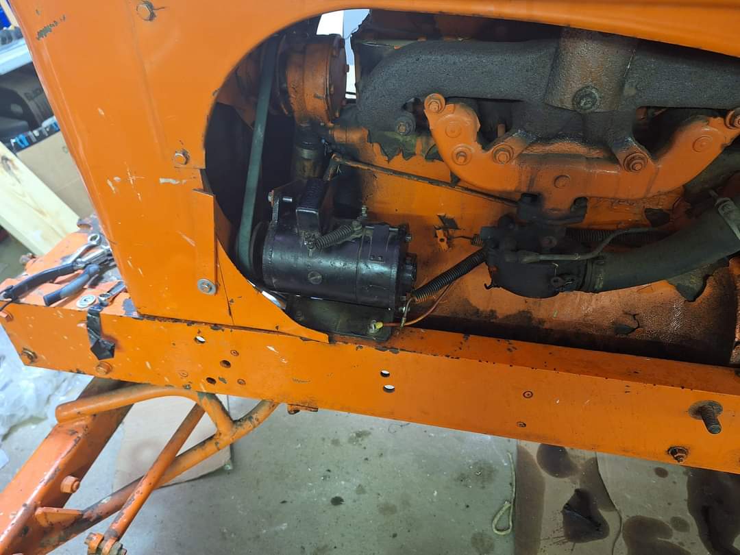 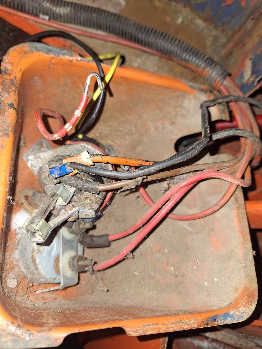 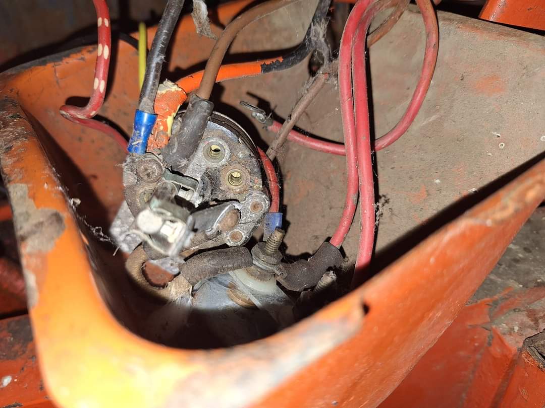 ------------- German Shepherd dad 1957 Allis Chalmers WD45 #WD234847 1951 Allis Chalmers WD #WD88193 |
Posted By: Les Kerf
Date Posted: 22 Jan 2024 at 7:39pm
|
Yup, you need some new parts my friend I recommend a new ammeter as well, also take a close look at those wires with the crimp terminals. Edit: There really is no need for a key switch unless you just want one; all it does is add complexity to a simple system.
|
Posted By: AC WD45
Date Posted: 22 Jan 2024 at 7:49pm
|
How else would the tractor power off and on? This is a WD45, they had a key switch from the factory to my knowledge, maybe not? ------------- German Shepherd dad 1957 Allis Chalmers WD45 #WD234847 1951 Allis Chalmers WD #WD88193 |
Posted By: Alberta Phil
Date Posted: 22 Jan 2024 at 9:25pm
|
Steve at B&B rebuilds those original light switches. He's done a few for me and they come back working like new. That one looks like it needs some attention! |
Posted By: steve(ill)
Date Posted: 22 Jan 2024 at 9:32pm
|
You can use the KEY for power to the COIL for ignition, and to energize the SOLENOID to start the motor............... or you can have a TOGGLE to get power to the COIL ( ON- OFF).. and just have a START BUTTON that you push to energize the SOLENOID to pull in the starter motor... ------------- Like them all, but love the "B"s. |
Posted By: EPALLIS
Date Posted: 22 Jan 2024 at 10:48pm
|
When I did my rewire, I just used an on/off switch. Pull out and its on, push in and it is off. That switch is still hard at work and on the job after 31 years.... Had a used a key switch, I would have lost the key 15 times by now. Keep it simple!
|
Posted By: Steve in NJ
Date Posted: 22 Jan 2024 at 10:52pm
|
The WD45 had a Battery ignition. (Distributor) So a key switch is needed to send power to the Coil. Simple ON/OFF is what was used as OEM. So you did good with a new key switch. If your Tractor was changed over to a Starter solenoid, then you would need either a key crank switch, or pull power off the Ignition switch to power up a start button. Now, looking at that 3 position switch, I can see its all wired incorrectly. Here's what should be on that switch. Jumper wire from the Ammeter minus (-) side to the fuse tower on the H/L switch. Headlight circuit & Tailight circuit (if equipped) to the screw terminal that has the "S" on it. (If you look real close, you'll see letters next to the screws.) Looking at the switch, it looks like the terminal without the screw in it is the "S" terminal that should be used. Generator Field circuit to the resistor leg on the bottom of the switch. Should be no more than 4 wires on that switch. (3 with no Tailight or Work light) There should be a flat resistor on the bottom of that switch. If not, you need one. This is why nothing is working correctly. I have the resistors in stock if interested. As Phil mentioned I do service/rebuild/restore and make parts for those OEM Delco switches. I'm probably the only knuckehead on the planet that does. Take all those wires off and clean up that switch. The only wire that looked correct on that switch was the jumper circuit from the Ammeter to the fuse tower..... Steve@B&B ------------- 39'RC, 43'WC, 48'B, 49'G, 50'WF, 65 Big 10, 67'B-110, 75'716H, 2-620's, & a Motorhead wife |
Posted By: AC WD45
Date Posted: 23 Jan 2024 at 6:04am
Steve, what do you get for a new (refurbished) switch? Being that I have gone this far with it I would almost rather just replace the switch, as it's always been finiky. I was able to find some reciepts, the generator was rebuilt in 2008 and probably less than 50 hours total on the tactor since. I knew grandpa had something done but couldn't remember it it was just the starter or not. ------------- German Shepherd dad 1957 Allis Chalmers WD45 #WD234847 1951 Allis Chalmers WD #WD88193 |
Posted By: Lon(MN)
Date Posted: 23 Jan 2024 at 6:50am
|
Looks like the switch resistor is installed on the generator. ------------- http://lonsallischalmers.com |
Posted By: mdm1
Date Posted: 23 Jan 2024 at 9:02am
|
Just a thought. Buy a 6v regulator and get rid of the cut out and 3 way switch. Then rewire it. I did that on my wd-45 and it's worked just fine. Still 6v. Used it yesterday in 10 deg weather and it started right up and charged fine after sitting for about a month. ------------- Everything is impossible until someone does it! WD45-trip loader 1947 c w/woods belly mower, 1939 B, #3 sickle mower 1944 B, 2 1948 G's. Misc other equipment that my wife calls JUNK! |
Posted By: Les Kerf
Date Posted: 23 Jan 2024 at 10:29am
Good catch! Seems as though that would leave it stuck on low charge. Somebody really hacked that system up.
|
Posted By: steve(ill)
Date Posted: 23 Jan 2024 at 3:44pm
|
Is that a resistor or just a coil of wire ? Looks more like a spring than a resistor.. and it is connected to the CUT OUT ?? Resistor would go to GROUND from "F". -------Somebody really hacked that system up.---- and didnt have a CLUE what they were doing.. 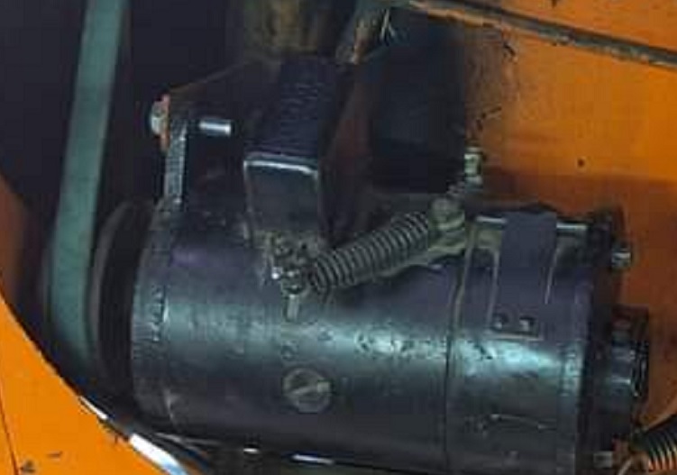 ------------- Like them all, but love the "B"s. |
Posted By: steve(ill)
Date Posted: 23 Jan 2024 at 6:32pm
|
The wire diagram link on the previous page is actually for a B-C-WC type tractor as it is 6v POS ground.. but has a magneto / kill switch / push rod starter.. I looked online and really dont see a WD45 type wire diagram. I marked up the B -C Print to show a COIL- DISTRIBUTOR - STARTER SOLENOID - Key SWITCH in addition to the original 6V POS ground system with the Resistor light switch.. I believe this to be correct. 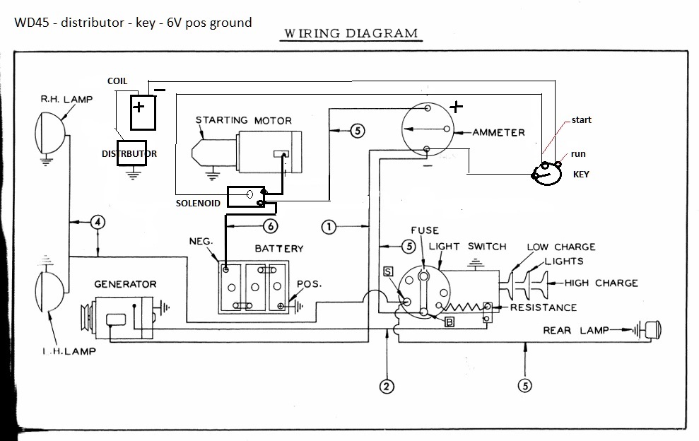 ------------- Like them all, but love the "B"s. |
Posted By: AC WD45
Date Posted: 23 Jan 2024 at 7:19pm
That is just a wire with plastic loom around it. ------------- German Shepherd dad 1957 Allis Chalmers WD45 #WD234847 1951 Allis Chalmers WD #WD88193 |
Posted By: AC WD45
Date Posted: 23 Jan 2024 at 7:23pm
|
I think I've got it now. I runs great and was charging steady 4v in low charge and 7-8.5 in high charge. Lights are non functional, so I think what happened is someone moved things aroind to get the lights working and didn't take account to the functionality of the switch. I do still need to replace the switch, but everything including the ammeter save for the lights ins functional. 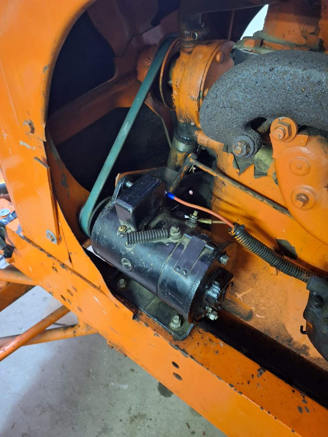 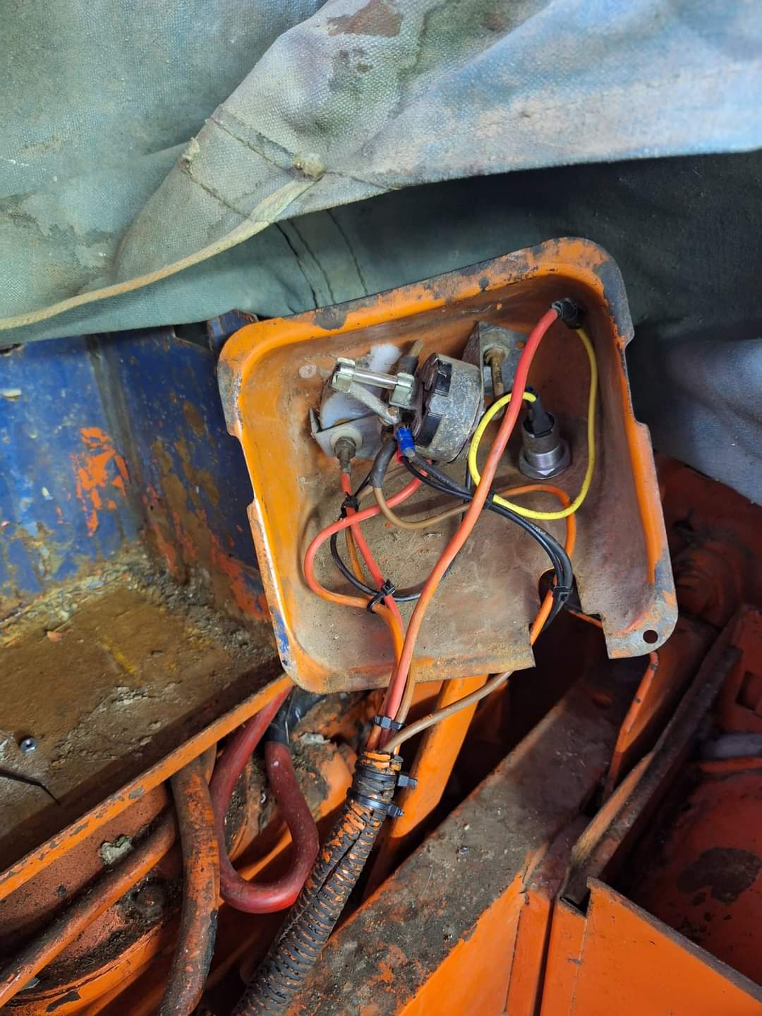 ------------- German Shepherd dad 1957 Allis Chalmers WD45 #WD234847 1951 Allis Chalmers WD #WD88193 |
Posted By: steve(ill)
Date Posted: 23 Jan 2024 at 7:25pm
|
YEP..... that looks a LOT BETTER... Congrats !!
(and your readings were AMPS on the AMP GAUGE ? ) ------------- Like them all, but love the "B"s. |
Posted By: JC-WI
Date Posted: 23 Jan 2024 at 7:55pm
|
Replaced the key switch with a brand new Briggs/Stratton key switch last fall, 70 years of use, been finicky for the last number years of having to set it in a certain position to get it to work. When I changed the this tractor over to the DelcoTron alternator, I put in a new Niehoff lighted ammeter of higher amps and attached the 'on' wire for the regulator to the key switch and rewired the light switch so it was off in the 'IN' position, middle position turned the front headlights on with halogen sealed beams and 32cp bulb in the red tail light on the fender. Third position, all the way out, turned on the FireCracker halogen driving lights bolted ontop of the hood and the rear halogen tail light. Man that tractor had good lights. Was fun cultivating at night with it. With all the lights on it, a generator would not have kept up. Having the alternator was really nice. I had removed the resistor off the light switch too when I had converted it over to 12 volts. ------------- He who says there is no evil has already deceived himself The truth is the truth, sugar coated or not. Trawler II says, "Remember that." |
Posted By: JC-WI
Date Posted: 23 Jan 2024 at 8:03pm
|
Looks like your needing to ground your Generator there at the battery box. A voltage regulator for the gennie would probably be a better idea, then you won't be overcharging the battery. and won't need to worry about grounding the control panel. Also check your ammeter to see if it has continuity across the lugs. Have had several that failed over the years. ------------- He who says there is no evil has already deceived himself The truth is the truth, sugar coated or not. Trawler II says, "Remember that." |
Posted By: AC WD45
Date Posted: 23 Jan 2024 at 8:06pm
|
Yes steve. Forgive me, it has been a long day and I wanted to get this updated before I crash for the night. Thanks again guys. And to Steve at B&B when you see this, I'll send you a PM about a new switch tomorrow. ------------- German Shepherd dad 1957 Allis Chalmers WD45 #WD234847 1951 Allis Chalmers WD #WD88193 |
Posted By: Steve in NJ
Date Posted: 24 Jan 2024 at 8:55am
|
Luke, Providing your switch is rebuildable, you can exchange it for one of my switches ready to go. Remove the rod and knob, cause' that sounds like they're not frozen and working and send your switch in. It's $85. bucks exchange without rod n' knob. If you visit our website, our P/N is 1501-02A. You can also email me at customcircuits@gmail.com. JoAnna can send you an invoice to your email address through Paypal if that works for you. Anyway you want to do it. We're easy here......... Steve@B&B ------------- 39'RC, 43'WC, 48'B, 49'G, 50'WF, 65 Big 10, 67'B-110, 75'716H, 2-620's, & a Motorhead wife |
Posted By: AC WD45
Date Posted: 25 Jan 2024 at 9:57pm
|
Thank you Steve, the wife and I moved into our new place today after months of renovation. Once we get settled I will get in contact! Thanks again to all of you fine gentlemen for helping out with this little endeavor! I don't think this tractor has been wired right since I was riding on Grandpa's knee. ------------- German Shepherd dad 1957 Allis Chalmers WD45 #WD234847 1951 Allis Chalmers WD #WD88193 |