Pictures of Hydraulic Lines #3
Printed From: Unofficial Allis
Category: Allis Chalmers
Forum Name: Farm Equipment
Forum Description: everything about Allis-Chalmers farm equipment
URL: https://www.allischalmers.com/forum/forum_posts.asp?TID=198830
Printed Date: 11 Nov 2025 at 12:33pm
Software Version: Web Wiz Forums 11.10 - http://www.webwizforums.com
Topic: Pictures of Hydraulic Lines #3
Posted By: J. Larsen
Subject: Pictures of Hydraulic Lines #3
Date Posted: 21 Dec 2023 at 4:26pm
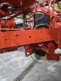
 This shows the return line from the hydraulic cylinders to the pump. This shows the return line from the hydraulic cylinders to the pump.
|
Replies:
Posted By: DrAllis
Date Posted: 21 Dec 2023 at 4:45pm
| I can't see very much. But, what I can see is whomever went to all this work to make a three-point hitch operate on a WD tractor wasted his time and screwed up a good thing that needed NOTHING done to it to make the arms go UP---DOWN--- and HOLD. Your lever on the left side of the steering wheel has a LIFT/LOWER/HOLD position built into it. Why it doesn't work ?? Can't tell you. |
Posted By: Alex09(WI)
Date Posted: 21 Dec 2023 at 9:06pm
|
You are just circulating the oil through the valve when the left lever by the steering wheel is in the lift position. For the lift arms to raise, you have to more the lever to the raise position AND actuate the valve under the seat. From what I can make out of the small pics anyway. ------------- www.awtractor.com A&W TRACTOR 920-598-1287 KEEPING ALLIS-CHALMERS IN THE FIELDS THROUGH THE 21ST CENTURY |
Posted By: HudCo
Date Posted: 22 Dec 2023 at 10:01pm
| looks to me that some one whanted to hook up a double acting cylinder then swith the hose on back for the lift arms , my wd has a pair of remotes plus the remote that works with the lift arms but it is piped and hosed way differant, i can use all three when i am pulling the v16 hayrake , my lift arms and factory single remote still workes off of the lever on the steering wheel oil is routed to my pair of remotes with a diverter valve before a single open center spool the hard part is doing the tubing and hoses so it looks good |
Posted By: J. Larsen
Date Posted: 23 Dec 2023 at 5:23pm
|
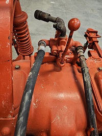
You are pretty close. It doesn't matter what position the left hand lever is in, if you move this control lever, it makes the 3 point go up and down. The hose on the LH side of this pic comes off of the valve on top of the pump. The hose on the right is return, and goes to the bottom of the hyd. reservoir. Evidently an open center hyd. system. 
|
Posted By: J. Larsen
Date Posted: 23 Dec 2023 at 5:37pm
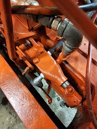
 I began to de-Frankenstein this hyd. system today. I found that the original lines going to the lift cylinders were intact, so I hooked them up to the valve that sets on top of the hyd. pump, with the appropriate line going to the correct ram. The one line that is coming from valve and looking up, is the line that goes to the control valve that set to the left of the seat. After revamping the lift cylinder lines, if you move the control valve to the side of the seat in either direction, the 3 point raises, and will let the arms go down if you nuetralize the lever. I'm guessing that this control valve is part of the Frankenstein process. Dr. Allis recommended that I get an operators manual because it has a lot of good pictures that would be of benefit. I do have an operators manual, but the pictures are very poor and do not show much detail. I began to de-Frankenstein this hyd. system today. I found that the original lines going to the lift cylinders were intact, so I hooked them up to the valve that sets on top of the hyd. pump, with the appropriate line going to the correct ram. The one line that is coming from valve and looking up, is the line that goes to the control valve that set to the left of the seat. After revamping the lift cylinder lines, if you move the control valve to the side of the seat in either direction, the 3 point raises, and will let the arms go down if you nuetralize the lever. I'm guessing that this control valve is part of the Frankenstein process. Dr. Allis recommended that I get an operators manual because it has a lot of good pictures that would be of benefit. I do have an operators manual, but the pictures are very poor and do not show much detail.
|
Posted By: J. Larsen
Date Posted: 23 Dec 2023 at 5:40pm
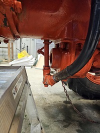
 This is a picture of where the return lines ties into the reservoir. Advice on the control valve and this plumbing would be appreciated. This is a picture of where the return lines ties into the reservoir. Advice on the control valve and this plumbing would be appreciated.Thanks, JL
|
Posted By: Les Kerf
Date Posted: 23 Dec 2023 at 8:00pm
That pipe hanging down there wouldn't last a week around my place
 |
Posted By: SteveM C/IL
Date Posted: 23 Dec 2023 at 8:08pm
the hold valve is screwed into the body. Wrong. Should be locked to plate
|
Posted By: SteveM C/IL
Date Posted: 23 Dec 2023 at 8:12pm
| If you delete the franken coming off the hold valve,your 2 lift cylinders will operate as intended and you need to get all the control linkage adjusted correctly. You will have lift,lower and hold. |
Posted By: HudCo
Date Posted: 23 Dec 2023 at 8:13pm
| thats ok but you still need both lift cylinder hooked to the pump then put a diverter valve or a high preasure ball valve before the double acting valve on the back if you want to keep those two remotes i use a diverter valve because i wanted to seperate all the remotes and lift cyinders |
Posted By: J. Larsen
Date Posted: 31 Dec 2023 at 10:07am
|
I got rid of all of the extra parts and pieces, and got the lift cylinders plumbed correctly. I then started to chase down the linkage to see if it was operating correctly. The "long rod" going from the pump to the control lever was all bound up with rust and worn out cotter pins etc. I got that all freed up and figured out that it was that rod that shut off the pump. Prior to this that rod was stuck in a position that had the pump working constantly. The left hand control lever now works correctly, and now I just need to spend some time to figure out how to interpret the manual and adjust the hold position. This was a real victory for me, and made my day! Thanks to all for the advice. |
Posted By: SteveM C/IL
Date Posted: 31 Dec 2023 at 11:15am
| You are gaining! As I said before you need the 2 plates on the hold valve locked together. Turn that screw out of the body across into the outer plate. Tighten lightly with pliers because finger tight works loose. When lift lever is full up the pump lever should be raised full up also. The little rod hooked in pump lever moves the hold valve. When adjusted correctly the lift lever should be approximately middle (mines a little higher) of the quadrant and hold valve "holding" and pump not pumping. With it like in the picture,the hold valve is locked open and the little rod is just free wheeling the outer plate. When you're finished you will feel a hard spot in the lever about midway as you pull it down from the full up position. That's "hold". HTH |
 J. Larsen wrote: