3 point
Printed From: Unofficial Allis
Category: Allis Chalmers
Forum Name: Farm Equipment
Forum Description: everything about Allis-Chalmers farm equipment
URL: https://www.allischalmers.com/forum/forum_posts.asp?TID=19816
Printed Date: 01 Apr 2026 at 4:17pm
Software Version: Web Wiz Forums 11.10 - http://www.webwizforums.com
Topic: 3 point
Posted By: stuck in the mud
Subject: 3 point
Date Posted: 23 Oct 2010 at 1:18pm
| I there any way that I can use my draw bar to fabricate a 3 pt hitch for my D-17 with out buying the adapter thing that I cant seem to find, it seems like with all the stuff at the old farm and fleet store that I would be able to conjour somethimg up, has anyomne done this in the past? |
Replies:
Posted By: DrAllis
Date Posted: 23 Oct 2010 at 3:21pm
| You can bolt a "T" shaped piece on top of the drawbar that would have pulling pins for the new 3 pt draft arms just ahead and out side of the drawbars original bail. Sway control could be done with chains if needed....depends on how heavy-duty work you're going to do?? Buy two 3pt draft arms and see where they would need to be located and go from there. Remember you need to build a top link attachment point which will go above the PTO shaft area and maybe attach to under the seat frame....what series is this D17?? |
Posted By: DaveKamp
Date Posted: 23 Oct 2010 at 3:55pm
|
Well, it ain't exactly what you're looking for, but it'll give 'ya an idea of what I did... http://www.facebook.com/album.php?aid=40000&id=1130541620&l=51151ccc43 |
Posted By: Gary
Date Posted: 23 Oct 2010 at 5:13pm
|
Try this link:
Gary
http://www.facebook.com/album.php?aid=40000&id=1130541620&l=51151ccc43 - http://www.facebook.com/album.php?aid=40000&id=1130541620&l=51151ccc43
|
Posted By: DrAllis
Date Posted: 23 Oct 2010 at 6:10pm
| My only criticism of the design would be the top link pin hole location may need to be lower down....like maybe 4 to 6 inches?? there could come a time when you can't pick something up high enough and a lower pin hole location will help tilt the implement up higher......other than that it looks well designed and rugged. What do you have for sway control?? |
Posted By: stuck in the mud
Date Posted: 23 Oct 2010 at 8:20pm
| That is pretty sweet looks like just what I need, I'll have to buy a few tools and a welder or just go to the neighbor, at first I thought you had my tractor in your barn but mines a '58, so if I went that route I wouldnt need my draw bar but I could still use the 2 bottom plow that came with the tractor |
Posted By: stuck in the mud
Date Posted: 23 Oct 2010 at 8:22pm
| Thanks Dave |
Posted By: DaveKamp
Date Posted: 24 Oct 2010 at 2:12am
|
THanks for correcting the link, Gary- didn't realize it didn't recognize it as a 'link'... Doc- No sway control on it yet, but I figured that if I needed it, I'd put some chains with hooks on there, and just snap 'em where it worked right. Pin hole height... I left enough material in there to make additional choices, but based my location on other CAT1 designs. One thing I DID do, is left extra holes in the lower bracket, so if I needed to change geometry, I could move the lower-end pins to any of the other holes and change lower angles substantially. That adjustable top link is a handy thing... found it at a flea-market for $10... seems to resolve most any positioning challenge. |
Posted By: BobHnwO
Date Posted: 24 Oct 2010 at 8:01am
This is how I made one of mine,I've done several,easy to build.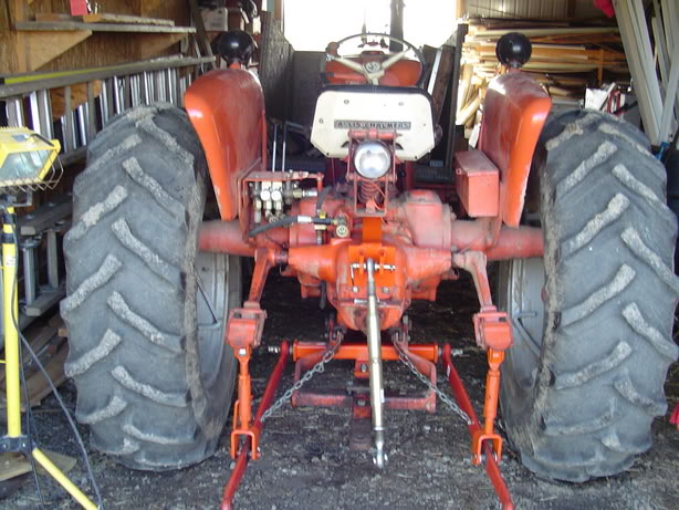
------------- Why do today what you can put off til tomorrow. |
Posted By: Gary
Date Posted: 24 Oct 2010 at 8:29am
|
Dave What an excellent "Step by Step" illustration of fabricating your 3 Pt. Conversion.
One big feature of the D-17 that you loose in your design is the "Traction Booster"
since you are not pulling from the Snap Coupler.
May not be an issue for most users though.
Gary
|
Posted By: Brian G. NY
Date Posted: 24 Oct 2010 at 8:59am
Here are 3 pics of a 3PH on a D-17 at a local dealership.   
|
Posted By: Brian G. NY
Date Posted: 24 Oct 2010 at 9:03am
|
This is the 3PH on my D-17 which was fabricated by the Prior owner. There are a few things I don't like about this set up but I really like the anti-sway setup; there is no side to side movement at all when I use my Bush Hog. |

Posted By: stuck in the mud
Date Posted: 24 Oct 2010 at 12:50pm
| Great pics to all thanks much now I have a lot of ideas, now I can sit on the ground behind my D-17 and think how I wannt to go |
Posted By: Brian S(NY)
Date Posted: 24 Oct 2010 at 1:45pm
|
well thats neat. I have an extra unit for my snap coupler d-15 which I may put on some day. The adapter I have on it now doesnt allow me to swing the draw bar. Not very coneinent. ------------- God made man.Sam colt made man equal. |
Posted By: DaveKamp
Date Posted: 24 Oct 2010 at 8:56pm
|
You're right, Gary, and I considered making the cross-bar 'float', and having a drawbar going from the crossbar, so that draft load goes to the snap-coupler, not so much for draft control, but so that draft forces didn't shear off those four big bolts... but as I thought about it more, I decided that if I were running ground-engaging implements, I would probably sooner get some Allis snap-coupler imps, and just yank the lift arms' n stuff and get it all out of the way... and use the snap-coupler implements as they were originally intended. I use my 3ph most often for either a lifting boom, or a rear blade, box blade, or a trailer-hitch attachment... One of these days I'll probably make a doohicky that'll pick up and carry a pallet-load of bricks. I'm currently getting ready to install a live hydraulics system... at that point, I'll be mounting a little backhoe attachment that is lifted into position using the 3-point lower lift arms... it's the backhoe attachment that became my motivation for putting a 3-point on in the first place. Ah, and notice- Ohio Bob's cross-bar, like mine, is spaced out much wider than the others shown. It has some effect on how implements pull, but having 'em spaced wide, with straighter arms, means the spherical joints are in the middle of their swing-range. |
Posted By: E7018
Date Posted: 24 Oct 2010 at 9:59pm
| I am the guy that you got the hydraulic parts from. Need pictures of the hydraulic system going together. I did see that some crankshaft pulleys don't have the 4 - 7/16" bolt holes in them that are needed to bolt that flange - hub deal to. That reducer bushing in the oil tank is one of those strainer deals. That system had water in oil plenty bad. Make sure you take that strainer out of the tank and clean it good before it goes together. |
Posted By: DaveKamp
Date Posted: 24 Oct 2010 at 11:01pm
| Yeah, I looked it over already, and I DO have the proper holes for the coupler, just haven't gotten a round-tuit re. yanking the radiator to install the coupler and shaft. I'll be using part of the bracketry, and have started a new bracket that'll not only hold the pump, it'll move the tank to one siderail, and make attachment points for a snowblade, additional lights, and probably a few other things... I'll post those pix later. |
Posted By: stuck in the mud
Date Posted: 25 Oct 2010 at 3:30am
| So what is the traction booster that gary mentioned and it seems to me that by useing the 3pt it puts all the weight on the rear wheels where as useing the snap coupler when there is resistance from the implement it would be transfered to the whole tractor. I would just use the snap coupler since I have allready have a plow but now I need a disc and havent found one with the S.C. |
Posted By: DaveKamp
Date Posted: 25 Oct 2010 at 7:13am
|
Both the snap hitch system AND the 3-point will fully lift the implement, hence they both put all the weight on the rear wheels. The Traction Booster system allows the tractor to adjust implement depth based on draft load. It is a comparative system to other draft/depth control systems of the time. Here's a description of the Ferguson: http://www.ytmag.com/articles/artint261.htm The Traction Booster system incorporates lift arm/implement hydraulic output with a sensing valve coupled to the drawbar snap coupler bell located under the transmission... tension on the drawbar modulates the lift arms to keep steady progress through varying soil. Since my lower arms bear draft load directly to the transaxle, and don't use the coupler, changing draft load on the 3-point does NOT call the traction-booster into action. To make a 3-point that DOES, the lower lift arm bracket needs to 'float'. One way I could have done it, is to make a rigid bracket, from which that crossbar is attached by pins or bolts through slotted holes... probably need no more than an inch of travel... on the front of the crossbar, would be a fixture that rigidly pins to either the original drawbar, or to a drawbar that's been cut down specifically for connection to the 3-point bracket. In doing so, two things would result: 1) draft loads on the 3-point arms would be transferred to the snap-coupler bell, allowing the traction-booster feedback to function. 2) draft loads would not be applied to the four bolts where I connected my lower bracket. The downside, is that the lower bracket would slop around a little bit. Someday, I very well may take the time to do this... I didn't do it at the time because I needed 3-point lifting capability on fairly short notice, and didn't have immediate need for the traction booster system. |
Posted By: DaveKamp
Date Posted: 25 Oct 2010 at 7:17am
|
One simple way a guy could MAKE a lower bracket that ALLOWED traction-booster to work... Is to swing by your local implement store and get a 3-point drawbar: http://www.northerntool.com/shop/tools/product_200315625_200315625 And bolt it to the original drawbar, about the same general location as where my crossbar is installed. You'd wanna bolt it on securely, with extra straps going from the outer edges to the drawbar... and you'd also want to put some sort of 'stop bracket' over the drawbar to keep it from flip-flopping right to left... but with that in place, connect your lift arms right there, and you'll have draft control in a quick-and-dirty timeframe. |
Posted By: stuck in the mud
Date Posted: 05 Nov 2010 at 12:12pm
| Hi Dave what do you think it would cost me to have someone weld me up something like that mainly the top piece that goes under the seat, I just got this tractor and need toys for it, I could make a template out of cardboard or masonite but I dont have the meatl, devil's toothpick or a welder I do have a son-in-law that is at a local college is a welding class and he is looking for stuff to do, how thick is that steel you used, I can usually fabricate i am just lacking in some of the tools |
Posted By: DaveKamp
Date Posted: 06 Nov 2010 at 9:18pm
|
Hee hee... well, I have no clue. When I need things cut, sized, and welded, I just do it myself... I think if you had templates cut, and told a fab guy the sizes, he could give you a pretty good guess... The side plates are around 3/4" thick... the tube is about 4" square, probably 1/2" wall. To make sure the fit and alignment are correct, use a jack to hold it against the bottom of the tractor (like I did). You don't want to be in a situation where the bolts don't run down flush... or won't line up. I'll hafta take a tape-measure to it to tell you width... check back tomorrow! |