Allis 200 alt Installation
Printed From: Unofficial Allis
Category: Allis Chalmers
Forum Name: Farm Equipment
Forum Description: everything about Allis-Chalmers farm equipment
URL: https://www.allischalmers.com/forum/forum_posts.asp?TID=195485
Printed Date: 12 Nov 2025 at 5:58pm
Software Version: Web Wiz Forums 11.10 - http://www.webwizforums.com
Topic: Allis 200 alt Installation
Posted By: captaindana
Subject: Allis 200 alt Installation
Date Posted: 01 Jun 2023 at 2:25pm
So the new alt apparently is single wire. I’m thinking the 2wires on bat post on old alt go on the new alt bat post. Also guess to tape over / remove the other 2 or 3 wires. 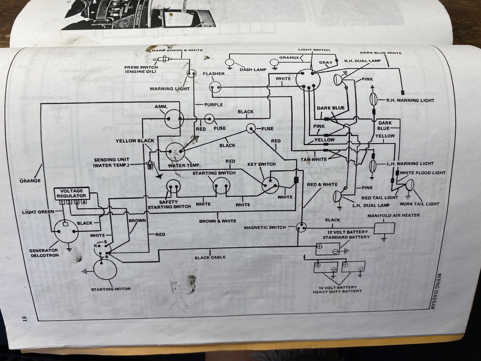 ------------- Blue Skies and Tail Winds Dana |
Replies:
Posted By: steve(ill)
Date Posted: 01 Jun 2023 at 4:01pm
|
YES... one of the BIG TERMINAL wires goes to the amp meter / then battery... Not sure what the other one does, but feeds something HOT all the time ( head light switch ? accessories ?)... The two small Terminals were signal wires and might have been part of the original voltage regulator ... just tape off and tie out of the way.
------------- Like them all, but love the "B"s. |
Posted By: DaveKamp
Date Posted: 02 Jun 2023 at 10:23pm
|
Green wire on terminal 1 is the field supply. Regulator increases field current when it's voltage sense input is lower than the target voltage, and decreases field current when it's voltage sense is higher. Brown and white on terminal 2 is voltage sense for the regulator. The regulator uses this to determine how much field current should be boosted or reduced to maintain the target voltage. Terminal 3 is connected to battery, that is battery power source for the regulator. When the engine starts, the alternator spins, however, there's no field current until it can be sourced from somewhere... and Terminal 3 is where that comes from. The regulator draws it's field supply current through this terminal. Terminal 4 is for a dash indicator, which is not used in this application. The large orange wire coming from left terminal, is alternator output... it goes to the right side of the ammeter. With battery on the left terminal, whenever the alternator is not charging, the ammeter needle will indicate a discharge. When the alternator is charging, current flow will cause the ammeter needle to swing towards the charge side. On the alternator, the remaining 'big' wire shown, is going to the GROUND terminal on the alternator case. This is a ground wire for the alternator's field, as it is not internally grounded. In most automotive applications, this connection is just internally grounded, but on heavy-duty/industrial type applications, it is not unusual to have a different regulation (where shunt resistance is AFTER, rather than BEFORE the alternator field) or a dual battery 12/24v system... in which case, this post is used in a different wiring scheme. In the case of your new alternator, none of these connections except for the BATTERY connection is used, and the ground is connected to case internally. ------------- Ten Amendments, Ten Commandments, and one Golden Rule solve most every problem. Citrus hand-cleaner with Pumice does the rest. |
Posted By: captaindana
Date Posted: 03 Jun 2023 at 4:34am
|
Thanks Steve and Dave. She works grrreeeaaatttt! ------------- Blue Skies and Tail Winds Dana |
Posted By: captaindana
Date Posted: 03 Jun 2023 at 5:08am
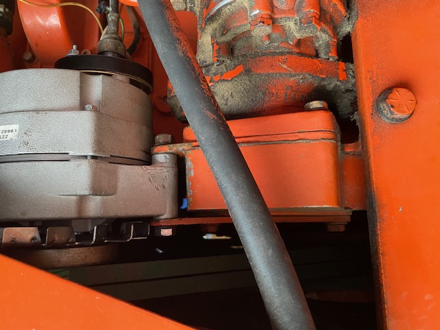 I suppose lowering the pivot could be done but not easily for me anyways🙀 ------------- Blue Skies and Tail Winds Dana |
Posted By: captaindana
Date Posted: 03 Jun 2023 at 5:10am
 Notice the angle of the tach drive. It’s NOT from tension from the cable, it IS he way it’s made….for some seemingly strange reason to me. ------------- Blue Skies and Tail Winds Dana |
Posted By: steve(ill)
Date Posted: 03 Jun 2023 at 12:47pm
|
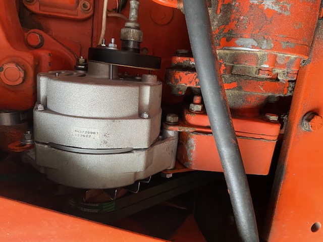
yea... i dont see removing the mounting plates and redoing the holes... but a possibility might be to egg shape the mount holes with a die grinder ( while still on the tractor) and allowing the pivot bolt to drop down 1/8 inch or better.... just another way to accomplish the same end result !
an inch longer belt might allow the alternator to set OUT a little further from the thermostat housing... another possibility ? ------------- Like them all, but love the "B"s. |