Mini Denso 1 wire conversion
Printed From: Unofficial Allis
Category: Allis Chalmers
Forum Name: Farm Equipment
Forum Description: everything about Allis-Chalmers farm equipment
URL: https://www.allischalmers.com/forum/forum_posts.asp?TID=193589
Printed Date: 12 Feb 2025 at 7:44am
Software Version: Web Wiz Forums 11.10 - http://www.webwizforums.com
Topic: Mini Denso 1 wire conversion
Posted By: captaindana
Subject: Mini Denso 1 wire conversion
Date Posted: 18 Feb 2023 at 4:07pm
So this is my fifth mini Denso one wire alternator conversion the first four were on AC’s this happens to be on an Oliver 77 however the batteries wiring coils alternators and voltmeters etc. are all identical. This one doesn’t seem to get excited and I’m wondering can I jump a wire from one of the two terminals you see here back to the main post output? Or…??? Thanks! Dana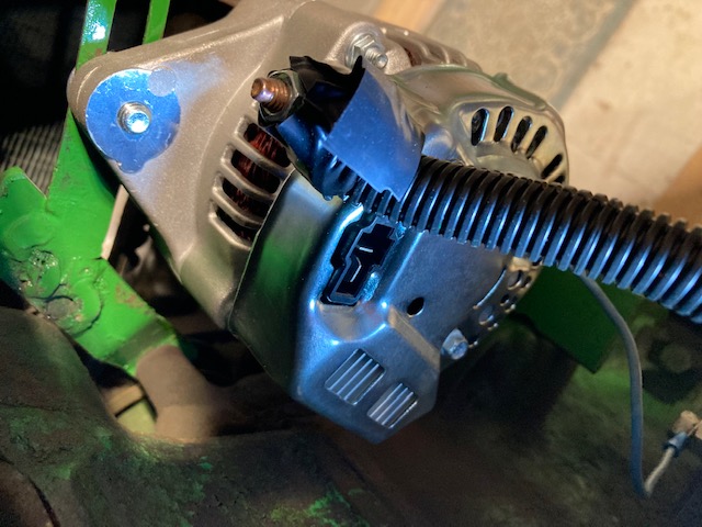 ------------- Blue Skies and Tail Winds Dana |
Replies:
Posted By: jaybmiller
Date Posted: 18 Feb 2023 at 5:04pm
|
Hmm, maybe paint the Oilver ORANGE ??  OK, use a smaller pulley on the alternator or higher revs ( to start the charge mode...) pretty sure there's some MINIMUM RPM the alternator has to run at to 'start' the process for sure someone will respond. I've only used the CS130 series, so 3 wire... I like the 'idiot light' hookup.it also says 'the belt is broken' ------------- 3 D-14s,A-C forklift, B-112 Kubota BX23S lil' TOOT( The Other Orange Tractor) Never burn your bridges, unless you can walk on water |
Posted By: im4racin
Date Posted: 18 Feb 2023 at 7:45pm
| Take a jumper from batt lug and touch the others one at a time while running. It should excite. If there’s is an IG or L terminal label it will be the IG terminal that will get it started. |
Posted By: steve(ill)
Date Posted: 18 Feb 2023 at 8:28pm
|
if the two terminals are connected INSIDE... then it looks like this... power to #2 and signal to #1 .... you might try a pushbutton to send 12 v to one terminal and see it that KICKS it in... might not need a constant voltage to it while running.. but it cant hurt. Like mentioned above, just TOUCH the BIG LUG terminal to the small "L" (#1) momentarily and see if that works... may not need CONSTANT voltage. 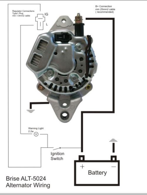 ------------- Like them all, but love the "B"s. |
Posted By: captaindana
Date Posted: 19 Feb 2023 at 5:21am
|
Thanks! Steve I did not know the 2 terminals were tied together nor are they marked. Question…if I wanted to excite those terminals when the ign sw is ON couldn’t I just jump a wire from + side of coil to them? ------------- Blue Skies and Tail Winds Dana |
Posted By: im4racin
Date Posted: 19 Feb 2023 at 6:49am
| I think the IG terminal has a diode in the alt to prevent back feed. Try it and if it keeps running after key off then you need to add a diode in that wire. |
Posted By: jaybmiller
Date Posted: 19 Feb 2023 at 6:54am
|
Those 2 terminal may NOT be connected inside ! I've read 'somewhere on the net' the mfr uses the same 'plastic connector' for 3 wire and 1 wire. In a 1 wire, it's just serves as a 'hole filler'. A proper 'filler' piece would need to be designed,injection molded,put in inventory and yeesh PITA when the wrong piece gets on the assembly line !!! ------------- 3 D-14s,A-C forklift, B-112 Kubota BX23S lil' TOOT( The Other Orange Tractor) Never burn your bridges, unless you can walk on water |
Posted By: steve(ill)
Date Posted: 19 Feb 2023 at 8:05am
|
yes captain, you can use a hard wire from the + coil to the alternator.. Then the wire is turned OFF when the key is OFF.... as im4racin said, the alternator might then generate enough voltage to FEED BACK to the coil and keep the motor from shutting off ... thats why the SWITCH is shown in the drawing, so no power runs BACK to the coil. With motor running, just use a 12 inch jumper and TOUCH the BIG LUG to one of the smaller terminals and see if the alternator KICKS IN.... thats a simple test prior to doing all the hard wiring.. As jay mentioned in the beginning, some guys just buy an inch small pulley and put on the alternator so it SPINS UP to a higher RPM and normally kicks in.. ------------- Like them all, but love the "B"s. |
Posted By: captaindana
Date Posted: 19 Feb 2023 at 3:19pm
Ok i’m pretty sure those two small terminals are not hooked to anything just as Jay said. It will not excite wide open rpm’s so I’m going to post a picture of the pulley that I am using I don’t know if I can get a smaller one can I?? And I imagine it is metric as is the mounting hole and tension hole.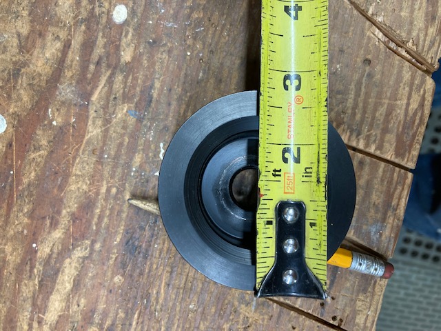 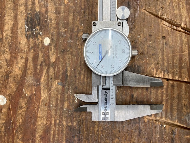 ------------- Blue Skies and Tail Winds Dana |
Posted By: steve(ill)
Date Posted: 19 Feb 2023 at 5:11pm
|
the "STANDARD" alternator pulley is 2.7 inch diameter and 17 mm ( .669 inch) hole... They do make 2 inch diameter pulleys ( some vendors)... you may want to VERIFY the hole size.
some of the smaller alternators are 15 mm .. (.591 inch) ------------- Like them all, but love the "B"s. |
Posted By: steve(ill)
Date Posted: 19 Feb 2023 at 5:34pm
|
I am surprised that the alternator will not AUTO EXCITE at full engine throttle... Is is possible the alternator is BAD ? Is it new ? What size pulley is on the crank shaft... divide that by 2.7 inch and multiply by HIGH RPM to get the alternator RPM. 15 mm HOLE pulleys are not that common.. You may have to turn that one down on the lathe, or get a 2 inch dia - 1/2 inch hole pulley and have it reamed out to .591 " ....... but i would verify the alternator is good first... but hard to do if it will no Excite.... a "TEST" might be to switch alternators with another tractor.
------------- Like them all, but love the "B"s. |
Posted By: Steve in NJ
Date Posted: 19 Feb 2023 at 6:00pm
|
Most of the mini Denso mainshafts are 15mm. If you wire the Alternator as a three wire, you don't have to worry about smaller pulleys and what not. It's two more wires you have to run. The IGN wire runs to the key switch ignition source, so when you turn the key in the ON position, you send 12 volts to the VR to turn it on. The "L" is the voltage sense circuit you can run to the Battery side of the Starter solenoid, or Starter motor itself. Run that parallell with the Alternator's output wire and connect them together at the Starter or Battery circuit. The voltage sense circuit will monitor current usage at the Starter. It will also keep the Battery "full". One thing people don't take into consideration with these one wire systems, is the voltage drop from the Alternator to the Starter motor or Battery circuit. Sometimes it could be up to a volt. Doesn't sound like much, but it you don't have the voltage sense circuit hooked up to monitor and current flow in the system, it can't send a signal to the Alternator to ramp up and "balance" the voltage in the whole system to 14.2 volts. Without the sense circuit, if you turn on the Headlights, worklamp, or you may have a sprayer hooked up to the Tractor, ignition system needs full power, with no sense circuit, your suckin' off the Battery and the Battery may not have enough reserve to sustain the draw on the system between the voltage drop, and the draw. You may have to put a 1 amp/50V diode in the IG circuit to eliminate run-on when the key is off. Three wire. Three wire. That's the way to fly on a Tractor. No revvin' the crap outta' the engine to start the charging, no little pulleys, no low current in the system, no burnt points, or E.I. and no low Battery issues. Steve@B&B ------------- 39'RC, 43'WC, 48'B, 49'G, 50'WF, 65 Big 10, 67'B-110, 75'716H, 2-620's, & a Motorhead wife |
Posted By: captaindana
Date Posted: 19 Feb 2023 at 6:59pm
|
I’ll check/verify if new alt is good or not first thing tomorrow. Thanks. Dana ------------- Blue Skies and Tail Winds Dana |
Posted By: captaindana
Date Posted: 19 Feb 2023 at 7:02pm
|
As I said I purchased 5 mini’s and this is the last one I’m stuck with, next purchases will be the 3 wire alts. Also none of these rigs have anything electric on them ‘cept ignition. Lights are just for looks! Jeesh! ------------- Blue Skies and Tail Winds Dana |
Posted By: im4racin
Date Posted: 19 Feb 2023 at 9:28pm
| So running and jumper to the IG terminal didn't get it charging? |
Posted By: captaindana
Date Posted: 20 Feb 2023 at 5:16pm
|
OK so the T-shaped two terminals which are unmarked on the alternator we put the spade on the top of the T terminal over to the output post of the alternator and it works great there will be another wire tomorrow from the bottom spade of the tee to the starter lug. THANKS TO ALL. Dana ------------- Blue Skies and Tail Winds Dana |
Posted By: steve(ill)
Date Posted: 20 Feb 2023 at 5:28pm
|
the bottom is excitation that normally needs a SWITCH or resistor or diode in the line from the coil.. If you, you may feed BACKWARD and have voltage to the coil so the motor will continue to run.
OK, your thinking the excitation line could go to the STARTER and not the COIL.. Your thinking it will have a little voltage drop in the wire due to its LENGTH... and it should not continue to send power to the coil for run on...... that might work... With out a SWITCH in the line, it is possible it will feed back and drain the battery over time... All depends on the condition of the DIODES inside...... try it and find out ! ------------- Like them all, but love the "B"s. |
Posted By: Stan R
Date Posted: 20 Feb 2023 at 6:16pm
| Steve set me up with a 3 wire alternator, switch, electronic ignition, etc. few years ago and I was able to re-use the old generator pulley. D17 IV. |
Posted By: Steve in NJ
Date Posted: 20 Feb 2023 at 8:19pm
|
Ya did good today Cap! I'm gonna turn you into a wiring guru. Great time on the phone today! That was a blast! Have fun man! Steve@B&B ------------- 39'RC, 43'WC, 48'B, 49'G, 50'WF, 65 Big 10, 67'B-110, 75'716H, 2-620's, & a Motorhead wife |