Crankshaft end play
Printed From: Unofficial Allis
Category: Allis Chalmers
Forum Name: Farm Equipment
Forum Description: everything about Allis-Chalmers farm equipment
URL: https://www.allischalmers.com/forum/forum_posts.asp?TID=184466
Printed Date: 12 Mar 2026 at 11:27pm
Software Version: Web Wiz Forums 11.10 - http://www.webwizforums.com
Topic: Crankshaft end play
Posted By: ac55tractor
Subject: Crankshaft end play
Date Posted: 08 Nov 2021 at 8:30am
|
Hi Everyone. I just pulled apart my 1955 Allis B engine. The crankshaft had .070 end play. .044 of that wear was from the thrust bearing. The area of the crank that rides against the thrust bearing was worn back .026. I was able to determine that originally the distance from the back face of the timimg gear to where the crankshaft rides against the back of the thrust bearing is 1.625 from the factory. Now, because of the ware on the crankshaft it now measures 1.651. I sent the crank to the local machine shop. The owner said that he could grind that surface back from .026 to .032 and all I needed to do was to make and install a .032 shim placed between the thrust bearing and the crankshaft to compensate for the difference in order to correct the error. He refused to build it up with weld. He didn't want to be responsible for any damage resulting from welding. I have a small milling machine with a rotary table to make a shim. I am just not so sure about what he suggested or what material to make the shim out of. I hope that I am clear. Any advice would be appreciated. Thanks
|
Replies:
Posted By: steve(ill)
Date Posted: 08 Nov 2021 at 8:35am
|
i had a similar problem on a B ... 15 years ago... cant give you exact numbers, but i took the gear off and machined a STEP on the back of the gear so i could push it on about .040 further to get the dimension right for the bearing... you want something small like .002 or .005 clearance .............. The gear is about an inch wide, pushing it on .040 further dont hurt the gear alignment to others. ------------- Like them all, but love the "B"s. |
Posted By: ac55tractor
Date Posted: 08 Nov 2021 at 8:53am
|
That's a great idea. I believe I saw that in an earlier post. I had some questions about that. I lightly checked hardness of the gear at the teeth with a hand file. It seemed a bit hard to machine. Now thinking about it. I wonder if only the teeth are hardened and the rest of the gear was not, so that's how you were able to machine it. |
Posted By: steve(ill)
Date Posted: 08 Nov 2021 at 8:55am
|
YEP... i remember thinking the same thing when i tried it... Must be soft as i sure dont remember machining being a problem. ------------- Like them all, but love the "B"s. |
Posted By: ac55tractor
Date Posted: 08 Nov 2021 at 9:02am
|
Thanks for the reply. Also in the earlier posts there were different opinions on how to
reinstall the gear. I wasn't sure of the best way to approach that. There is a .003 press fit, and lining up the key way. I would have to get the heat just right. I have to get outside right now so there maybe a delay in a response. Best to you Steve
|
Posted By: steve(ill)
Date Posted: 08 Nov 2021 at 9:21am
|
Seems like i warmed it up maybe 400 degrees with a propane torch and pushed it on.... yea... getting they key aligned is always the trick part..... dont remember, is it a straight key where you can set at the FRONT of the shaft, get the gear and shaft started together, then drive the gear and key on ? ....... again, dont recall a big problem in the install. Heating the gear to expand it does help. ------------- Like them all, but love the "B"s. |
Posted By: PaulB
Date Posted: 08 Nov 2021 at 10:08am
|
When I send a BE/CE crankshaft to get reground I remove the Crank gear, before I send it This allows the front of the crankshaft to be ground back where the gear presses on to get proper end play. All quality crank grinders should be dong this, any other way is just dong a band-aid fix for something that is messed up. ------------- If it was fun to pull in LOW gear, I could have a John Deere. Real pullers don't have speed limits. If you can't make it GO... make it SHINY |
Posted By: steve(ill)
Date Posted: 08 Nov 2021 at 12:31pm
|
well if your sending off to someone to do the work for you, that would work.. My crank didnt need ground, it just needed the gear pushed on FURTHER... and cutting a step in the gear served that purpose very well. ------------- Like them all, but love the "B"s. |
Posted By: ac55tractor
Date Posted: 08 Nov 2021 at 1:16pm
|
I asked the owner of the automotive machine shop to contact me
before he started so I could stop by here at the forum and get some ideas on how to proceed, before giving him
directions. You guys have great ideas. Paul, your idea
came to mind just before dropping it off. I pushed the gear off about an
inch and pulled the woodrift key out, hoping that hitting the shaft where the gear butted and reestablishing the 1.625 step over would be a satisfactory option. I was a bit confused over the earlier posts on this subject before posting here today. I guess that I should have stopped by here
first. At that time, I assumed that the gear was too hard to machine. Thanks Men Steve Raymond, Maine EIEIO
|
Posted By: ac55tractor
Date Posted: 13 Dec 2021 at 11:53am
|
I need a second opinion please. I got my crankshaft back from the machine shop just after Thanksgiving. He had to remove .037 to clean up the warn area on the crankshaft. Then he came out to 1.628 (the thickness of the thrust bearing 1.625 plus .003) and then cleaned the face where the gear presses against. With the crankshaft now pushed out by .037, I was wondering is it going to be necessary to remove .037 from the back of the pulley so that the belt will line up? Thanks in advance Steve
|
Posted By: SteveM C/IL
Date Posted: 13 Dec 2021 at 12:29pm
| Not for only .037.... .370 maybe. Your only talking 1/32 in |
Posted By: steve(ill)
Date Posted: 13 Dec 2021 at 3:06pm
|
Steve is right.. you will never see .037 offset. ------------- Like them all, but love the "B"s. |
Posted By: ac55tractor
Date Posted: 13 Dec 2021 at 3:58pm
|
Thanks for the reply's. One less thing to worry about. I am getting ready to install the bearings. All of the bearing journals are now -.010 except for the center main journal, he had to grind to -.011 to clean it up. I don’t want to make any mistakes here. Is there an easy explanation on understanding how to get the .002 clearance needed for the bearings on the journals? The original shim thickness was .010 on both the mains and the connecting rods. In my reading, something was mentioned about being sure to get a .0015 crush on the bearings. How do be sure about maintaining the crush, while adjusting the shims to achieve the .002 bearing clearance on the journals? Everything else is coming together just fine. I have the oil pump all rebuilt and I finished cleaning the block today.
Steve. |
Posted By: steve(ill)
Date Posted: 13 Dec 2021 at 4:43pm
|
Picture the original shim thickness on the CAPS and the bearing insert installed... The end of the bearing should stick up .001 above the shim if you want .001 CRUSH... Now picture that the bearing clearance is .007 with those shims and your trying to get .002 clearance... So you take out .005 shim pack to get down to .002 clearance.... You ALSO have to file .005 off the end of the bearing to maintain the .001 CRUSH... Go SLOW, be careful, measure... ------------- Like them all, but love the "B"s. |
Posted By: steve(ill)
Date Posted: 13 Dec 2021 at 4:48pm
|
So i assume you bought .010 NEW bearings for the new crank dimension.. If you put ALL of the original shims in, you should have the same original clearance... Normally you set one of the CAPS with the NEW bearing halves in place and just install the bolts to hold in place, dont CRUNCH them.. Measure the bearing diameter, measure the crank journal, and add .003 -4 shims and install, torque , test... then remove a shim or two as needed.
------------- Like them all, but love the "B"s. |
Posted By: ac55tractor
Date Posted: 13 Dec 2021 at 5:20pm
|
Thank you Steve, I understand. Yes new bearings -.010. I had a feeling that I was just
overthinking this a little. I will update as soon as I finish. I have telescope gauges and micrometers. I think that I can be careful enough not to scratch the inside of the bearing with the telescope gauges. I don't have access to bore gauges any more. The shims were single thickness at .010. So, if I need larger or thinner shims I can make them no problem. I should be good to go. Glad that the forum is here for us all. I have been doing my best to help others with their smaller Allis garden tractors. Lots of Steve's here. |
Posted By: ac55tractor
Date Posted: 22 Dec 2021 at 11:33pm
|
I got my crankshaft back just after Thanksgiving I have been cleaning parts and taking measurements. Since then, I ran into a bit of an issue that I cannot explain. Any help here would be appreciated. When I disassembled the engine, there were four .008 shims with wings, installed on one side of every connecting rod.
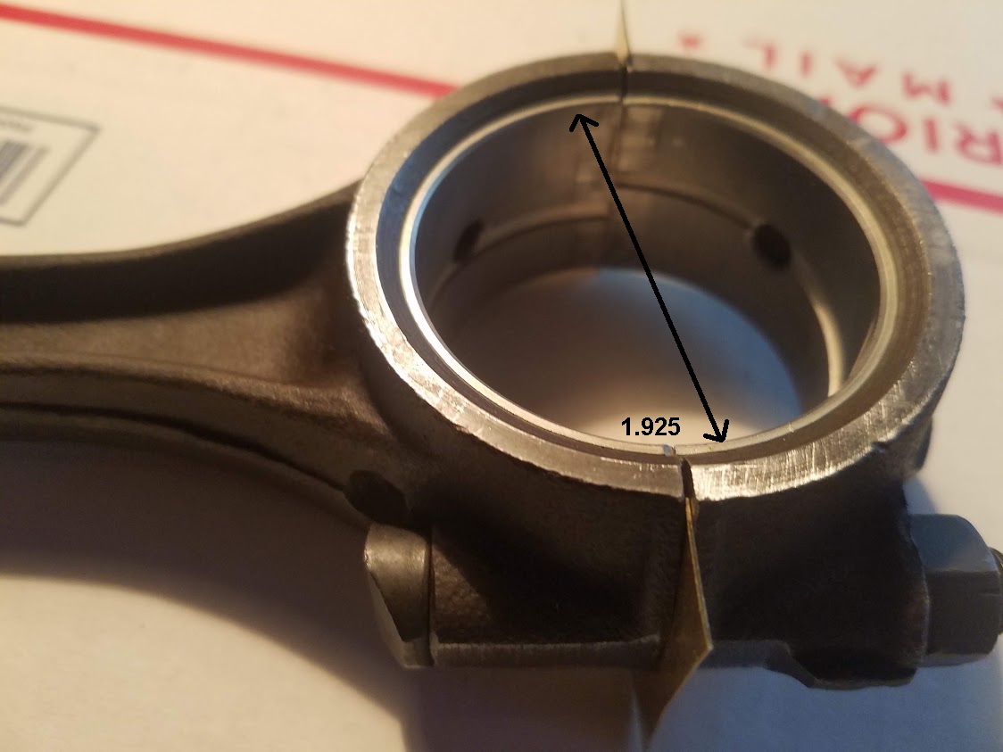
All the crankshaft journals were ground -.010. The crankshaft connecting rod journals now measure 1.927.
The connecting rod cap mounted on the rod without the bearings and no shims, has a diameter of 2.058. This dimension is the same in six places in the bore.
The new -.010 rod bearing wall thickness is .0645 x 2 = .129
2.058 - .129 = 1.929 theoretical, inside bearing diameter.
You would think that the connecting rod with the bearing diameter of 1.929 installed on the bearing journal diameter of 1.927, will allow .002 clearance on the crankshaft.
I bolted the cap on the connecting rod with the bearings, for some reason the bearing bore measures 1.925 just either side of the bearing split. When I placed the connecting rod with the bearing installed onto the crankshaft. I snugged the cap bolts and now the connecting rod moves with considerable force, if at all. I removed the cap and removed the connecting rod from the crankshaft. There are shiny wear marks on the top, and bottom halves of the bearing just above and below the split line. The bottom of the bearing radius was not touched. The connecting rod bearings are not making full radial contact. They are only making contact on the sides, where the bearing is split. I checked clearance on the notches on the side of the bearing vs the caps. There is .010 clearance. I tried to add shims where the bearing is split. The dimension remains 1.925 after shimming. I tried a piece of plastigage and got a reading of .003. The cap was only snugged down with a wrench. I am really at a loss here. I hope that I was clear. Thanks in advance |
Posted By: Lon(MN)
Date Posted: 23 Dec 2021 at 7:00am
|
I send the rods out to be resized without shims. I also get them aligned. All the rods I have sent out were egg shaped. ------------- http://lonsallischalmers.com |
Posted By: ac55tractor
Date Posted: 23 Dec 2021 at 8:25am
|
I can take care of that. Thank you very much. Merry Christmas to everyone !
|
Posted By: steve(ill)
Date Posted: 23 Dec 2021 at 8:33am
|
You said with the caps on, the bearing bore in the rod is the same in six directions.. I think that tells you the rod is OK, but i agree with Lon, the "can" get egg shaped. I think in your case what is happening is the bearing is getting "CRUSHED" at the joint between the top and bottom halfs.. Remember the discussion that the bearing shell should stick out .001 past the rod or cap so that it has a small CRUSH ? ..... I would guess you have too much.. I would check that and be temped to relieve some material at the joint so your not squeezing the bearing edges together so much. ------------- Like them all, but love the "B"s. |
Posted By: ac55tractor
Date Posted: 23 Dec 2021 at 9:09am
|
Thank you Steve (ill) for your reply, I know that I presented a lot of information in my previous post. There was something that I omitted when I posted, that was in my original notes. I carefully read what you said about having the bearing stick out .001 above the shim. I have .006 total sticking out of the bearing halves. When I first installed the rod onto the crankshaft, I used .005 shims to compensate. I was being careful not to remove too much material from the bearing face. That's when I ran into the problem with the bearing being tight on the shaft. After measuring, I ended up with 1.925 just above and below the split. I knew by adding that .006 to the diameter would cause the the bearing to appear out of round. So I placed a new bearing in a cap and set it onto the bearing journal without the connecting rod and got the same result. Where the bearing was only making contact on the sides near the split point, and was difficult to slide on the journal. I measured the width of the bearing inside that cap with a dial vernier. It reads 1.925. For some reason the bearing becomes eccentric when it is installed. I checked the thickness of the bearing with a ball mic. The thickness dimension stays consistent. |
Posted By: ac55tractor
Date Posted: 23 Dec 2021 at 10:06am
|
There is something going on with these connecting rods. The bearings were made by Federal Mogul. The mains are fine and everything lined right up with the original shims. I have been trying to figure out what is going on with the connecting rods for almost a month now. I took a lot of measurements and made a lot of notes. I am considering taking the crankshaft and the connecting rods to the guy that ground the crankshaft and ask his opinion after Christmas. If he doesn't have an answer for me, as a last resort, I was thinking about placing the bearings in the connecting rods. Allow for .001 squeeze, without shims and set the rod onto the rotary table on my milling machine, and mill the bearing to 1.929 diameter. I am looking at removing .002 Babbitt on each side. My only concern is I don't know how thick the Babbitt is.
|
Posted By: Alvin M
Date Posted: 23 Dec 2021 at 10:46am
| My machine shop line bores the block and does the rods then I don't need shims |
Posted By: steve(ill)
Date Posted: 23 Dec 2021 at 12:42pm
|
Steve, i think if you stop by and talk to the guy that machined the crank, he might have a good fix. Hopefully you dont have to do it on your milling machine.
Rather than cut a couple thousandths off the ID of the bearing, it might be a better idea to enlarge the hole in the rod so the bearings fit better. ? ------------- Like them all, but love the "B"s. |
Posted By: ac55tractor
Date Posted: 23 Dec 2021 at 1:07pm
|
Yes, I can enlarge the hole. Actually that may be a better way to go. I won't have to worry about thinning the Babbitt on the bearing. I really need a break. I have been putting a lot of thought into this since I got the crankshaft back 4 weeks ago. I wanted to be sure that I had all my ducks in a row before returning here with what I had found. I plan on seeing Jeff at the machine shop after Christmas. I have a lot of pictures to share. Is there a limit on the pictures that I can post? This has been a learning experience for me. There are a few things that I wanted to mention. The old front oil seal cut a groove in the crankshaft. By reworking the crankshaft as suggested by the forum, the oil seal will now ride on a fresh spot on the shaft. Also the dirt that came out of the coolant chamber after pulling the piston sleeves was quite a surprise. I know that this forum is the best resource for all things Allis
Chalmers tractors. I appreciate everyone's efforts in helping me out. I
will do my best to nail this down. I really don't want to assemble this
engine and end up with a bunch of parts in a basket. I have had my
Allis B for 30 years. It has been very faithful to me right up until I
pulled the engine last fall. Actually I am surprised that it ran as good
as it did with the warn crankshaft, the warn camshaft, a broken piston
ring in #3 cylinder, not to mention the leaking front and rear
crankshaft seals. Oh boy, did it smoke out of the exhaust. Kept the misquotes away for sure. Merry Christmas everyone.
|
Posted By: ac55tractor
Date Posted: 23 Dec 2021 at 4:52pm
|
You know that I wasn't going to quit until I had an answer. Now I do. There is a miss match in the bore on the connecting rod that I was using. So when I originally measured it, I got a "false" larger measurement than what was really there. The cap does not correctly match the rod. It sits off to one side. Maybe the bolts are slightly bent. I snugged the nuts down and I tapped it with a brass hammer until the bore was smooth. I remeasured the bore. It's .005 out of round. Looks like you guys had the right line of thinking. "Thank you". I am going to clean everything up, re-qualify the flats smooth, and re-cut the bores round with no shims. I will let you all know how I make out. I have been a Machinist for over 45 years. I started machining when I was 15. I Just turned 63. I'm sure that I can get it done. Thanks again Steve from Maine
|
Posted By: steve(ill)
Date Posted: 23 Dec 2021 at 6:00pm
Most do not do that due to time and cost... Being a machinist and "you need the practice"  .. eliminating the shims and boring the rods to size is an excellent idea ! .. eliminating the shims and boring the rods to size is an excellent idea !------------- Like them all, but love the "B"s. |
Posted By: steve(ill)
Date Posted: 23 Dec 2021 at 6:01pm
|
just curious... what kind of lathe / mill machine you got ? ------------- Like them all, but love the "B"s. |
Posted By: ac55tractor
Date Posted: 23 Dec 2021 at 7:22pm
|
I have a Harbor Freight Mini Mill. Some might say that it's a P.O.S.. I like it. I got it when they were passing out 30% off coupons. I hope that I am not getting carried away here with a bunch of information. I paid $575.00 for it. Regularly $799.99. I have made some serious modifications to it. I have bypassed the cheep plastic gears in the head with a quieter "V" belt drive. I have X, Y, and Z digital readouts. I added a power feed on "X" (Long feed travel). The X has 12 inches of travel. The Y has just over 4 inches of travel. I have added an air piston on the "Z" (up and down travel) and removed the useless spring lever that came with the machine. I am in the process of making a stiffener plate for the back of the machine so I can use my boring head. I have a 6 inch rotary table for it. I made an adapter plate for a 6 inch, 4 Jaw chuck, and a 6 inch, 3 jaw chuck for it. So I can make "most" , but not everything that can be made on a lathe. I have a 4 inch angle lock vice, a 3 inch Hi-Precision Toolmakers Screwless Vise. I have a full set of collets. I have a full set of drill bits and many different size endmills, carbide and high speed. I have a bunch of other tools. Too much to list. I got the machine to keep my skills sharp. I know it's just a toy, But I make good use of it. I made some rings out of aircraft grade Aluminum with Copper bar inlays for gifts. I have made all sorts of parts with it. |
Posted By: ac55tractor
Date Posted: 23 Dec 2021 at 7:40pm

|
Posted By: ac55tractor
Date Posted: 24 Dec 2021 at 10:46am
|
I found another set of connecting rods where the cap was mismatched. I numbered the piston rods as I pulled them out. I have just renumbered them. I can understand were people who do there best when working on their tractors can easily make a mistake and mismatch parts. This is not an easy process and nobody is any better than anyone else. I would have never noticed the mismatch without the support that I received here from the forum. This is an amazing resource. I feel very fortunate. |
Posted By: steve(ill)
Date Posted: 24 Dec 2021 at 12:17pm
|
YEP.... good idea to center punch the rod and cap near the bolt area prior to removal of each cap.. So, if you have the right caps on the right rods now, do the NUMBERS come out OK or do you still have to machine them ? I think factory "original" the cap was mounted to the rod and machined to size, so they have to be a "matched set". Sounds like your on the right track now !! ------------- Like them all, but love the "B"s. |
Posted By: SteveM C/IL
Date Posted: 24 Dec 2021 at 1:50pm
| Uh ,yeah, you always make sure the cap and rod are marked as a set before separation. Many already are. Older stuff not so much. |
Posted By: ac55tractor
Date Posted: 24 Dec 2021 at 2:40pm
|
Yes I have to re machine the bores. I am not an engineer, or at times the brightest bulb on the Christmas tree. There are a lot of things that I just don't understand, there has to be a reason why the bores on these rods become out of round. There is plenty of material there. I just checked them and they are all out of round at different amounts, within a few thousandths. Lon(MN) said "All the rods I have sent out were egg shaped." So it looks as if I am not the only one that have had this issue. My guess is that Steve (ill) is right, they must be mounted together and machined to size. When this is done there is no real concern for how they go together, just as long as the bore is to size and perpendicular (square) to the outside machined edges of the bore. It's really just a cost savings for the factory. I have a plan to repair the connecting rods. If anyone is interested, I will post it. I have done quite a few things at work, in the shop, and I became really resourceful. Fortunately, I have a good memory. I am not a know it all. If I don't know something, I will be the first to tell you. Steve form Maine |
Posted By: ac55tractor
Date Posted: 24 Dec 2021 at 10:26pm
|
Well, It’s Christmas eve. I have just
done some research. It seems that connecting rod and bearing bore stretching is
not uncommon. I found dozens of webpages describing how and why it happens.
Basically, it's all in the nature of an internal combustion engine. Pistons go
up and down and connecting rods, and bearing bores get stretched in the process. From what I've
found, it's been going on for over 100 years now. They say the best way to
correct a stretched connecting rod is to replace it. That leaves most of us vintage
Allis Chalmers owners in a bad place. I don't think that they are stamping out
any new connecting rods for our tractors in Milwaukee, Wisconsin or anywhere
else.:)
Okay, I know, I'm having a little fun,
and I am getting off topic here. Fortunately, I received a message from a very wise
man tonight. He said, “This isn't a Nascar engine.” He’s right. I will start a new post when I get started on reworking the connecting rods. The crankshaft end play is fixed. Merry Christmas and good night to all. Steve from Maine |
Posted By: Joe(TX)
Date Posted: 27 Dec 2021 at 2:18am
|
All the rods will be egg shaped without shims. this will allow the shim thickness to be adjusted for bearing wear. ------------- 1970 190XT, 1973 200, 1962 D-19 Diesel, 1979 7010, 1957 WD45, 1950 WD, 1961 D17, Speed Patrol, D14, All crop 66 big bin, 180 diesel, 1970 170 diesel, FP80 forklift. Gleaner A |
Posted By: ac55tractor
Date Posted: 27 Dec 2021 at 7:07pm
|
I do not disagree with you. I approached this with an open mind today. After a lot of measuring, it seems that no matter what I do, I cannot increase the distance shown with the arrow in the picture. This distance remains at 1.925. I can add as much sim as I want, and it still won't increase the 1.925 distance across. All the bearing journals on the crank shaft have been ground down to 1.927 or -.010 from the original dimensions. When I hand tighten the rod nuts to any of the rods, with
any combination of bearing, and matched shims to any of the journals on the
crank shaft, the area above and below the mating edges of the bearing will only
make contact and rub in the area shown in the picture. If I "snug"
the connecting rod to the crankshaft with a wrench, the rod will not move.
Please feel free to ask any questions. I want to get to the bottom of this
before I cut the bearing bores to fit the new bearings. Respectfully Steve |
Posted By: steve(ill)
Date Posted: 27 Dec 2021 at 7:45pm
|
I dont think anyone disagrees with your analysis... You need a couple thousandths clearance between the bearings and crank.. No matter how many SHIMS you add, you are not going to increase the horizontal dimension of the bearing.... Remachine is the only way.
How it got "TOO SMALL" is unknown at this point.. I did not look up the "factory" dimensions of the rod or crank to verify numbers... At this point it dont matter. ------------- Like them all, but love the "B"s. |
Posted By: ac55tractor
Date Posted: 27 Dec 2021 at 8:04pm
|
No worry''s, I have all the hard copy manuals. Thanks for everything .
|
Posted By: SteveM C/IL
Date Posted: 27 Dec 2021 at 11:18pm
| Around here rods are sent to the machine shop where they torque em down and hone the bore round. I don't think they generally have to remove any material at parting line. I'm no expert on this but that is my understanding. |
Posted By: ac55tractor
Date Posted: 28 Jan 2022 at 12:03pm
I have been very ill. It's not covid. Going for tests next week. Overhaul on hold for over a week now. I wanted to take the time to say thanks to Steve (ill) for the heads up with my crankshaft gear and the rework that can be done. When I sent the crankshaft out, the guy who ground it assumed that the thrust bearing width was 1.625. So he machined a gap to 1.630. Come to find out, the thrust bearing was 1.620. That will give me .010 shaft end play. Instead of bringing the crank back to him, I am going to undercut the gear .005 - .007 and install the gear and call it good. Thanks again Steve(ill) Steve (inME)
|
") steve(ill) wrote:
steve(ill) wrote:Posted By: DrAllis
Date Posted: 28 Jan 2022 at 12:14pm
| .010" crank endplay ?? I wouldn't lose one seconds sleep over that. Run it. |
Posted By: ac55tractor
Date Posted: 28 Jan 2022 at 12:19pm
|
Thanks, DrAllis One less thing to worry about, :) Steve (inME)
|
Posted By: SteveM C/IL
Date Posted: 28 Jan 2022 at 9:27pm
| Take the time out to get your health back. Without that,nothing else matters much. |
Posted By: ac55tractor
Date Posted: 29 Jan 2022 at 10:56am
|
Thanks SteveM C/IL for your kind advice. I realize that the forum is not really the place for medical issues. All points are leading to what is called diverticula. You can Google it. I am feeling a little better this morning. I have some things that I want to pass along on the "Connecting rod "rework" page. I will try to post over there later on today or tomorrow. Sending my best to everyone at the Allis Chalmers forum. Steve (inME) |
Posted By: ac55tractor
Date Posted: 19 May 2022 at 8:43pm
|
Hi Everyone. I just wanted to say how grateful I am
to the forum, to Steve(ill), Paul B, Steve M C/IL, and all the others. I
feel that their guidance is paying off. After my crankshaft was reground, roughly .040 was removed and cleaned up from the “thrust area” that had warn off,
on crankshaft. After applying blue to the front seal journal. and with the front seal installed, I aligned the plate on the front of the engine and spun the crankshaft. From what I
can see, the seal is riding on a clean un-warn area of the seal journal. In the end the rework has appeared to have moved the
crankshaft forward making a new contact area for the front seal to ride. Or, is an easy sleeve still going to be needed here? Thanks Steve  |
Posted By: DrAllis
Date Posted: 19 May 2022 at 8:49pm
| Only reason for a speedi-repair sleeve is to cover up worn in groove on a shaft. You've moved the groove out of the path of wear. Why would you need it ?? |
Posted By: ac55tractor
Date Posted: 19 May 2022 at 9:08pm
|
Thanks for your reply DrAllis. I have never heard of an easy sleeve until
just recently. Most of this is new to me. I really have struggled through a lot of this rebuild. I really just want this to be a one and done. I'm sure that you can
understand. Steve
|
Posted By: steve(ill)
Date Posted: 19 May 2022 at 9:49pm
|
I would agree, no sleeve... the big question is WHY did the crank move that much ? It looks like a quarter inch ? ------------- Like them all, but love the "B"s. |
Posted By: ac55tractor
Date Posted: 19 May 2022 at 10:00pm
|
Steve Can you please look at the start of this post and I am sure it will all came back to you. Thanks Steve (in-ME)
|
Posted By: steve(ill)
Date Posted: 19 May 2022 at 10:51pm
|
Steve, i thought you had the face machined and the gear pushed on .037 inch to get the bearing thrust clearance back to spec... I can see the "groove" moving 30 thousands, but doubt you could see that... The photo looks like it move 1/4 inch , unless i am looking at the groove wrong ?? ......... I would be more inclined to believe the seal is setting different in the housing, or the seal is "different" than original ?
I dont think there is room in the block to move the crank 1/4 inch and still get the connecting rods installed ? ------------- Like them all, but love the "B"s. |
Posted By: ac55tractor
Date Posted: 20 May 2022 at 2:02pm
|
Steve Maybe this will help. It was hard to get this
picture with my phone, but I'm sure you get the idea. I used a
Machinist's scale, from Starrett. Each line is .010. It shows roughly .040 from the old ware groove to the end of the blue. I only blued where
the old seal was up to the crank gear to check for seal contact. You are right, the
front seal that came with the gasket kit is not at all like the
original. The contact area on the new seal is also roughly .032. After some searching this morning the seal is for D10, D12, D14, D15 Allis. It does seem to fit the application without any interference from the lower belt pulley. All of the other gaskets from the kit fit just fine. The gasket kit was for a B so I got it. There were some extra gaskets with the kit that I didn't recognize, but the ones that I needed were included. I am not using the head gasket from that kit. It's marked China. I have a Fel-Pro head gasket kit Part # HS-7378B that I will be using. There was another thin front lip seal that came with the kit, it was larger in diameter than the original. I did come across some postings where some guys were using J.B. Weld. I just didn't know what would be best in this case. As always, Thanks Steve (inME)  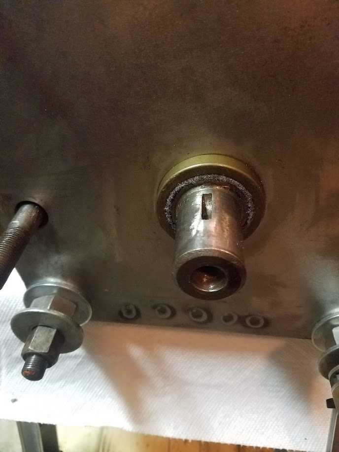
|