| Author |
 Topic Search Topic Search  Topic Options Topic Options
|
Jim-Ohio 
Orange Level


Joined: 13 Sep 2009
Location: Cols.Grove,Ohio
Points: 335
|
 Post Options Post Options
 Thanks(0) Thanks(0)
 Quote Quote  Reply Reply
 Topic: Lift Latch Brace Topic: Lift Latch Brace
Posted: 16 Mar 2012 at 4:18pm |
|
Could someone post pictures and dimensions so that I could make the brace that goes between the lift latches that I just bought for a D-17. Thanks. Jim
|
|
'61D17, '51WD, '51CA, '41C, '49C, Woods 5'&6'Mower, 6'Blade, CA-Plow, CA-Cultivator, 3-Btm snap-coupler plow, 4-row planter, WD 4-row cultivator, 80R mower,#7 mower,B/C mower
|
 |
|
Sponsored Links
|
|
 |
BobHnwO 
Orange Level


Joined: 16 Sep 2009
Location: Jenera Ohio
Points: 693
|
 Post Options Post Options
 Thanks(0) Thanks(0)
 Quote Quote  Reply Reply
 Posted: 16 Mar 2012 at 5:26pm Posted: 16 Mar 2012 at 5:26pm |
|
Mine measures 1 1/4"X32",prolly could use black iron pipe.
|
|
Why do today what you can put off til tomorrow.
|
 |
Dave (NE) 
Orange Level

Joined: 12 Sep 2009
Location: Eagle Nebraska
Points: 2154
|
 Post Options Post Options
 Thanks(0) Thanks(0)
 Quote Quote  Reply Reply
 Posted: 16 Mar 2012 at 8:21pm Posted: 16 Mar 2012 at 8:21pm |
|
unsure what you mean by brace. if you are talking about the pipe that goes horizonal between them, yes, I could get a picture.
|
 |
tony 
Silver Level


Joined: 17 Oct 2011
Location: deper wi
Points: 76
|
 Post Options Post Options
 Thanks(0) Thanks(0)
 Quote Quote  Reply Reply
 Posted: 16 Mar 2012 at 9:16pm Posted: 16 Mar 2012 at 9:16pm |
|
Not to hijack the post but what's the brace for?
|
 |
RichinWis 
Orange Level


Joined: 11 Sep 2009
Location: Deforest Wis
Points: 691
|
 Post Options Post Options
 Thanks(0) Thanks(0)
 Quote Quote  Reply Reply
 Posted: 16 Mar 2012 at 9:20pm Posted: 16 Mar 2012 at 9:20pm |
|
That brace is a solid shaft, not a piece of pipe, and they still got bent.
|
 |
Jim-Ohio 
Orange Level


Joined: 13 Sep 2009
Location: Cols.Grove,Ohio
Points: 335
|
 Post Options Post Options
 Thanks(0) Thanks(0)
 Quote Quote  Reply Reply
 Posted: 16 Mar 2012 at 9:33pm Posted: 16 Mar 2012 at 9:33pm |
|
Yes, I'm talking about the horizontal shaft that goes between the lift latches. I'd like to see a picture of one to see how it fastens to the lift latches.
|
|
'61D17, '51WD, '51CA, '41C, '49C, Woods 5'&6'Mower, 6'Blade, CA-Plow, CA-Cultivator, 3-Btm snap-coupler plow, 4-row planter, WD 4-row cultivator, 80R mower,#7 mower,B/C mower
|
 |
RichinWis 
Orange Level


Joined: 11 Sep 2009
Location: Deforest Wis
Points: 691
|
 Post Options Post Options
 Thanks(0) Thanks(0)
 Quote Quote  Reply Reply
 Posted: 16 Mar 2012 at 9:37pm Posted: 16 Mar 2012 at 9:37pm |
|
It has bolts through it and through the latches
|
 |
jiminnd 
Orange Level

Joined: 16 Sep 2009
Location: Rutland ND
Points: 2297
|
 Post Options Post Options
 Thanks(0) Thanks(0)
 Quote Quote  Reply Reply
 Posted: 16 Mar 2012 at 9:44pm Posted: 16 Mar 2012 at 9:44pm |
|
I think mine had roll pins thru it, be a few years since I removed one.
|
 |
Jim-Ohio 
Orange Level


Joined: 13 Sep 2009
Location: Cols.Grove,Ohio
Points: 335
|
 Post Options Post Options
 Thanks(0) Thanks(0)
 Quote Quote  Reply Reply
 Posted: 17 Mar 2012 at 7:21am Posted: 17 Mar 2012 at 7:21am |
|
Could someone give me the measurement between the center of the holes in the rod for mounting to the latches? A picture of one would still help me to get it made right. Thanks
Edited by Jim-Ohio - 17 Mar 2012 at 7:23am
|
|
'61D17, '51WD, '51CA, '41C, '49C, Woods 5'&6'Mower, 6'Blade, CA-Plow, CA-Cultivator, 3-Btm snap-coupler plow, 4-row planter, WD 4-row cultivator, 80R mower,#7 mower,B/C mower
|
 |
BobHnwO 
Orange Level


Joined: 16 Sep 2009
Location: Jenera Ohio
Points: 693
|
 Post Options Post Options
 Thanks(0) Thanks(0)
 Quote Quote  Reply Reply
 Posted: 17 Mar 2012 at 7:29am Posted: 17 Mar 2012 at 7:29am |
|
I don't have a bar on mine but it should be 30" center to center on holes.
|
|
Why do today what you can put off til tomorrow.
|
 |
Gary 
Orange Level Access

Joined: 13 Sep 2009
Location: Peterborough,On
Points: 5899
|
 Post Options Post Options
 Thanks(0) Thanks(0)
 Quote Quote  Reply Reply
 Posted: 17 Mar 2012 at 7:34am Posted: 17 Mar 2012 at 7:34am |
I would think one drift pin or bolt would be sufficient to hold the crossshaft in place. Your lift arms may have got bent slightly sometime over the last 50+ years, therefore the distance between the holes would be different. OR just drill one hole, then install the brace and 'mark and drill' the other hole. Gary
|
 |
CTuckerNWIL 
Orange Level


Joined: 11 Sep 2009
Location: NW Illinois
Points: 22825
|
 Post Options Post Options
 Thanks(0) Thanks(0)
 Quote Quote  Reply Reply
 Posted: 17 Mar 2012 at 8:04am Posted: 17 Mar 2012 at 8:04am |
|
Take a tape measure and measure between the holes. Best do like Gary said and drill and pin one before you mark the other. It doesn't take much of a twist in either arm to make that center distance change.
|
|
|
 |
Jim-Ohio 
Orange Level


Joined: 13 Sep 2009
Location: Cols.Grove,Ohio
Points: 335
|
 Post Options Post Options
 Thanks(0) Thanks(0)
 Quote Quote  Reply Reply
 Posted: 17 Mar 2012 at 1:05pm Posted: 17 Mar 2012 at 1:05pm |
|
Thanks for the info. I'll get a rod and just drill the hole on one end until I get out to my son's in Iowa where the tractor is. Jim
|
|
'61D17, '51WD, '51CA, '41C, '49C, Woods 5'&6'Mower, 6'Blade, CA-Plow, CA-Cultivator, 3-Btm snap-coupler plow, 4-row planter, WD 4-row cultivator, 80R mower,#7 mower,B/C mower
|
 |
AC WD45 
Orange Level


Joined: 28 Sep 2009
Location: Mid Michigan
Points: 2060
|
 Post Options Post Options
 Thanks(0) Thanks(0)
 Quote Quote  Reply Reply
 Posted: 17 Mar 2012 at 1:32pm Posted: 17 Mar 2012 at 1:32pm |
|
Once again, what were they for?
|
|
German Shepherd dad
1957 Allis Chalmers WD45
#WD234847
1951 Allis Chalmers WD
#WD88193
|
 |
Ted J 
Orange Level


Joined: 05 Jul 2010
Location: La Crosse, WI
Points: 18943
|
 Post Options Post Options
 Thanks(0) Thanks(0)
 Quote Quote  Reply Reply
 Posted: 17 Mar 2012 at 1:55pm Posted: 17 Mar 2012 at 1:55pm |
|
They were primarily to keep the lift arms from twisting and thus breaking from stress. I would bolt one side and then (I would use a Hi-Lift jack) push the other side out to the 30" (If that is correct). And I wouldn't push it a lot if it is bent in that far either. Gotta use some common sense on that part. They really help on heavy loads, such as a big disk and plowing. That's where they tend to get bent.
|
|
"Allis-Express"
19?? WC / 1941 C / 1952 CA / 1956 WD45 / 1957 WD45 / 1958 D-17
|
 |
Dave (NE) 
Orange Level

Joined: 12 Sep 2009
Location: Eagle Nebraska
Points: 2154
|
 Post Options Post Options
 Thanks(0) Thanks(0)
 Quote Quote  Reply Reply
 Posted: 17 Mar 2012 at 6:26pm Posted: 17 Mar 2012 at 6:26pm |
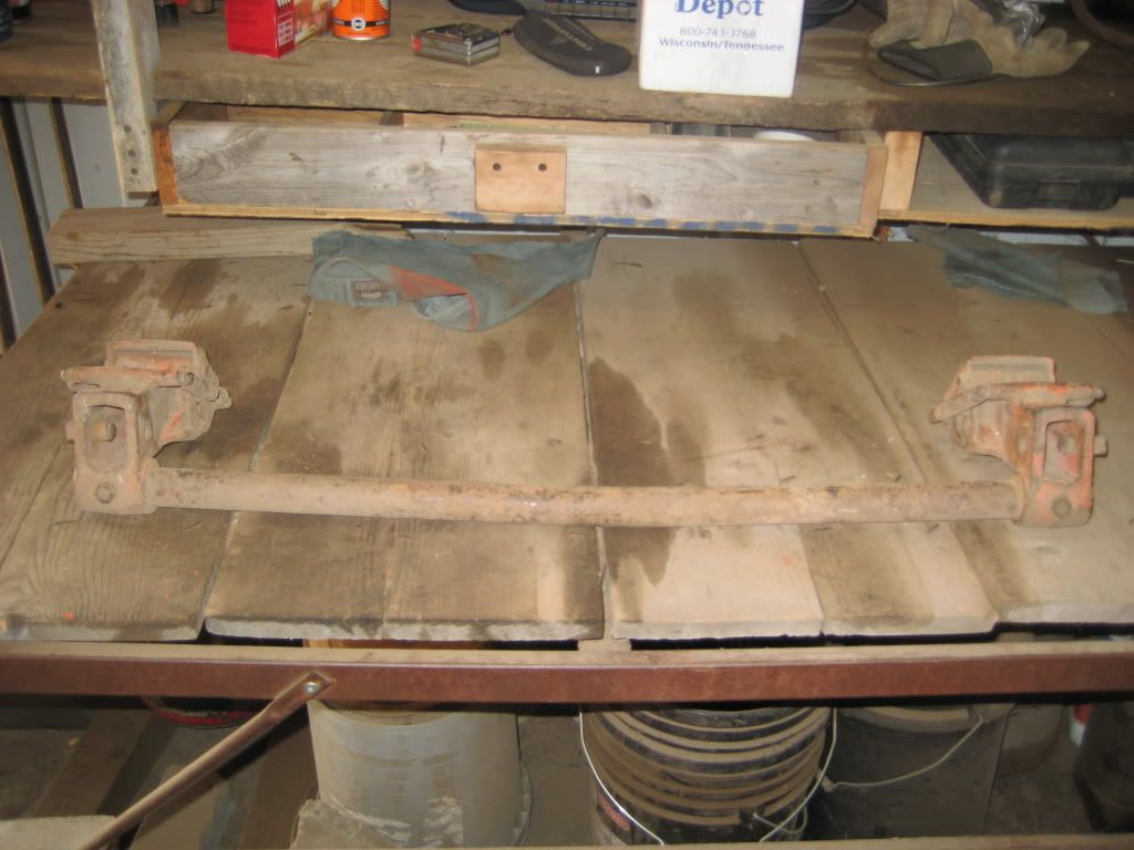
Here are some pictures I took. Hope this helps. The bar is solid. It measured 32 3/8" from outside to outside. As I understand it, the purpose is so the equipment does not put so much side to side pressure on the lift arms that the lift arms break. Someone correct me if I'm wrong or provide a more complete explanation.
|
 |
Jim-Ohio 
Orange Level


Joined: 13 Sep 2009
Location: Cols.Grove,Ohio
Points: 335
|
 Post Options Post Options
 Thanks(0) Thanks(0)
 Quote Quote  Reply Reply
 Posted: 17 Mar 2012 at 6:50pm Posted: 17 Mar 2012 at 6:50pm |
|
Dave, Thanks for the pictures, helps a lot. Jim
|
|
'61D17, '51WD, '51CA, '41C, '49C, Woods 5'&6'Mower, 6'Blade, CA-Plow, CA-Cultivator, 3-Btm snap-coupler plow, 4-row planter, WD 4-row cultivator, 80R mower,#7 mower,B/C mower
|
 |


 Topic Options

 Post Options
 Thanks(0)


