This site is not affiliated with AGCO Inc., Duluth GA., Allis-Chalmers Co., Milwaukee, WI., or any surviving or related corporate entity. All trademarks remain the property of their respective owners. All information presented herein should be considered the result of an un-moderated public forum with no responsibility for its accuracy or usability assumed by the users and sponsors of this site or any corporate entity.
The Forum Parts and Services Unofficial Allis Store Tractor Shows Serial Numbers History
Forum Home Forum Home > Allis Chalmers > Construction and other equipment
  New Posts New Posts
  FAQ FAQ  Forum Search   Events   Register Register  Login Login


H4 BRAKE ASSEMBLY PHOTOS

 Post Reply Post Reply
Author
Message
pinball View Drop Down
Orange Level Access
Orange Level Access


Joined: 28 May 2014
Location: missouriu
Points: 6355
Post Options Post Options   Thanks (0) Thanks(0)   Quote pinball Quote  Post ReplyReply Direct Link To This Post Topic: H4 BRAKE ASSEMBLY PHOTOS
    Posted: 23 Aug 2014 at 9:46am
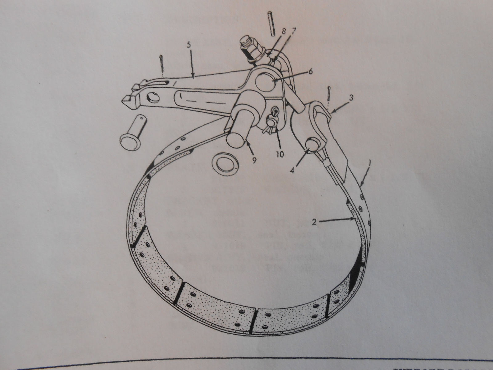
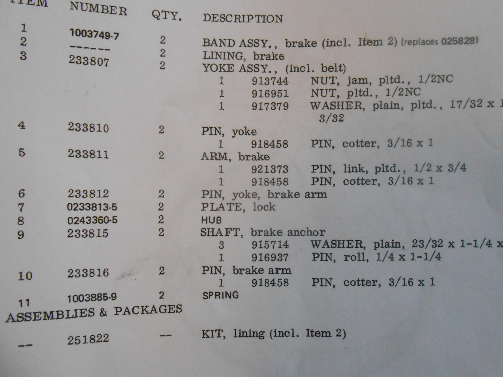
Here are the photos of the parts manual for the brake assembly on an allis H4 crawler. I am trying to remove the shaft that holds the pivot in place. On the parts page it lists two shafts for the pivot arm. is this correct. I am trying to get the brake assembly loose so I can remove it with the steering clutch. When I hit the end of the shaft it sounds like metal on metal. roll pin has been removed. surely some one on here has removed this assembly and can tell me if theres a trick to getting it out or am I just missing something. thanks
Back to Top
Sponsored Links


Back to Top
Randaleky View Drop Down
Silver Level
Silver Level
Avatar

Joined: 17 Aug 2011
Location: belfry, ky.
Points: 427
Post Options Post Options   Thanks (0) Thanks(0)   Quote Randaleky Quote  Post ReplyReply Direct Link To This Post Posted: 23 Aug 2014 at 11:08am
NO. 9 IS THE ONLY PIN TO REMOVE AFTER THE ROLL PIN. DID YOU SEE ANYTHING ON THE BACK SIDE OF WHERE PIN SHOULD COME THROUGH TOWARD THE REAR END AREA ? MAY TRY TO LOOSEN THE TWO BOLTS ON OUTER SIDE TO LIFT THE FRAME UP 1/2 INCH TO ALLOW YOU TO TRY AND PUSH THE PIN OUT THE TRACK SIDE.
Back to Top
CTuckerNWIL View Drop Down
Orange Level
Orange Level
Avatar

Joined: 11 Sep 2009
Location: NW Illinois
Points: 22824
Post Options Post Options   Thanks (0) Thanks(0)   Quote CTuckerNWIL Quote  Post ReplyReply Direct Link To This Post Posted: 23 Aug 2014 at 11:16am
Is it possible there is a step worn in that pin that is hanging it up? maybe loosen the adjustment nut on top all the way so you can wiggle things around?
http://www.ae-ta.com
Lena 1935 WC12xxx, Willie 1951 CA6xx Dad bought new, 1954WD45 PS, 1960 D17 NF
Back to Top
Bud(WI) View Drop Down
Bronze Level
Bronze Level


Joined: 12 Sep 2009
Location: Wisconsin
Points: 68
Post Options Post Options   Thanks (0) Thanks(0)   Quote Bud(WI) Quote  Post ReplyReply Direct Link To This Post Posted: 23 Aug 2014 at 6:55pm
I've had them come out with a hammer and punch and not come out even with heat and a 12 ton jack pushing on them. I think that one I finally used a hack saw on the pin after ruining the brake arm. These were on an H3, which is almost identical to the H4 on those parts. Luckily I was trying to make one working machine out of two, so getting three out of four apart in one piece was good enough. 
Back to Top
albatros_3 View Drop Down
Silver Level
Silver Level


Joined: 16 Apr 2012
Location: SE Michigan
Points: 450
Post Options Post Options   Thanks (0) Thanks(0)   Quote albatros_3 Quote  Post ReplyReply Direct Link To This Post Posted: 25 Aug 2014 at 7:48am
On my 653, it took a lot of heat, PB Blaster, and hammering. I hit them from both sides, once they start to move, you got them licked. 
Back to Top
 Post Reply Post Reply
  Share Topic   

Forum Jump Forum Permissions View Drop Down

Forum Software by Web Wiz Forums® version 11.10
Copyright ©2001-2017 Web Wiz Ltd.

This page was generated in 0.109 seconds.


Help Support the
Unofficial Allis Forum