| Author |
 Topic Search Topic Search  Topic Options Topic Options
|
bobkyllo 
Orange Level


Joined: 14 Sep 2009
Location: minnesota
Points: 1506
|
 Post Options Post Options
") Thanks(0) Thanks(0)
 Quote Quote  Reply Reply
 Topic: Dixon mower wiring Topic: Dixon mower wiring
Posted: 29 Nov 2020 at 11:57pm |
|
So I traded some labor for a Dixon zero turn mower with no motor. It originally had a 10 horse Briggs on it.
Well I found a 14.5 horse Briggs I/c motor. I've got it mounted and it's just about ready to start.
My problem is the wiring. My motor has 2 wires coming from under the engine shroud. I'm guessing they have something to do with the charging? Although I do not see a voltage regulator.
Any way I would guess the red wire is the positive and needs to be fed back into the battery. The other wire is a ground?
The Dixon wiring seems pretty straight forward. I've got one plus that needs attention. It is a 2 wire plug. It has a red wire that is connected to the starter selenoid battery terminal and the other end goes? I'm guessing it goes to the red wire coming from under the shroud?
The second wire in that plug is green. Looks like one end goes to the key switch and the other end appears like it was screwed to the motor for a grind of some sort. I'm guessing that's how they killed the spark.
|
 |
|
Sponsored Links
|
|
|
jaybmiller
Orange Level Access
Joined: 12 Sep 2009
Location: Greensville,Ont
Points: 21464
|
Post Options
Thanks(0)
Quote Reply
Posted: 30 Nov 2020 at 5:44am |
High probability.... The B&S wiring//
If the two wires are in ONE connector.....
Red wire is +12V for charging battery(there's a diode in the heatshrink)
Gry wire needs +12 to power the 'anti-dieseling' solenoid on the btm of carb. The problem I have is what shuts OFF the engine? If there's NO A-D solenoid, the 2nd wire should be the Mag kill wire.
Post the 'model/type/code' info from the tag..3 groups of numbers.. that'll help. or a picture....
You might find a Dixon mower wiring diagram online ?? If you put an ohmeter between the grn wire and ground, turing the key off-on, should confirm if the key shorts the grn wire to ground when off, open when 'run/start'.
Jay
Edited by jaybmiller - 30 Nov 2020 at 5:56am
|
|
3 D-14s,A-C forklift, B-112
Kubota BX23S lil' TOOT( The Other Orange Tractor)
Never burn your bridges, unless you can walk on water
|
|
ac fleet
Orange Level
Joined: 12 Jan 2014
Location: Arrowsmith, ILL
Points: 2204
|
Post Options
Thanks(0)
Quote Reply
Posted: 30 Nov 2020 at 5:59pm |
|
I had the diagram somewhere,--cant find it now but its on the internet. Dixon has a very funky way of wiring the mowers. got 3 of them here---all junk -- cant get the cone drive to work on the left side. --- biggest POS mower ever made! lol!
|
|
http://machinebuildersnetwork.com/
|
|
steve(ill)
Orange Level Access
Joined: 11 Sep 2009
Location: illinois
Points: 77715
|
Post Options
Thanks(0)
Quote Reply
Posted: 30 Nov 2020 at 6:22pm |
|
|
|
Like them all, but love the "B"s.
|
|
steve(ill)
Orange Level Access
Joined: 11 Sep 2009
Location: illinois
Points: 77715
|
Post Options
Thanks(0)
Quote Reply
Posted: 30 Nov 2020 at 6:32pm |
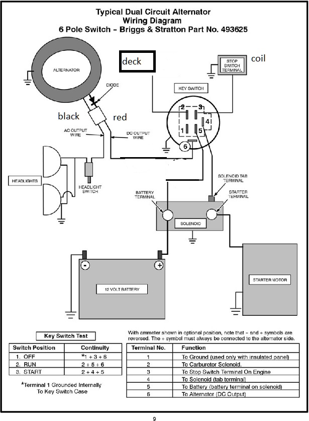
if your "two wires" have nothing to do with the ignition system, then they are CHARGING.. Do you have a STARTER MOTOR ? IF so, it probably needs a charge system.. This is "generic".... but follow the red and black wire from the alternator.

drawing below is a little harder to comprehend --- but shows the RED wire has the diode and goes to the BATTERY thru the amp meter and switch.
Edited by steve(ill) - 30 Nov 2020 at 6:53pm
|
|
Like them all, but love the "B"s.
|
|
shameless dude
Orange Level

Joined: 10 Apr 2017
Location: east NE
Points: 13611
|
Post Options
Thanks(0)
Quote Reply
Posted: 30 Nov 2020 at 8:00pm |
|
don't forget all them safety sensor wires! LMAO
|
|
bobkyllo
Orange Level
Joined: 14 Sep 2009
Location: minnesota
Points: 1506
|
Post Options
Thanks(0)
Quote Reply
Posted: 01 Dec 2020 at 12:19pm |
|
Yes I've got a starter and an electric deck engagement clutch.
I'm certain atleast one of the wires under the shroud is for the charging. I'm guessing it's the red one with the shrink tube on it. But the extra wire? Perhaps it has to do with the ignition?
How are we going to regulate the voltage is being made?
I have no amp meter. This mower is fairly straight forward. Key switch to start it, headlight switch, and deck switch. No guages of any sort.
|
|
steve(ill)
Orange Level Access
Joined: 11 Sep 2009
Location: illinois
Points: 77715
|
Post Options
Thanks(0)
Quote Reply
Posted: 01 Dec 2020 at 12:42pm |
Look at the drawing below.. The RED wire with the shrink wrap has a one way DIODE in it so it puts out a DC voltage to charge the battery.. that is terminal #6 on the key.. It is such a low current that it does not need REGULATED ( trickle charge). The KEY turns it on to the battery.. That keeps it from being connected when the motor is not running ( key off). The black wire goes to the headlight switch.. Headlights dont work unless the tractor is RUNNING.
the MOTOR KILL WIRE from the coil goes to terminal #3 on the switch.. Grounds it out when key is OFF.
The deck could run off terminal #2 on the key.
Edited by steve(ill) - 01 Dec 2020 at 1:01pm
|
|
Like them all, but love the "B"s.
|
|
ac fleet
Orange Level
Joined: 12 Jan 2014
Location: Arrowsmith, ILL
Points: 2204
|
Post Options
Thanks(0)
Quote Reply
Posted: 03 Dec 2020 at 9:43am |
Your ignition has nothing to do with the alternator circuit --- ignition comes from the module on the outside of the flywheel and is NOT connected to alternator or battery in any way. ---- it only connects to the key switch as a kill wire and will run without being hooked up, but you would have to pull plug wire off to shut motor off.
Alternator is extra and engine would run without one on it IF you had a recoil to start it which you dont ---- they are electric start only on these.
|
|
http://machinebuildersnetwork.com/
|
|