| Author |
 Topic Search Topic Search  Topic Options Topic Options
|
Hardtimes 
Bronze Level

Joined: 19 Sep 2020
Location: Oklahoma
Points: 9
|
 Post Options Post Options
") Thanks(0) Thanks(0)
 Quote Quote  Reply Reply
 Topic: AC 170 Hydraulics Topic: AC 170 Hydraulics
Posted: 19 Sep 2020 at 5:14pm |
Hi I'm new here. I bought a 170 gas a few months ago and the hydraulics have always built pressure. I have to run it with the dipstick unscrewed to relieve the pressure. I assume it should be vented, but somebody previous has modified the dip stick. What should the dipstick look like? 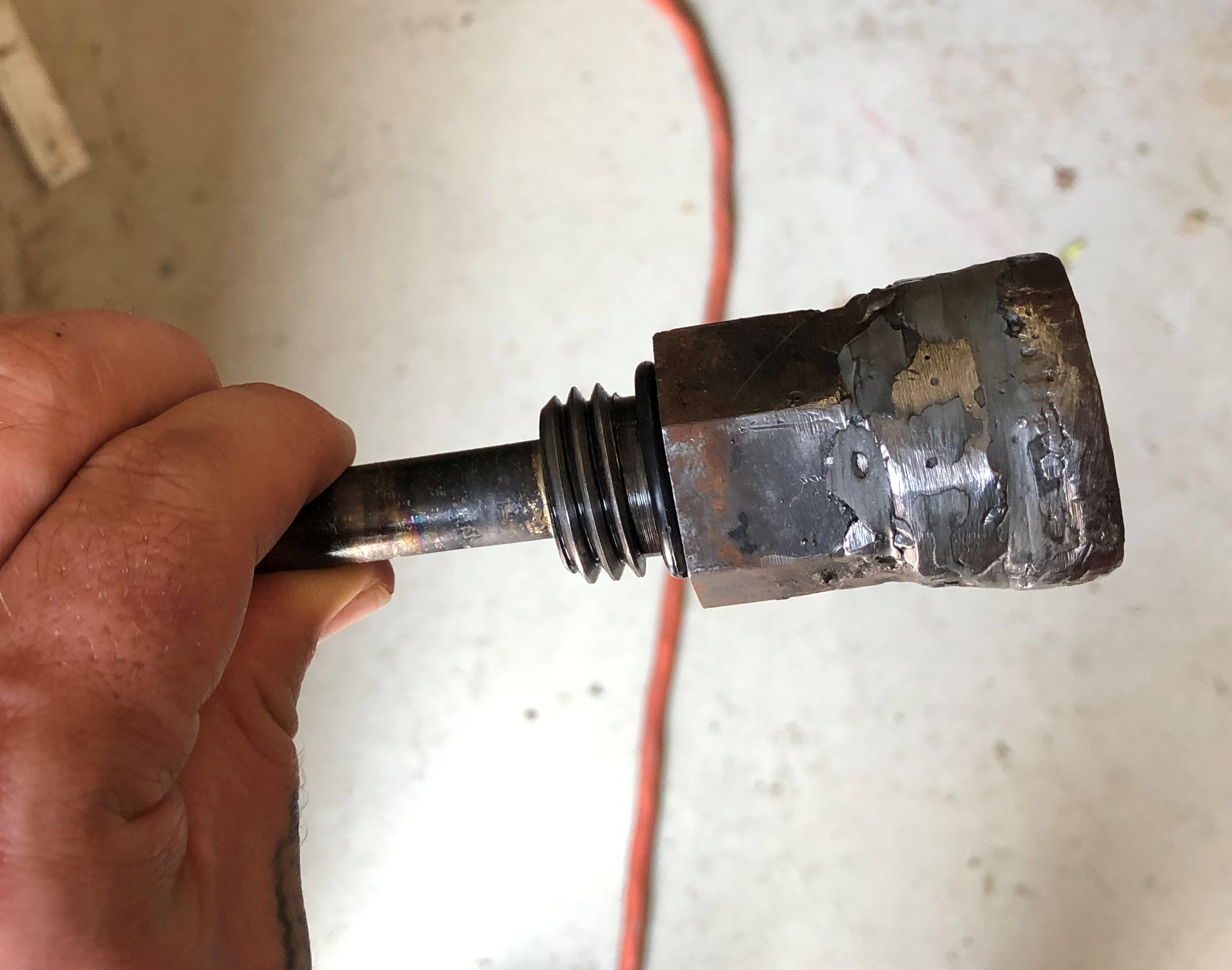
Edited by Hardtimes - 19 Sep 2020 at 5:19pm
|
 |
|
Sponsored Links
|
|
|
Boss Man
Orange Level

Joined: 03 Mar 2018
Location: Greenleaf, WI
Points: 608
|
Post Options
Thanks(0)
Quote Reply
Posted: 19 Sep 2020 at 6:07pm |
|
yes the welded the vent cap in place. time to call a salvage yard for a different one.
|
|
DrAllis
Orange Level Access
Joined: 12 Sep 2009
Points: 19477
|
Post Options
Thanks(0)
Quote Reply
Posted: 19 Sep 2020 at 7:44pm |
|
When you get a good dipstick, pull the cotter pin and drop out the round ball inside the tube and throw it away. Make sure the steel wool inside the top is clean and free to actually breathe in and out.
|
|
Hardtimes
Bronze Level
Joined: 19 Sep 2020
Location: Oklahoma
Points: 9
|
Post Options
Thanks(0)
Quote Reply
Posted: 20 Sep 2020 at 2:19pm |
Thank you for the responses! Any suggestions on where to get a dipstick? I also have question about the hydraulics. The tractor has a Westendorf loader on it and when they installed it they ran the line from the center of the pump to the valves. Then from the return on the valves to the line that feeds the rear remote ports. So my question is, Is this right or how should it be installed? When I use a backhoe attachment on it, It pushes Hydraulic fluid past the seals on the valves.  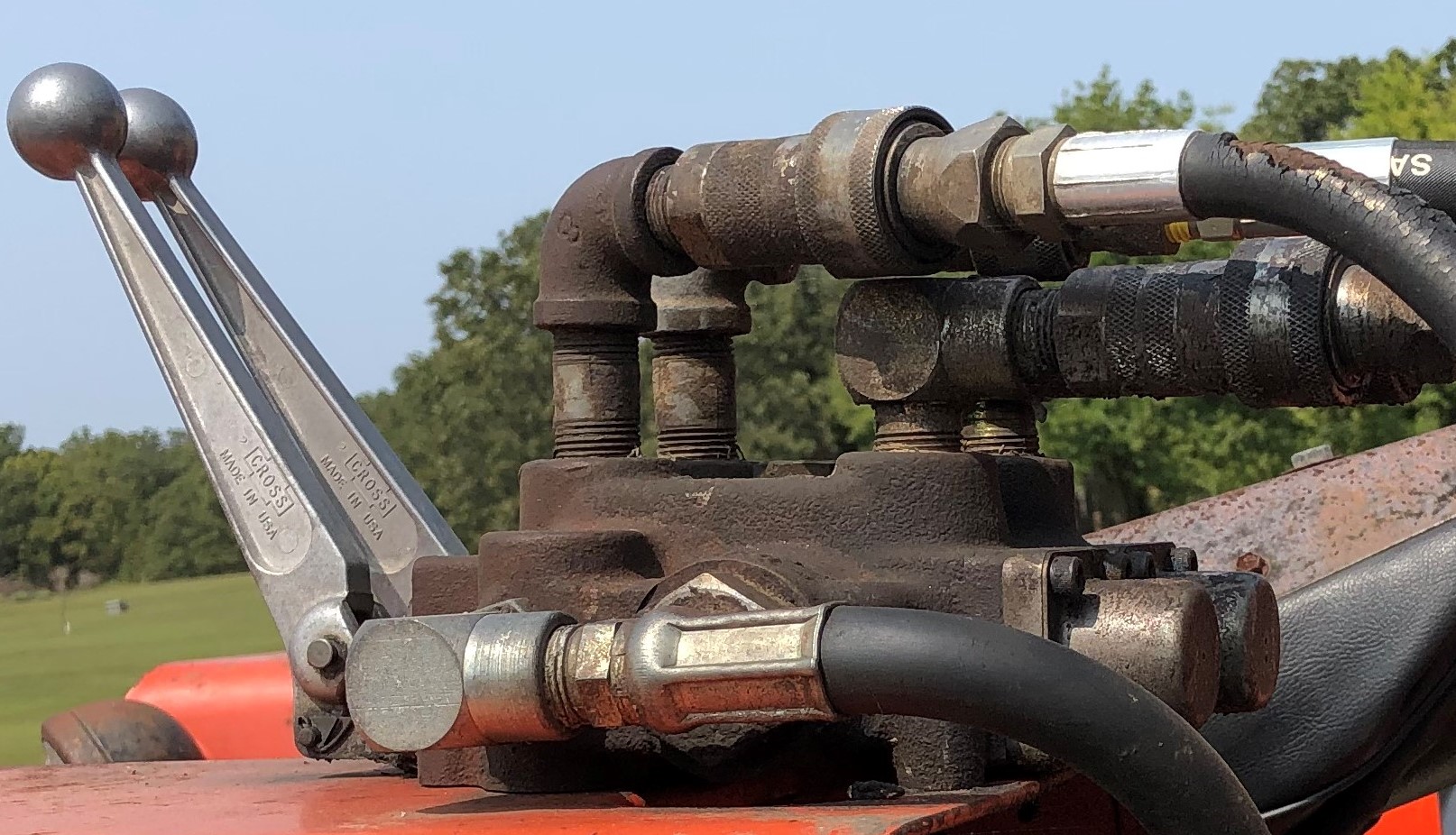
|
|
DougG
Orange Level
Joined: 20 Sep 2009
Location: Mo
Points: 7943
|
Post Options
Thanks(0)
Quote Reply
Posted: 20 Sep 2020 at 2:54pm |
|
good luck as most advise is questionable,,
Edited by DougG - 20 Sep 2020 at 4:58pm
|
|
DrAllis
Orange Level Access
Joined: 12 Sep 2009
Points: 19477
|
Post Options
Thanks(0)
Quote Reply
Posted: 20 Sep 2020 at 4:46pm |
|
To do it like it seems to be plumbed, you need a "Power Beyond" open center valve on the loader. It would receive oil from the pump and then send it on to the tractors hydraulic valve stack. This Power Beyond valve would have a third hose, which needs to go to sump, to relieve any back pressure on the spool seals. How your backhoe is plumbed I have no idea, but I assume it's wrong. Dipstick should be readily available from a D17 S3 and S4 or any 170/175. I could use a dipstick from a 180-185-190-190XT too but the full mark could be a little different, which could easily be re-marked.
|
|
Joe(TX)
Orange Level

Joined: 11 Sep 2009
Location: Weatherford. TX
Points: 1682
|
Post Options
Thanks(0)
Quote Reply
Posted: 20 Sep 2020 at 6:30pm |
Dr Allis is right. The valve does not appear to have a power beyond plug, There should be another line connecting from the other plug on the end of the valve connecting to the sump. Teeing into the return line from the remote line will work.
Edited by Joe(TX) - 20 Sep 2020 at 6:37pm
|
|
1970 190XT, 1973 200, 1962 D-19 Diesel, 1979 7010, 1957 WD45, 1950 WD, 1961 D17, Speed Patrol, D14, All crop 66 big bin, 180 diesel, 1970 170 diesel, FP80 forklift. Gleaner A
|
|
Hardtimes
Bronze Level
Joined: 19 Sep 2020
Location: Oklahoma
Points: 9
|
Post Options
Thanks(0)
Quote Reply
Posted: 21 Sep 2020 at 8:53pm |
|
Thanks for the information and the schematic! It's got me going in the right direction. Do you all know the flow/gpm of the pump? Tractordata.com says 18.3 gpm. Just wondering if this is correct? I have been thinking of switching to a joystick type valve for the loader and would want o size it accordingly.
|
|
DrAllis
Orange Level Access
Joined: 12 Sep 2009
Points: 19477
|
Post Options
Thanks(0)
Quote Reply
Posted: 22 Sep 2020 at 7:07am |
|
Total pump volume would be that or a little more. The lift/lower circuit is approx. 12 GPM's and that's the one you're tapping into.
|
|
Hardtimes
Bronze Level
Joined: 19 Sep 2020
Location: Oklahoma
Points: 9
|
Post Options
Thanks(0)
Quote Reply
Posted: 22 Sep 2020 at 9:17am |
|
Thanks again DrAllis! That is what I needed!
|
|
KJCHRIS
Orange Level

Joined: 21 Dec 2015
Location: WC Iowa
Points: 812
|
Post Options
Thanks(0)
Quote Reply
Posted: 22 Sep 2020 at 10:01am |
The pump is a 3 section unit, a section is used for the Traction Booster, the Power Steering and the 3pt lift and Auxiliary couplers. the small outlet line is for the traction booster system it produces 2.3 gpm. the middle sized line is for Power Steering it produces 6 gpm. the large line { where your loader valve is connected } is for the 3 pt lift and auxiliary hydraulic couplers it produces 10 gpm. If you add the 3 you get 18.3 gpm total output. This is at full throttle with no loading or restriction to the hydraulics.
|
|
AC 200, CAH, AC185D bareback, AC 180D bareback, D17 III, WF. D17 Blackbar grill, NF. D15 SFW. Case 1175 CAH, Bobcat 543B,
|
|
DrAllis
Orange Level Access
Joined: 12 Sep 2009
Points: 19477
|
Post Options
Thanks(0)
Quote Reply
Posted: 22 Sep 2020 at 10:44am |
|
Pump GPM numbers are usually rated at 1650 or 1800 engine RPM's, so full throttle GPM's are a little higher. Side mount hydraulic pumps (like in the picture) are also a little higher on GPM's because the pump drive is an overdrive, whereas the later model "under the radiator" pumps are direct engine speeds.
|
|
Hardtimes
Bronze Level
Joined: 19 Sep 2020
Location: Oklahoma
Points: 9
|
Post Options
Thanks(0)
Quote Reply
Posted: 22 Sep 2020 at 3:44pm |
 KJCHRIS wrote: KJCHRIS wrote:
The pump is a 3 section unit, a section is used for the Traction Booster, the Power Steering and the 3pt lift and Auxiliary couplers. the small outlet line is for the traction booster system it produces 2.3 gpm. the middle sized line is for Power Steering it produces 6 gpm. the large line { where your loader valve is connected } is for the 3 pt lift and auxiliary hydraulic couplers it produces 10 gpm. If you add the 3 you get 18.3 gpm total output. This is at full throttle with no loading or restriction to the hydraulics. |
Thanks for the breakdown! That's good to know! And Thank You DrAllis for the info on the different pumps, Gpm's, and locations! I found a power beyond sleeve for the Cross control valves i have and ordered it this morning. Eventually i will replace the valves with a joy stick type. I would also like to eventually add another set of remote ports. It has holes on the left side like this was an option.? Any information on this or direction where to get the information would be Greatly appreciated!
|
|
DrAllis
Orange Level Access
Joined: 12 Sep 2009
Points: 19477
|
Post Options
Thanks(0)
Quote Reply
Posted: 22 Sep 2020 at 5:32pm |
|
A second pair of outlets and a third lever on the front bank was an option. That kind of explains why you have this add-on valve. The tractor wasn't equipped to operate an all-hydraulic loader.
|
|


