| Author |
 Topic Search Topic Search  Topic Options Topic Options
|
MadCow 
Silver Level

Joined: 27 Aug 2023
Location: South Dakota
Points: 202
|
 Post Options Post Options
") Thanks(0) Thanks(0)
 Quote Quote  Reply Reply
 Topic: 190XT New "Old" Alternator not charging Topic: 190XT New "Old" Alternator not charging
Posted: 12 hours 2 minutes ago at 5:46pm |
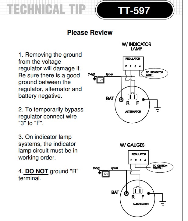
My 190xt had a new one wire alternator put on it. Since my distro tach drive is stripped I opted to go back to the alternator tach drive. Bought the old style which I guess is actually the second or new style? Whatever. Bought the 3 wire tach drive alternator from DJs. But I cannot get the alternator to charge. I'm 99% sure the wires are making solid connections on everything that is connected, and I *think* everything is wired to match the service manual. Problem is the service manual only shows for the delcotron not for an alternator? I don't hear or see any clicking from the voltage regulator. How is this thing supposed to be wired up? How can I test the voltage regulator? The service manual read like gobbldegoock. 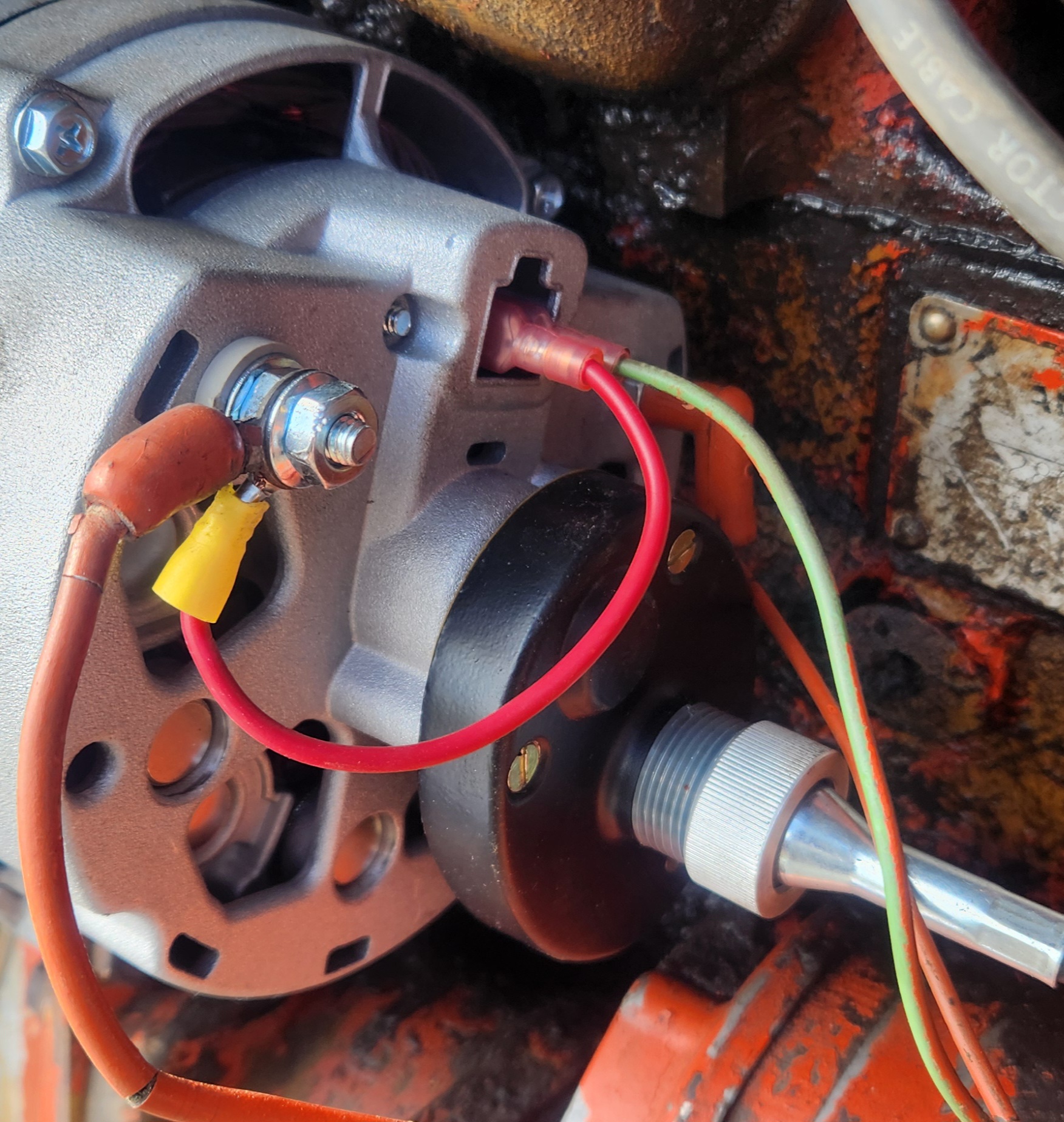 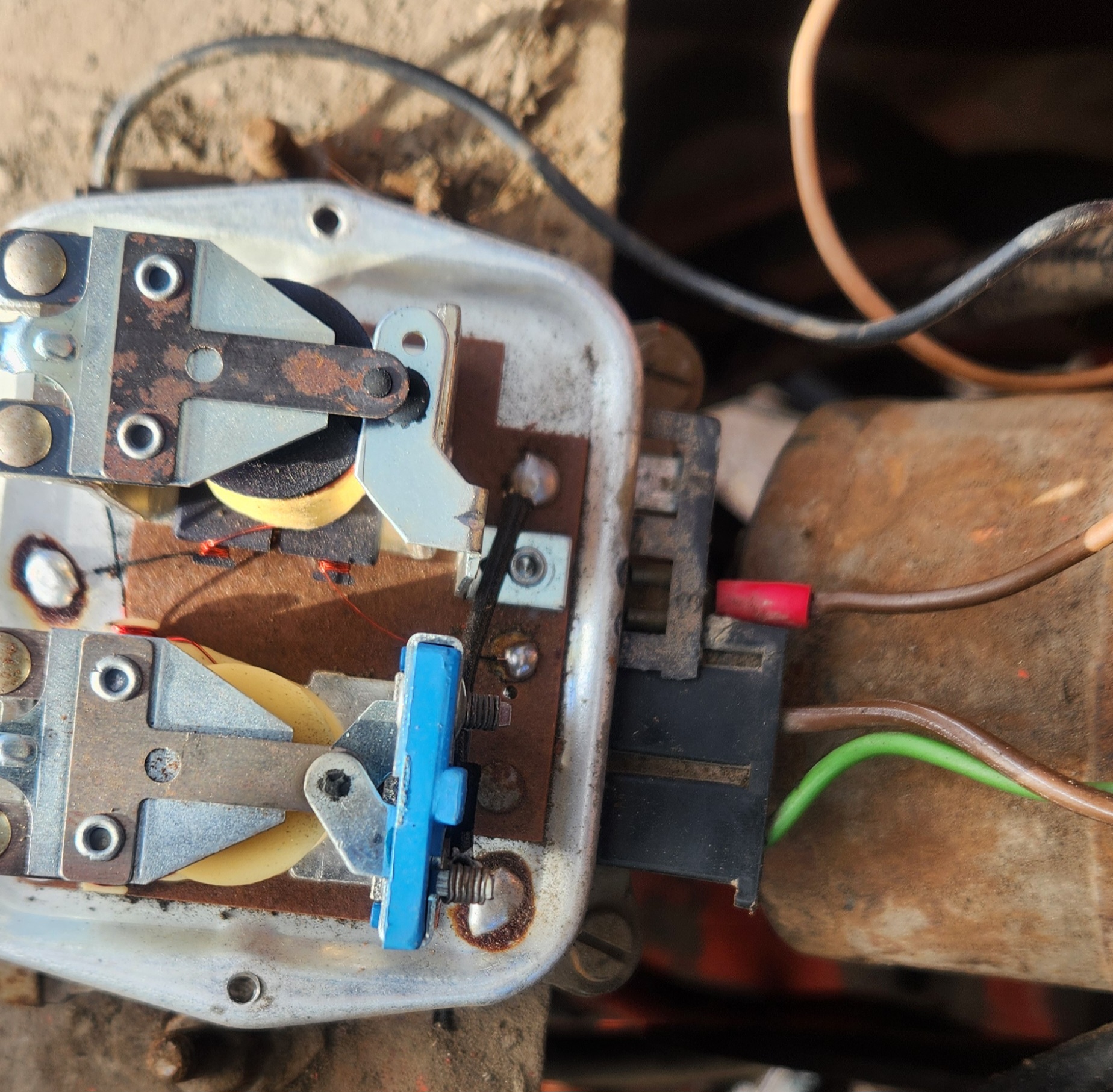
|
 |
|
Sponsored Links
|
|
|
jaybmiller
Orange Level Access

Joined: 12 Sep 2009
Location: Greensville,Ont
Points: 25271
|
Post Options
Thanks(0)
Quote Reply
Posted: 11 hours 19 minutes ago at 6:29pm |
To me that looks like an alternator with built in voltage regulator. A '3 wire' unit and not 'one wire'. For me a 'one wire' unit ONLY has the big , high current wire a 3 wire has, high current, a sense line and an ign wire.
Either of which do NOT require that external regulator
|
|
3 D-14s,A-C forklift, B-112
Kubota BX23S lil' TOOT( The Other Orange Tractor)
Never burn your bridges, unless you can walk on water
|
|
MadCow
Silver Level
Joined: 27 Aug 2023
Location: South Dakota
Points: 202
|
Post Options
Thanks(0)
Quote Reply
Posted: 10 hours 43 minutes ago at 7:05pm |
|
I think this is 3 wire. So how do I "bypass" that external reg?
I have the jumper going from power to the 'field' or regulator plug port. Should the second wire go straight to ground?
I tried all sorts of other configurations and couldn't get any charge.
|
|
KJCHRIS
Orange Level

Joined: 21 Dec 2015
Location: WC Iowa
Points: 1006
|
Post Options
Thanks(0)
Quote Reply
Posted: 10 hours 25 minutes ago at 7:23pm |
That is a Delco DN series Alternator w a mechanical tack drive. mounted to it, not sure on the regulator. FYI; There are 2 Voltage Regulators that work with the DN alternators. 1 for an Idiot light. AND 1 for an Ammeter. IF wrong Reg is used the Alt won't charge. Left wire (orange) on Alt is live at all times and goes on that left insulated terminal. FYI, I'd remove the short red wire. Where you have red wire plugged in ("F" term) should be a wire (light green) plugged in, it comes from the #1, Left hand terminal on voltage regulator. The far-left wire on Alt is a ground wire. You should hear / or feel the regulator click in when the ignition switch is turned to the RUN position. Voltage Regulator terminals; left to right, must be grounded. #1 term on V Reg is wired to "F" field Term on Alt. Live when ign sw is in run. #2 term on V Reg is wired to ign sw terminal that is on in the run position. ign sw ON. #3 term on V Reg is wired to the Battery Cable stud on Starter Solenoid. Always live. #4 term on V Reg is not used.
|
|
AC 200, CAH, AC185D bareback, AC 180D bareback, D17 III, WF. D17 Blackbar grill, NF. D15 SFW. Case 1175 CAH, Bobcat 543B,
|
|
steve(ill)
Orange Level Access

Joined: 11 Sep 2009
Location: illinois
Points: 90848
|
Post Options
Thanks(0)
Quote Reply
Posted: 10 hours 16 minutes ago at 7:32pm |
agree it looks like a DN alternator , so has an external reg.... look at the paper work and see if that is what you bought...
|
|
Like them all, but love the "B"s.
|
|
MadCow
Silver Level
Joined: 27 Aug 2023
Location: South Dakota
Points: 202
|
Post Options
Thanks(0)
Quote Reply
Posted: 10 hours 5 minutes ago at 7:43pm |
|
|
|
MadCow
Silver Level
Joined: 27 Aug 2023
Location: South Dakota
Points: 202
|
Post Options
Thanks(0)
Quote Reply
Posted: 10 hours 3 minutes ago at 7:45pm |
|
Do you know which reg for ammeter I need? I would think the reg that was on it was right?
|
|
steve(ill)
Orange Level Access
Joined: 11 Sep 2009
Location: illinois
Points: 90848
|
Post Options
Thanks(0)
Quote Reply
Posted: 10 hours 1 minutes ago at 7:47pm |
well since it says "replaces original"... i would guess they assume your using the external regulator.... couple drawings related to what Chris said....
|
|
Like them all, but love the "B"s.
|
|
MadCow
Silver Level
Joined: 27 Aug 2023
Location: South Dakota
Points: 202
|
Post Options
Thanks(0)
Quote Reply
Posted: 9 hours 46 minutes ago at 8:02pm |
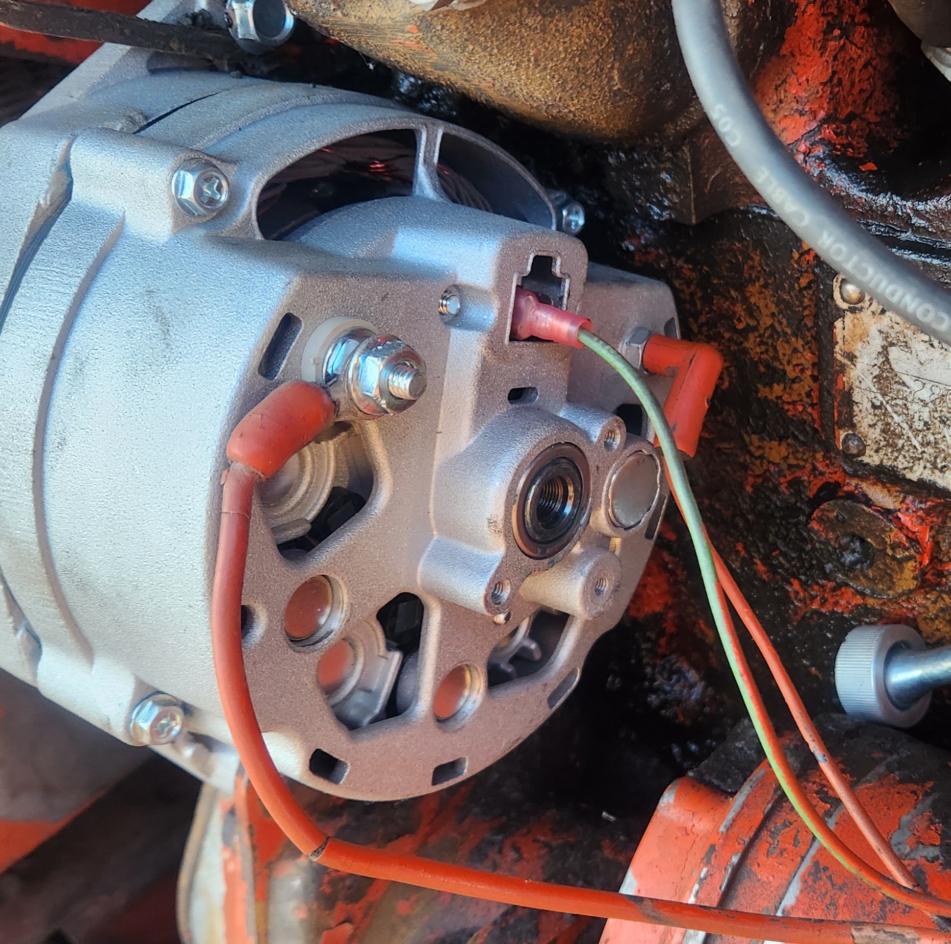 Ok. Wired like this. The big wire goes to ammeter. The "F" green wire is original wire harness and connects to the "1" post on Vreg. I've tried in both plugs, there is no marking which is 1 or F. Left it as shown in picture, left plug. The wire is good, makes noise when connecting the meter to both ends. VReg body is grounded, there is a strap connecting the body to the mounting post and I meter verified it is grounded. There is a spade terminal that isn't connected to anything that is NOT one of the front 4, it's on the side of the VReg, does that need to be grounded separate? Wire "2" on Vreg goes to the ignition switch. I have a push pull two position switch. It's connected to the open side and connects to 12+ when switch is closed and ignition on. Pole 3 at Vreg is 12+ always, connected to starter solenoid.
|
|
MadCow
Silver Level
Joined: 27 Aug 2023
Location: South Dakota
Points: 202
|
Post Options
Thanks(0)
Quote Reply
Posted: 9 hours 42 minutes ago at 8:06pm |
|
There is no clicking and the VReg doesn't do anything switch on or off, engine running or not, bad solenoid coil in the reg?
The third wire, that little post on the Alt. Whether I plug that boot in or not doesn't change anything.
When I switch lights on I drop to 11.8v, and ammeter shows draw. Lights off I'm back to 12.3v but NO charge.
|
|
MadCow
Silver Level
Joined: 27 Aug 2023
Location: South Dakota
Points: 202
|
Post Options
Thanks(0)
Quote Reply
Posted: 9 hours 41 minutes ago at 8:07pm |
|
Also I have double verified that I get very few mohm resistance in all the wires from one end to the other. So I'm confidence it's not a bad wire that I'm using.
|
|
Jim.ME
Orange Level
Joined: 19 Nov 2016
Location: Maine
Points: 974
|
Post Options
Thanks(0)
Quote Reply
Posted: 9 hours 12 minutes ago at 8:36pm |
That is a Delcotron (Delco's name for the alternators) model 10DN externally regulated alternator.
Looking at the back of the alternator, the F (field) terminal is the right spade. The R (reference aka sensing) terminal is the left terminal.
You can test the 10DN alternator by using a jumper wire between the Battery terminal and the F terminal to apply power to it. This will full field the alternator and it should give you full output power. Don't run it long that way.
Do not ground the Field wire from the regulator as it supplies power to the alternator field and grounding it can damage the regulator.
If you are trying to use the old regulator, it may be bad. 1. Test the alternator output. 2. Use a test light or voltmeter to test for power from the regulator to the alternator's F terminal. If the alternator test ok and you don't get power from the regulator, you need a new regulator. Steve at B&B can confirm, but I believe there are some electronic ones now that might be a replacement for the old ones with mechanical points.
|
|
SteveM C/IL
Orange Level Access
Joined: 12 Sep 2009
Location: Shelbyville IL
Points: 8985
|
Post Options
Thanks(0)
Quote Reply
Posted: 8 hours 51 minutes ago at 8:57pm |
|
THE EXTERNAL REG SHOULD CLICK WHEN ENERGIZED
|
|
TedN
Bronze Level

Joined: 30 Apr 2025
Location: Central WA
Points: 162
|
Post Options
Thanks(0)
Quote Reply
Posted: 7 hours 7 minutes ago at 10:41pm |
Transpo makes a regulator called a star II that effectively turns the 10dn into a one wire alternator. It mounts to one of the case bolts and has four connections; the 12v positive and negative and the field plug. I used one for many years(33 if my math is correct) on my 190XT until the insulation on the wires degraded so much I began to worry about an electrical fire. https://ebay.us/m/sAxHvLEdit - I just looked a little closer at the link I posted. It is a 24v regulator, most of them are 12v but look before you buy. I am not going to recommend one unless you are really stumped though because they always have a slight draw on the battery. I had to have a battery shutoff switch or it would die after a week or so. When I changed it out I went back to running a regulator hooked into the original harness. The electronic unit I bought is also from Transpo. https://a.co/d/03ztzofqI am not saying that Transpo products are the best, just that I have used them and have had good service life with them. I did run an extra ground to the side terminal on the regulator, but if I remember correctly it wasn't needed, but I put it in as I was wiring in an auxiliary power relay so I had the extra ground in the area anyway. Ted
Edited by TedN - 7 hours 2 minutes ago at 10:46pm
|
|
190XTD seriesIII, 190XTD seriesI, maroon belly 7000, 190XTD series??? project(or maybe parts)
|
|