| Author |
 Topic Search Topic Search  Topic Options Topic Options
|
Shade Tree 
Bronze Level

Joined: 17 Aug 2018
Location: Shiner,Texas
Points: 25
|
 Post Options Post Options
") Thanks(0) Thanks(0)
 Quote Quote  Reply Reply
 Topic: New Problem with CA. Topic: New Problem with CA.
Posted: 22 Sep 2018 at 2:50pm |
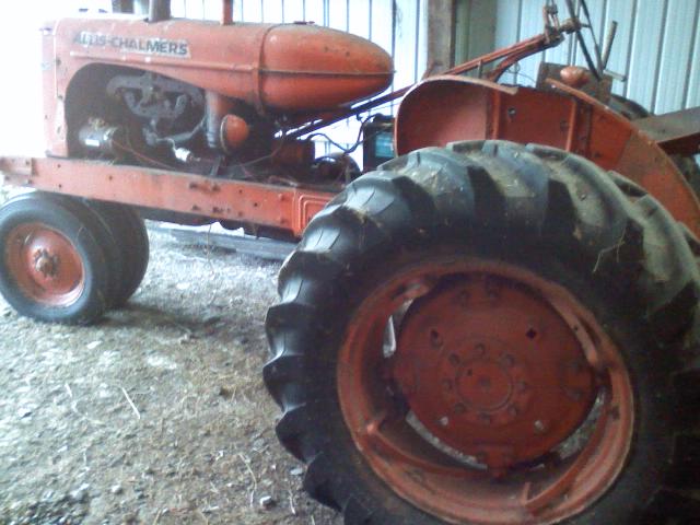
..I posted previous about locating view port for timing marks, that was solved; however, I discover when the center line is centered in the port the number two cylinder is at an apparent TDC and number 3 is very close behind it. number1 and 4 are at , or near, BDC. I have rotated over and over to make sure I am seeing what I see. I know the previous owner to be a very straight shooter, he is not one to tell it not as it is. He said the tractor was running when he parked it several years back in the shed after buying a modern tractor and the CA was never used again.
How could this be...could the fly wheel have been re-installed at some point that much off (90 degree)...and the rest be all as should be...
Welcome thoughts on how to proceed...??
Edited by Shade Tree - 22 Sep 2018 at 8:09pm
|
 |
|
Sponsored Links
|
|
|
Dakota Dave
Orange Level


Joined: 12 Sep 2009
Location: ND
Points: 3971
|
Post Options
Thanks(0)
Quote Reply
Posted: 22 Sep 2018 at 3:01pm |
|
The flywheel only fitts one way. Put you thumb over the number one spark plug hole hav a fried crank it with the hand crank till it blows you thumb out of the hole. Now stick the mag on with the rotor pointed to number one. There are two marks on the flywheel. I'm guessing your using the TDC mark it'll never run your about 30 deg off. You need to be using the fire mark. Should have a little F by the mark.
|
|
Shade Tree
Bronze Level
Joined: 17 Aug 2018
Location: Shiner,Texas
Points: 25
|
Post Options
Thanks(0)
Quote Reply
Posted: 22 Sep 2018 at 3:15pm |
..This not a magneto tractor, it has coil and distributor. The question remains, how could the timing show in the port for tdc and the number one cyl. is at or near bdc. And, not arguing, but why couldn't the flywheel be bolted on 45 degree off...is there a key-way or some thing to prevent it from bolting up..?
|
|
Sugarmaker
Orange Level
Joined: 12 Jul 2013
Location: Albion PA
Points: 8528
|
Post Options
Thanks(0)
Quote Reply
Posted: 22 Sep 2018 at 3:30pm |
My guess if like some other allis machines one of the holes in the flywheel is out of position. allowing only one installation location. Rolling it by hand and feeling the compression on the power stroke is a great way to see if number one piston is up and ready to fire. Maybe the tractor ran but not very good???:) BTW the way if it doesnt run and you cant get it to run and want to get rid of it. You can send it my way! Looks like a good CA! Regards, Chris
Edited by Sugarmaker - 22 Sep 2018 at 3:31pm
|
|
D17 1958 (NFE), WD45 1954 (NFE), WD 1952 (NFE), WD 1950 (WFE), Allis F-40 forklift, Allis CA, Allis D14, Ford Jubilee, Many IH Cub Cadets, 32 Ford Dump, 65 Comet.
|
|
TramwayGuy
Orange Level Access
Joined: 19 Jan 2010
Location: Northern NY
Points: 11755
|
Post Options
Thanks(0)
Quote Reply
Posted: 22 Sep 2018 at 3:36pm |
|
First of all, numbers 2 & 3 should both be at TDC at the exact same time. And 1 & 4 exactly 180 crankshaft degrees from 2 & 3.
Is it at all possible that the engine or flywheel came from another machine?
|
|
Hubert (Ga)engine7
Orange Level

Joined: 12 Sep 2009
Location: Jackson Cnty,GA
Points: 6471
|
Post Options
Thanks(0)
Quote Reply
Posted: 22 Sep 2018 at 3:37pm |
|
The distributor may not be installed correctly. Go with what Dakota Dave says
|
|
Just an old country boy saved by the grace of God.
|
|
Shade Tree
Bronze Level
Joined: 17 Aug 2018
Location: Shiner,Texas
Points: 25
|
Post Options
Thanks(0)
Quote Reply
Posted: 22 Sep 2018 at 4:17pm |
...I doubt that, It appears to have been been worked on some time in the past and repainted from front to the back end of torque tube...
I have looked at all the fotos of flywheels for CA and see no obvious reason why the flywheel could not be bolted a quarter round off. I would like to hear from someone who knows for sure if that could be done or not..? ...I think that could put the timing mark to show at the bottom inspection/drain under the tractor....if some one had semi-permanent mounted equipment that covered the side port that could be a work-around...?
I'm doing a lot of guessing , but would like to know more before I go on with the thing..
I appreciate everyones attention and comments..
|
|
GregLawlerMinn
Orange Level

Joined: 11 Sep 2009
Location: Lawler, Mn
Points: 1226
|
Post Options
Thanks(0)
Quote Reply
Posted: 22 Sep 2018 at 4:21pm |
|
Dakota Dave is right; before starting make sure your points are good and the gap is set at 0.020". Now onto the ignition timing, Note location of the #1 spark plug wire on the distributor cap, remove #1 spark plug, hold your finger over it (it may help if you remove all the plugs) and rotate engine until feel pressure. Insert a wire or cable tie into the hole until it contacts the piston. Slowly rotate the engine until the piston is at TDC. Remove the cap and dust cover, your rotor is pointing to where your #1 spark plug wire should be. If not correct, adjust the distributor until the rotor points to where the #1 spark plug wire is to be. Check your wire timing; firing order is 1-2-4-3 Clockwise. Loosen your distributor and fire the engine and run at idle speed. Rotate the distributor 1 direction until the engine loads up then rotate it in the opposite direction until it loads up again. Rotate it back 1/2 way between the two points. Set your engine to run at 2/3 to 3/4 throttle and repeat. If this does not work you have other issues (worn distributor, poor points/condenser/valve timing or wear)
|
|
What this country needs is more unemployed politicians-and lawyers.
Currently have: 1 D14 and a D15S2.
With new owners: 2Bs,9CAs,1WD,2 D12s,5D14s,3D15S2s, 2D17SIVs,D17D,1D19D;1 Unstyled WC
|
|
53 ca
Bronze Level
Joined: 17 Sep 2018
Location: SEMO
Points: 14
|
Post Options
Thanks(0)
Quote Reply
Posted: 22 Sep 2018 at 4:47pm |
|
There are two timing/fire marks on the flywheel 180 degrees of each other. That said flywheel will only go on one of two ways 180 degrees apart. So flywheel should be right, agreeing with others about distributor or something up there is the problem.
|
|
Jim.ME
Orange Level
Joined: 19 Nov 2016
Location: Maine
Points: 962
|
Post Options
Thanks(0)
Quote Reply
Posted: 22 Sep 2018 at 4:52pm |
Why the flywheel only fits one way, from the Allis Chalmers CA manual. 
|
|
DrAllis
Orange Level Access
Joined: 12 Sep 2009
Points: 21930
|
Post Options
Thanks(0)
Quote Reply
Posted: 22 Sep 2018 at 4:55pm |
|
There's probably two sets of timing marks on that flywheel for different chassis applications like maybe a stationary engine????
|
|
Dick L
Orange Level

Joined: 12 Sep 2009
Location: Edon Ohio
Points: 5087
|
Post Options
Thanks(0)
Quote Reply
Posted: 22 Sep 2018 at 4:55pm |
|
One bolt on the flywheel is not on the same circle as the other three. If all four bolts are in it can not be off. The most bolts you could have in if it was not correct would be two.
Finding number one piston on the way up on the compression stroke can be done with the thumb or a balloon over a fitting. Because of my crippled hand I now remove the valve cover and watch the rocker arms. Knowing that you can not have compression without the valves being closed and for the valves to be closed both of the rocker arms need to be up and loose on the valve. ( check for TDC in the inspection hole) I then set the distributor rotor pointing toward number one terminal. I then rotate the distributor back and fourth with the switch on watching for the points open with a spark. I rotate back and forth to make sure the points are just ready to spark. If TDC line is in the center of the inspection hole as it should have been you are in time. You will then find the fire line in the inspection hole when running at high idle or wide open with a timing light.
It is just that simple.
Edited by Dick L - 22 Sep 2018 at 4:57pm
|
|
Dick L
Orange Level
Joined: 12 Sep 2009
Location: Edon Ohio
Points: 5087
|
Post Options
Thanks(1)
Quote Reply
Posted: 22 Sep 2018 at 5:01pm |
 DrAllis wrote: DrAllis wrote:
There's probably two sets of timing marks on that flywheel for different chassis applications like maybe a stationary engine???? |
I have a stack of flywheels for those engines out in the shed and none have two sets of timing marks. I have found one or two without any marks.
|
|
Dick L
Orange Level
Joined: 12 Sep 2009
Location: Edon Ohio
Points: 5087
|
Post Options
Thanks(0)
Quote Reply
Posted: 22 Sep 2018 at 5:20pm |
[ I discover when the center line is centered in the port the number two cylinder is at an apparent TDC and number 3 is very close behind it. number1 and 4 are at , or near, BDC. I have rotated over and over to make sure I am seeing what I see. The only way number three could be close behind it would have been someone cut off an eight cylinder crankshaft and stuck it in. 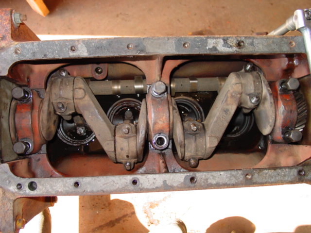 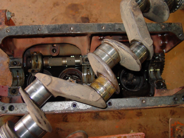 At the link is more pictures of the inside of your engine. You can click at the top and see a bunch more. https://public.fotki.com/DickL/allis_chalmers_engi/allis-chalmers-c-st/
Edited by Dick L - 22 Sep 2018 at 5:20pm
|
|
DaveKamp
Orange Level Access
Joined: 12 Apr 2010
Location: LeClaire, Ia
Points: 6077
|
Post Options
Thanks(1)
Quote Reply
Posted: 22 Sep 2018 at 7:46pm |
|
If 2 and 3 are not in identical positions, then the logical conclusion is either a bent or broken crank, or a bent connecting rod.
Running when parked implies just that... and whatever happened after is entirely unknown. I've pulled apart engines that were driven to where parked, and over time, wound up with broken cranks and bent rods due to things like... accumulating water, and getting frozen (expansion)... or someone pulling or pushing it out of the weeds when one cylinder's rings were stuck.
I would turn it by hand with probes in the plug holes, or pull the head, and check piston position with exactitude.
|
|
Ten Amendments, Ten Commandments, and one Golden Rule solve most every problem. Citrus hand-cleaner with Pumice does the rest.
|
|
Shade Tree
Bronze Level
Joined: 17 Aug 2018
Location: Shiner,Texas
Points: 25
|
Post Options
Thanks(0)
Quote Reply
Posted: 22 Sep 2018 at 7:56pm |
Dick L wrote:
One bolt on the flywheel is not on the same circle as the other three. If all four bolts are in it can not be off. The most bolts you could have in if it was not correct would be two.
Finding number one piston on the way up on the compression stroke can be done with the thumb or a balloon over a fitting. Because of my crippled hand I now remove the valve cover and watch the rocker arms. Knowing that you can not have compression without the valves being closed and for the valves to be closed both of the rocker arms need to be up and loose on the valve. ( check for TDC in the inspection hole) I then set the distributor rotor pointing toward number one terminal. I then rotate the distributor back and fourth with the switch on watching for the points open with a spark. I rotate back and forth to make sure the points are just ready to spark. If TDC line is in the center of the inspection hole as it should have been you are in time. You will then find the fire line in the inspection hole when running at high idle or wide open with a timing light.
It is just that simple. |
...except, when the #1 piston is at TDC on firing stroke and the flywheel center line mark is 90 degrees past the left side inspection port, not visible. I visually watched the #1 come to TDC through the spark plug hole and verified it with the rocker arms being unloaded. The rest is pretty elementary as far as setting distributor timing and point gap...I'm 78 years old and have been a mechanic for most of those years. I am just mystified with the position of the flywheel being being contrary to what the manuals say. I don't have a manual for these tractors so I am going to download one tonight so I can see what might be going on.
Once again, thanks for all the suggestions. Stan in South Texas.
|
|
Dick L
Orange Level
Joined: 12 Sep 2009
Location: Edon Ohio
Points: 5087
|
Post Options
Thanks(0)
Quote Reply
Posted: 22 Sep 2018 at 10:05pm |
90º puts the mark on the bottom then most likely? If that is so then when the rocker arms are loose on the compression stroke forget the marks and set the distributor ready for the to be ready to open and forget the marks. That will be TDC regardless where the marks are. I never tried to put a WC flywheel on the B's or C's that I have but I understand the ring gears will interchange even though they have a different tooth count. A guy in the area I helped a few years back had to have a WC Bendix on his B to match his ring gear. One of my starters for a B would not work is how we found it. He bought the tractor that way. Being 80 I have worked on a few engines myself and since being on the internet I have never had to ask anyone how to make one work. I am happy to help anyone that wants help. If both rocker arms on number one piston are loose and the number one piston is not at top dead center you get to remove the timing cover and line up the timing marks. If it does have the correct flywheel that would be the only way the timing marks would not be in the inspection hole. 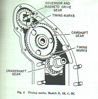 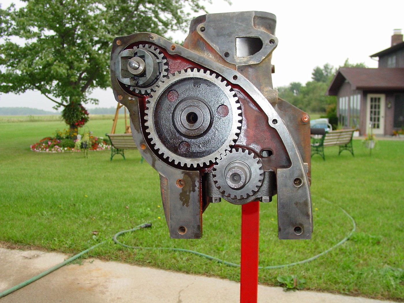
Edited by Dick L - 22 Sep 2018 at 11:46pm
|
|
Dick L
Orange Level
Joined: 12 Sep 2009
Location: Edon Ohio
Points: 5087
|
Post Options
Thanks(0)
Quote Reply
Posted: 23 Sep 2018 at 7:52am |
Weighing all your observations against how the engine is built I don't think you have actually had number one piston at TDC. You said you observed number two with number three close behind it. On four cylinder engines two pistons are at the same place in the cylinders at the same time. When number two and three are at TDC One and four are at the exact bottom. With number one being at TDC on the compression stroke number four is also at TDC only on the exhaust stroke rather than the compression stroke. Firing to the plugs on the cylinder at the proper time is achieved with the crankshaft rotating two times for each time the camshaft rotates one time. If you do have the number one piston at the very top and can feel it with a wire change directions moving the crankshaft back and forth with the rocker arms loose at the change of piston direction you are at TDC on the compression stroke and a different flywheel. If the above can not be proven the way I laid it out they your camshaft is out of time. If it is in time it will start and run with fuel. The flywheel is no big deal as you can remark it if desire to see marks with a timing light. Knowing the piston is at the exact top the TDC or CENTER line can be marked through the hole. You can glue a cheap plastic protractor to the end of the crankshaft at TDC and turn the engine backward 30º and mark the FIRE line. Timing lights were used very little on these engine in the 30's and 40's to set timing. 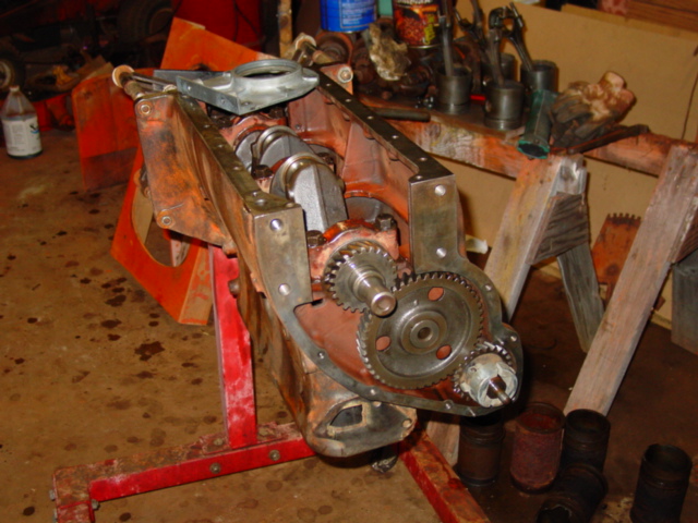
Edited by Dick L - 23 Sep 2018 at 8:11am
|
|
Shade Tree
Bronze Level
Joined: 17 Aug 2018
Location: Shiner,Texas
Points: 25
|
Post Options
Thanks(0)
Quote Reply
Posted: 23 Sep 2018 at 9:29am |
Dick L wrote:
Weighing all your observations against how the engine is built I don't think you have actually had number one piston at TDC. You said you observed number two with number three close behind it. On four cylinder engines two pistons are at the same place in the cylinders at the same time. When number two and three are at TDC One and four are at the exact bottom. With number one being at TDC on the compression stroke number four is also at TDC only on the exhaust stroke rather than the compression stroke. Firing to the plugs on the cylinder at the proper time is achieved with the crankshaft rotating two times for each time the camshaft rotates one time.
If you do have the number one piston at the very top and can feel it with a wire change directions moving the crankshaft back and forth with the rocker arms loose at the change of piston direction you are at TDC on the compression stroke and a different flywheel. If the above can not be proven the way I laid it out they your camshaft is out of time. If it is in time it will start and run with fuel.
The flywheel is no big deal as you can remark it if desire to see marks with a timing light. Knowing the piston is at the exact top the TDC or CENTER line can be marked through the hole. You can glue a cheap plastic protractor to the end of the crankshaft at TDC and turn the engine backward 30º and mark the FIRE line. Timing lights were used very little on these engine in the 30's and 40's to set timing.
...I appreciate all the input. I should have said it different; As it was, the #1 and #4 were at apparent BDC and the #2 and #3 were at apparent TDC determined by using a piece of wire. At that time I had not removed the valve cover. Subsequently, I determined the TDC of #1 by observation with a light, seeing the piston rise to the carbon/wear mark inside the liner and checking that the rockers were unloaded. Again, at this point I had accepted the flywheel indicators being 90 degrees off (still don't know or understand why) and decided to time the distributor to the #1 at TDC and go from there. I am doing this outside with out cover or shade and in between showers...having to throw a tarp over it all and go inside when it rains....  .
I am going to have to run into town now and get a new set of points, rotor, cap and wires...I have replaced the coil as the old one had a crack in the neck and replaced the condenser....should have done it all but, I'm a miser....Last night I spun the engine and was getting fire but not enough to get it running. I replaced the carb gasket early on before I got this far into it..and did a quick, not thorough, carb clean (it didn't look too bad, no crude and dry).. I'm going to do that again, clearing all the passages with gauge wire and carb cleaner with air pressure nozzle. I also have a new float valve and seat to install...however the old seems to be working fine....doesn't leak.
One more thing, I noticed after all the spinning I've done, that the rocker arms were not getting oil. I opened the supply lines to the filter (spin-on) and all clear, but no oil. Shouldn't free spin with the starter (no plugs in) be enough to supply oil to top of engine. Also, when I removed filter there was no oil to run out.... . Is there anything I can do short of splitting the tractor to revive or prime the oil pump. Is there a strainer or screen that could be cleaned before more drastic measures are taken..?
|
|
|
Dick L
Orange Level
Joined: 12 Sep 2009
Location: Edon Ohio
Points: 5087
|
Post Options
Thanks(0)
Quote Reply
Posted: 23 Sep 2018 at 9:43am |
Rocker arm rapid movement brings the oil over the top of the rocker arms. It works but is different than most auto's. If you take it apart you would think it could not work as it does. 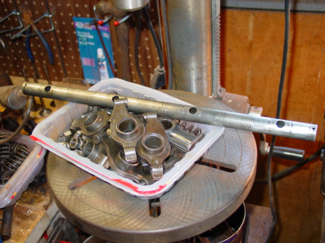 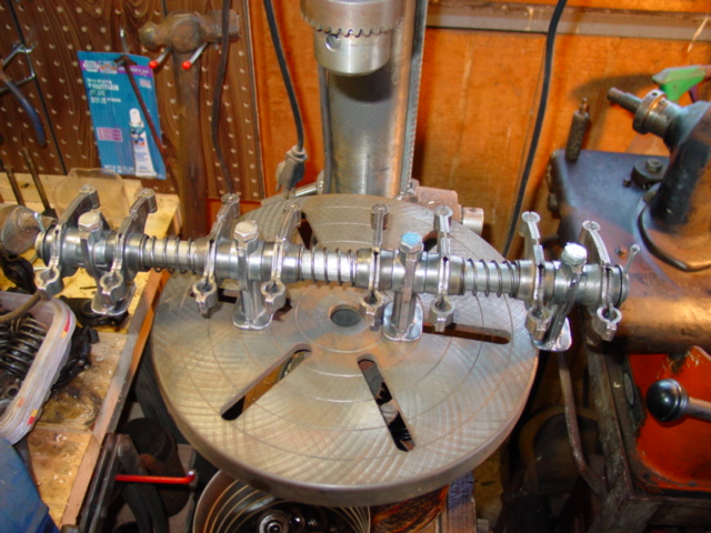
|
|
Shade Tree
Bronze Level
Joined: 17 Aug 2018
Location: Shiner,Texas
Points: 25
|
Post Options
Thanks(0)
Quote Reply
Posted: 23 Sep 2018 at 9:53am |
...Dick L.
I don't seem to be getting oil to oil gallery...nothing at the supply line to the filter and pressure gauge. Is there a screen that could cleaned without tearing into the engine...or some way to prime the pump...or otherwise check it out ...really not wanting to do a tear down...?
|
|
Dick L
Orange Level
Joined: 12 Sep 2009
Location: Edon Ohio
Points: 5087
|
Post Options
Thanks(1)
Quote Reply
Posted: 23 Sep 2018 at 11:58am |
|
The oil pump will need primed. Several ways to prime it getting oil into the vane pump so it is not just pumping air. These pumps are not self priming. What I think is the easiest way is to remove the filter, place a gas line hose on the stand pump. I like a hose long enough to hang over the rocker arms but a short hose and a can will work just as well. I fill the hose with motor oil and let it seep down for a couple minutes and refill and start the engine. If the engine is not running it can be done with the starter spinning until oil comes out the hose. When oil is flowing out the hose I stop the engine, remove the hose, replace the filter and restart the engine and watch the gage come up. If it does not come up I would refill one more time the same way. If it still does not come up the pan comes off to check the suction tube. I have never had it not build pressure to first time if I get a good flow of oil out the hose.
|
|
Dick L
Orange Level
Joined: 12 Sep 2009
Location: Edon Ohio
Points: 5087
|
Post Options
Thanks(1)
Quote Reply
Posted: 23 Sep 2018 at 12:11pm |
Shade Tree wrote:
...Dick L.
I don't seem to be getting oil to oil gallery...nothing at the supply line to the filter and pressure gauge. Is there a screen that could cleaned without tearing into the engine...or some way to prime the pump...or otherwise check it out ...really not wanting to do a tear down...?
|
I only read the first sentence when my wife needed help and I didn't go back and read it again with the rest of what you typed.
|
|
Shade Tree
Bronze Level
Joined: 17 Aug 2018
Location: Shiner,Texas
Points: 25
|
Post Options
Thanks(0)
Quote Reply
Posted: 03 Oct 2018 at 8:53am |
|
....after checking and re-checking the distributor timing, fuel supply, wiring for fire,...don't know how many times, and trying to start with no luck, I tried one more time last night and it started and ran perfect on the first crank..I am relieved, to say the least ...but still mystified at why prior attempts failed...Oh well...!
|
|
Shade Tree
Bronze Level
Joined: 17 Aug 2018
Location: Shiner,Texas
Points: 25
|
Post Options
Thanks(0)
Quote Reply
Posted: 03 Oct 2018 at 8:54am |
Dick L wrote:
Shade Tree wrote:
...Dick L.
I don't seem to be getting oil to oil gallery...nothing at the supply line to the filter and pressure gauge. Is there a screen that could cleaned without tearing into the engine...or some way to prime the pump...or otherwise check it out ...really not wanting to do a tear down...?
|
I only read the first sentence when my wife needed help and I didn't go back and read it again with the rest of what you typed. |
I did as suggested...primed the pump and there it was...plenty of oil flowing now...Thanks.
|
|


