| Author |
 Topic Search Topic Search  Topic Options Topic Options
|
grinder220 
Orange Level

Joined: 11 Jan 2012
Location: Clinton Iowa
Points: 2381
|
 Post Options Post Options
") Thanks(0) Thanks(0)
 Quote Quote  Reply Reply
 Topic: Off color MM UB diesel electrical? Topic: Off color MM UB diesel electrical?
Posted: 11 hours 58 minutes ago at 8:50am |
|
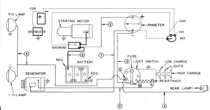
I need some help figuring out the correct way to wire the light switch up. When I bought the tractor the original switch was missing one wire,seized up and broken at one terminal. Its a 3 position push/pull switch with built in resistor very similar to what a WD-WD45 uses to control the charging system. Actually the aftermarket POS Chinese switch is the same between the 2. Anyways the wire frome the resistor was missing on the original switch, one terminal went to the fuse/lights the other to the voltage regulator. Should the wire from the resistor go to the load side of the amp gauge? There is no wiring diagram in the operators, parts or repair manual for this tractor and I can't find anything online. There's online diagrams for the gas tractors but they use a completely different style of switch as that switch also controls the ignition system.
|
 |
|
Sponsored Links
|
|
|
steve(ill)
Orange Level Access
Joined: 11 Sep 2009
Location: illinois
Points: 90994
|
Post Options
Thanks(0)
Quote Reply
Posted: 11 hours 9 minutes ago at 9:39am |
first of all i know NOTHING about your MM.... second, the RESISTOR on the light switch was VERY COMMON 70 years ago on 6 volt systems WITHOUT a voltage regulator... LIght ON - max charge.. Lights OFF - minimal charge... Very simple..
Years later they changed to voltage regulators on 12 volt systems... and many 6 volt systems were upgraded with a regulator and ELIMINATE the resistor...
---------- if you are 12v.... or 6v with a voltage regulator.. you dont need the resistor... just a simple ON- OFF switch for the headlights.
Edited by steve(ill) - 11 hours 7 minutes ago at 9:41am
|
|
Like them all, but love the "B"s.
|
|
steve(ill)
Orange Level Access
Joined: 11 Sep 2009
Location: illinois
Points: 90994
|
Post Options
Thanks(0)
Quote Reply
Posted: 11 hours 5 minutes ago at 9:43am |
|
the resistor was feed by the "F" wire from the 6V generator and the other side of the resistor was grounded thru the switch for LO CHARGE.... to get HI CHARGE, the switch bypassed the resistor and Grounded the "F" wire..
|
|
Like them all, but love the "B"s.
|
|
Les Kerf
Orange Level
Joined: 08 May 2020
Location: Idaho
Points: 1658
|
Post Options
Thanks(0)
Quote Reply
Posted: 11 hours 1 minutes ago at 9:47am |
 grinder220 wrote: grinder220 wrote:
... Its a 3 position push/pull switch with built in resistor very similar to what a WD-WD45 uses to control the charging system... |
I have never so much as touched any M-M. The Allis system uses the resistor to apply either a Full-ground to the generator field (High Charge), or a Partial-ground through the resistor (Low Charge). The resistor is not connected to the ammeter or any other power source.
|
|
Les Kerf
Orange Level
Joined: 08 May 2020
Location: Idaho
Points: 1658
|
Post Options
Thanks(0)
Quote Reply
Posted: 10 hours 54 minutes ago at 9:54am |
Wiring diagram for a typical AC Model CA
|
|
TedN
Bronze Level

Joined: 30 Apr 2025
Location: Central WA
Points: 180
|
Post Options
Thanks(0)
Quote Reply
Posted: 10 hours 42 minutes ago at 10:06am |
|
We have a mostly original ZB in my mom's shop. It is similar vintage so the wiring should be the same, I will try to remember to look at it today.
Edit - I just reread the original post, our ZB is gas. I will look anyway.
Ted
Edited by TedN - 10 hours 39 minutes ago at 10:09am
|
|
190XTD seriesIII, 190XTD seriesI, maroon belly 7000, 7045, 190XTD series??? project(or maybe parts)
|
|
grinder220
Orange Level
Joined: 11 Jan 2012
Location: Clinton Iowa
Points: 2381
|
Post Options
Thanks(0)
Quote Reply
Posted: 9 hours 44 minutes ago at 11:04am |
It is a factory 12v system. Here is a picture of the new switch and the original for comparison. The charging system was not functioning when i bought it. The regulator was shot,not sure on generator condition yet. So the lights should be connected to the resistor terminal then? What wire goes to the fuse on the switch then? Original has a fuse on the dash like a hundred series allis uses. Does the regulator break connection on its own then the generator stops spinning? 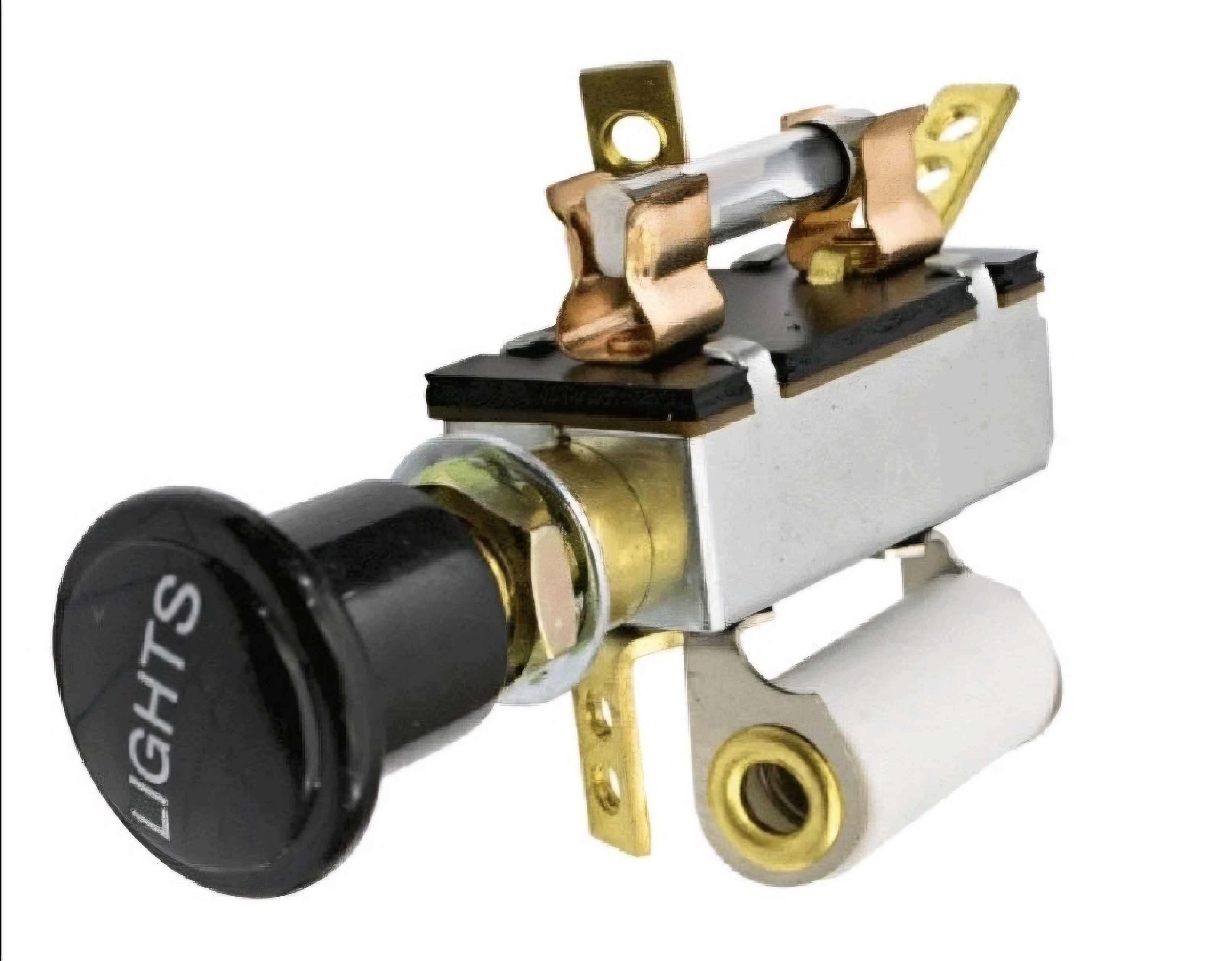 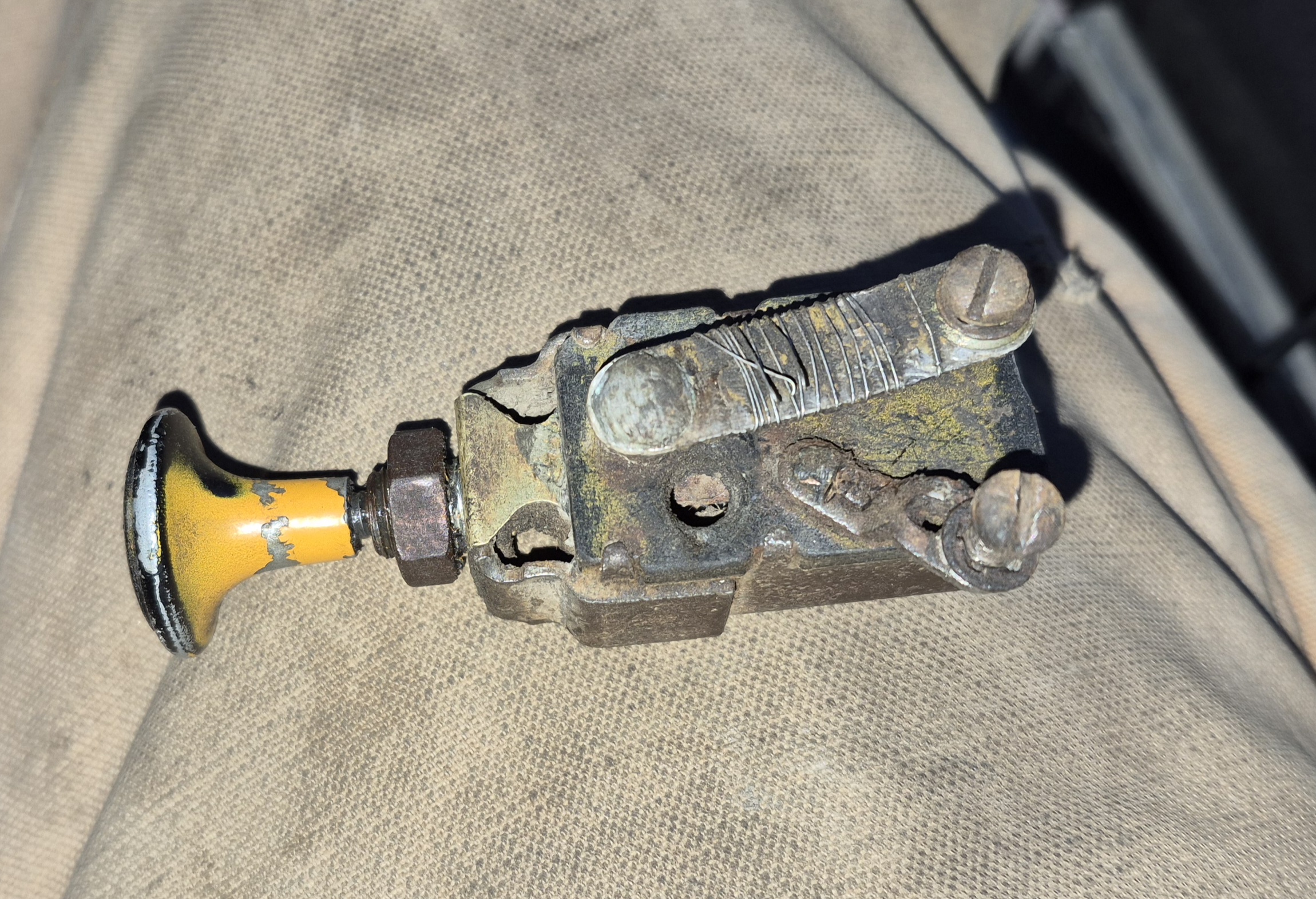
|
|
Les Kerf
Orange Level
Joined: 08 May 2020
Location: Idaho
Points: 1658
|
Post Options
Thanks(0)
Quote Reply
Posted: 7 hours 47 minutes ago at 1:01pm |
grinder220 wrote:
It is a factory 12v system... The regulator was shot,not sure on generator condition yet... |
Ok, I don't believe that anything Steve and I stated above is applicable to your system. We were both referring to the 6 Volt Allis system that uses a simple cutout relay and has no discrete Voltage Regulator as such.
grinder220 wrote:
So the lights should be connected to the resistor terminal then? |
I truly don't know for certain but I doubt it. If I had it in my hand I would use an ohmmeter to try to determine how the resistor is connected in the switch.
grinder220 wrote:
What wire goes to the fuse on the switch then? Original has a fuse on the dash like a hundred series allis uses. |
I would expect one end of the fuse to connect to the ammeter and the other end serve the lights
grinder220 wrote:
Does the regulator break connection on its own then the generator stops spinning? |
Most "A" circuit regulators apply ground at the regulator, they typically use a built-in resistor and automatically switch back-and-forth between full ground and resistive ground. I have no idea why your system has a separate resistor if it has an actual Voltage regulator
|
|
steve(ill)
Orange Level Access
Joined: 11 Sep 2009
Location: illinois
Points: 90994
|
Post Options
Thanks(0)
Quote Reply
Posted: 7 hours 30 minutes ago at 1:18pm |
it still makes no sense to have the resistor if you have a Voltage Regulator.... Are you looking at a CUTOUT BOX, or a real REGULATOR ? How many terminals does it have going to it ?
If the ORIGINAL switch had a resistor... then its possible they did a DELETE and installed a voltage regulator instead... Dont need BOTH..
|
|
Like them all, but love the "B"s.
|
|
steve(ill)
Orange Level Access
Joined: 11 Sep 2009
Location: illinois
Points: 90994
|
Post Options
Thanks(0)
Quote Reply
Posted: 7 hours 27 minutes ago at 1:21pm |
unless the resistor is a head light DIMMER.... but i see no need for that..
GOOGLE-----On older Minneapolis Moline tractors with 3-position (Off-Dim-Bright) light switches, the resistor serves two primary functions depending on the switch position: it either dims the lights (usually in the 'D' position) or acts as a generator field resistor to control charge rates in cut-out relay systems.
- Light Dimming: In the DIM position, the current passes through the resistor to reduce voltage, lowering the brightness of the headlights.
- Generator Charge Control: It assists in regulating the generator field, allowing the system to switch between high and low charging rates based on whether the lights are on.
- Application: These resistors are generally found on tractors using a cutout relay rather than a modern voltage regulator.
Edited by steve(ill) - 7 hours 25 minutes ago at 1:23pm
|
|
Like them all, but love the "B"s.
|
|
grinder220
Orange Level
Joined: 11 Jan 2012
Location: Clinton Iowa
Points: 2381
|
Post Options
Thanks(0)
Quote Reply
Posted: 7 hours 12 minutes ago at 1:36pm |
It's a regulator not a cut-out,the broken wire shown is for the front right headlight 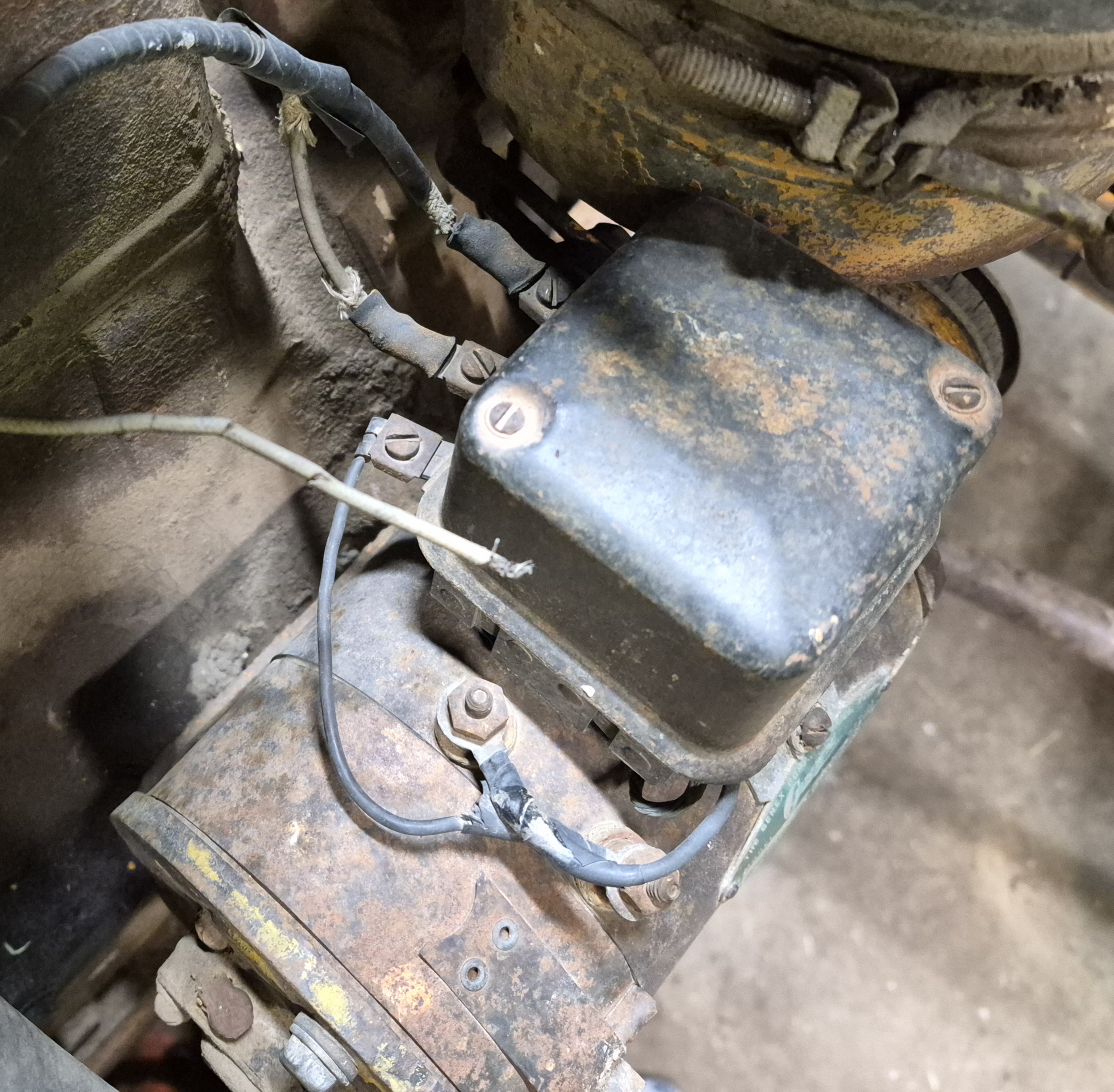
|
|
grinder220
Orange Level
Joined: 11 Jan 2012
Location: Clinton Iowa
Points: 2381
|
Post Options
Thanks(0)
Quote Reply
Posted: 7 hours 5 minutes ago at 1:43pm |
Here's a picture from the parts book, doesn't state regulator or cutout 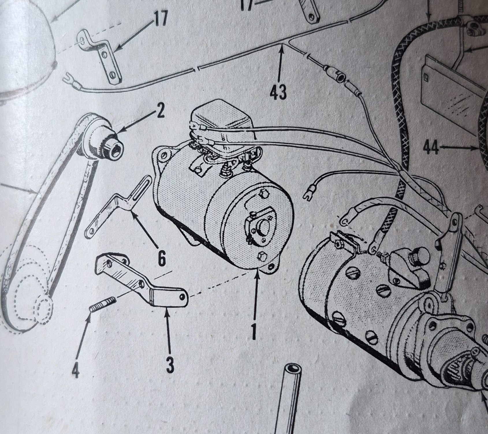
|
|
Les Kerf
Orange Level
Joined: 08 May 2020
Location: Idaho
Points: 1658
|
Post Options
Thanks(0)
Quote Reply
Posted: 5 hours 6 minutes ago at 3:42pm |
grinder220 wrote:
Here's a picture from the parts book, doesn't state regulator or cutout... |
It has multiple wires going to it so it is must be a regulator rather than a cutout.
With an actual regulator you definitely do NOT want that resistor connected to anything involving the charging system.
As far as dimming your lights, I would leave that alone until you can get it charging properly.
|
|
steve(ill)
Orange Level Access
Joined: 11 Sep 2009
Location: illinois
Points: 90994
|
Post Options
Thanks(0)
Quote Reply
Posted: 4 hours 43 minutes ago at 4:05pm |
Agree... with a voltage regulator, the ONLY THING a resistor on the light switch could be used for would be to Dim the Lights..
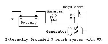
if your regulator has 3 terminals ( none on the bottom) then it wires like this.. If the regulator is 20 years old or more, it probably is causing problems with charge..
If you have a 4 terminal regulator ( one on the bottom)... then the "L" terminal on the side can be used to feed the LIGHTS..
Edited by steve(ill) - 4 hours 34 minutes ago at 4:14pm
|
|
Like them all, but love the "B"s.
|
|
grinder220
Orange Level
Joined: 11 Jan 2012
Location: Clinton Iowa
Points: 2381
|
Post Options
Thanks(0)
Quote Reply
Posted: 4 hours 37 minutes ago at 4:11pm |
|
Ok, I want to make sure I hook up the switch correctly. The terminal with the fuse would go to the amp gauge,the resistor to the lights and the other to the regulator then, is that correct?
|
|
steve(ill)
Orange Level Access
Joined: 11 Sep 2009
Location: illinois
Points: 90994
|
Post Options
Thanks(0)
Quote Reply
Posted: 4 hours 31 minutes ago at 4:17pm |
i would guess that the OUTLET from the amp meter is the HOT feeding the resistor.... and other OUTLET of the resistor goes to the lights... somehow when you pull the switch to BRIGHT, it bypasses the resistor and puts the amp / power straight to the lights.
You want to make sure that the NEW SWITCH does not GROUND the RESISTOR outlet side to the SWITCH CASE.... thats what MOST of them do when used with the 6V generator.
Edited by steve(ill) - 4 hours 30 minutes ago at 4:18pm
|
|
Like them all, but love the "B"s.
|
|
Les Kerf
Orange Level
Joined: 08 May 2020
Location: Idaho
Points: 1658
|
Post Options
Thanks(0)
Quote Reply
Posted: 3 hours 53 minutes ago at 4:55pm |
steve(ill) wrote:
You want to make sure that the NEW SWITCH does not GROUND the RESISTOR outlet side to the SWITCH CASE.... thats what MOST of them do when used with the 6V generator. |
Yup. If that new switch is indeed identical to an Allis-Chalmers style light switch then the resistor will apply ground and you will let the smoke out of something that you would rather retain un-smoked.
I would NOT connect that resistor to ANYTHING for now.
|
|
steve(ill)
Orange Level Access
Joined: 11 Sep 2009
Location: illinois
Points: 90994
|
Post Options
Thanks(0)
Quote Reply
Posted: 2 hours 44 minutes ago at 6:04pm |
|
Agree... the resistor is Useless.. Forget it... You can use the switch to turn the lights ON and OFF... thats all you need on that end.. For the CHARGE system, follow the drawing above for the regulator / generator..
|
|
Like them all, but love the "B"s.
|
|