| Author |
 Topic Search Topic Search  Topic Options Topic Options
|
Oldoug 
Orange Level Access

Joined: 12 Sep 2009
Points: 1139
|
 Post Options Post Options
") Thanks(0) Thanks(0)
 Quote Quote  Reply Reply
 Topic: Gleaner A II variable speed drive Topic: Gleaner A II variable speed drive
Posted: 08 Jan 2024 at 3:22pm |
I've been working on a 1966 A II Gleaner. I've been having problems with the variable speed drive...I can get the variable speed to get the ground speed to go faster but will not slow down. Off the hydraulic valve stack there is a single hose that feeds the variable speed, so the oil is supplied and returned through the same line. When I operate the valve spool stroke full in and out manually it supplies oil over the the variable speed but will not return the oil back, I have remove the oil supply line to relieve the pressure on the varilabe speed get it to return back to the slow position. I guess my question is what is suppose to happen in the valve stack to allow the oil to return to the sump? There is a poppet valve in the valve stack, but from what I can tell that is there to hold the pressure in the fast speed posistion...something has to tell the poppet valve to release the pressue when you want to slow down? Just wondering if anybody else has run across this problem before or not...Thank you.
|
|
Matt Folkers
FOLKERS RESTORATION
Restoring vintage things to last so the future can enjoy our past.
|
 |
|
Sponsored Links
|
|
|
8070nc
Orange Level Access
Joined: 21 Mar 2019
Location: North Carolina
Points: 649
|
Post Options
Thanks(0)
Quote Reply
Posted: 08 Jan 2024 at 4:34pm |
|
I would try to remove the linkage from the spool and push it towards slow by hand to see if slows down. If it does the linkage needs attention.
|
|
1984 80780
1957 D14
DES 300 with 25000 engine
616 tractor
|
|
Oldoug
Orange Level Access
Joined: 12 Sep 2009
Points: 1139
|
Post Options
Thanks(0)
Quote Reply
Posted: 08 Jan 2024 at 7:25pm |
|
I have the linkage disconnected and am operating the valve spool manually by hand full stroke in and out.
|
|
Matt Folkers
FOLKERS RESTORATION
Restoring vintage things to last so the future can enjoy our past.
|
|
8070nc
Orange Level Access
Joined: 21 Mar 2019
Location: North Carolina
Points: 649
|
Post Options
Thanks(0)
Quote Reply
Posted: 08 Jan 2024 at 8:56pm |
|
Could it be in the hose? Different situation but same principle. I had a dragging brake caliper one time. Changed the caliper, same thing. It would brake fine just wouldnt release. Changed the brake hose and it fixed it. A piece of the inner liner seperated and was folding back holding pressure on the caliper
|
|
1984 80780
1957 D14
DES 300 with 25000 engine
616 tractor
|
|
im4racin
Orange Level
Joined: 12 Jun 2017
Location: Garrison ND
Points: 1079
|
Post Options
Thanks(0)
Quote Reply
Posted: 08 Jan 2024 at 10:10pm |
|
When you crack the line to bleed off pressure and return to slow…where are you opening the line? Near the cyl or at the valve stack?
|
|
Oldoug
Orange Level Access
Joined: 12 Sep 2009
Points: 1139
|
Post Options
Thanks(0)
Quote Reply
Posted: 08 Jan 2024 at 10:43pm |
|
Hose is new…oil goes to the variable speed and drains out when I unhook it at the valve stack to relieve the pressure.
|
|
Matt Folkers
FOLKERS RESTORATION
Restoring vintage things to last so the future can enjoy our past.
|
|
Oldoug
Orange Level Access
Joined: 12 Sep 2009
Points: 1139
|
Post Options
Thanks(0)
Quote Reply
Posted: 08 Jan 2024 at 10:44pm |
|
At the valve stack…it’s easier to access there.
|
|
Matt Folkers
FOLKERS RESTORATION
Restoring vintage things to last so the future can enjoy our past.
|
|
8070nc
Orange Level Access
Joined: 21 Mar 2019
Location: North Carolina
Points: 649
|
Post Options
Thanks(0)
Quote Reply
Posted: 09 Jan 2024 at 1:35am |
|
You are ahead of me on every step. On an open center system it hard to imagine it internal to the valve. Only thing I can think of now is that splool has to have some sort of spring centering mechinism. I have seen dirt and rust accumulate in the centering part preventing full stroke of the spool. Wish I could help you more but thats all I can think of from a distance
Good luck. Oh that doesnt mean Ill stop thinking about it I just dont know what else right now
|
|
1984 80780
1957 D14
DES 300 with 25000 engine
616 tractor
|
|
DrAllis
Orange Level Access
Joined: 12 Sep 2009
Points: 22177
|
Post Options
Thanks(0)
Quote Reply
Posted: 09 Jan 2024 at 6:46am |
|
Remove the hose from the valve. Reach down in the hole and see if there isn't a hollow allen head nut. Remove it and there may be a "floating" brass orifice under the hollow allen nut. Remove the orifice and clean out the plugged hole. Make sure you KNOW which way the orifice goes in up/down.
|
|
AC7060IL
Orange Level
Joined: 19 Aug 2012
Location: central IL
Points: 3582
|
Post Options
Thanks(0)
Quote Reply
Posted: 09 Jan 2024 at 7:11am |
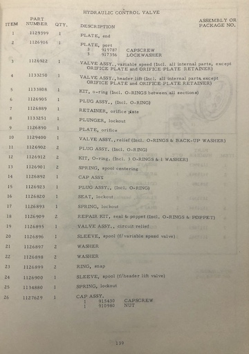
Remove the valve's spool rod(plunger)from it's body. There is usually a snap ring at it's front. The rear can be a hollow nut?. Once the spool is removed, clean/inspect all the dirty oil from within it. If you find more than just dirty oil(yucky solids?), then unbolt the valve body from it's valve stack(multiple valves sandwiched together?), if that is how its arranged? And, thoroughly clean all valves/springs/portals, etc. Probably best to replace o-rings at this time?
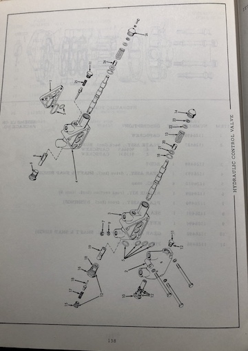
Here's a copy of Gleaner AII Dealers Parts Catalog, Section II - Combine, March 1965, hydraulic control valve pages 138 & 139. I believe the valve you're interesting in is Valve #3.
Edited by AC7060IL - 09 Jan 2024 at 9:15am
|
|
Oldoug
Orange Level Access
Joined: 12 Sep 2009
Points: 1139
|
Post Options
Thanks(0)
Quote Reply
Posted: 09 Jan 2024 at 10:59am |
|
Valve three is my stack in question…I’ve had this all apart…when you call to speed up the variable speed oil flows through port past the poppet number 18…once you are done calling for oil spring 17 pushes the poppet closed….when you want to slow down something has to release the poppet…I’m guessing the relief valve number 19 has to move forward and push the metal stem of poppet to release the oil back into the valve…is that a correct line of thinking? I’ve had this section apart on the bench and by shining light and adding oil and operating the spool by hand it doesn’t seem there’s any sections on the spook through normal travel that send oil to the relief valve to push it forward…my relief valve is free also not stuck in the valve…I’ve tried to make adjustments to it even though the book says not too, and I’ve tried a different relief valve from a combine the neighbor had.
|
|
Matt Folkers
FOLKERS RESTORATION
Restoring vintage things to last so the future can enjoy our past.
|
|
DrAllis
Orange Level Access
Joined: 12 Sep 2009
Points: 22177
|
Post Options
Thanks(0)
Quote Reply
Posted: 09 Jan 2024 at 5:04pm |
|
Number 9 orifice plugged ??
|
|
AC7060IL
Orange Level
Joined: 19 Aug 2012
Location: central IL
Points: 3582
|
Post Options
Thanks(0)
Quote Reply
Posted: 09 Jan 2024 at 5:19pm |
|
Ok. What if hyd valve is fine? Then problem could be that your variable speed belt has no spring pressure from the driven sheaves(trans input shaft) canister spring? This spring gets clogged from over greasing that attracts dirt & renders it non operational (frozen solid). That spring assist a constant tension against belt which in turn pushes against driver sheaves on main shaft. The hyd piston that activates speed resides on the driver sheaves. Piston is working since you can get it to increase variable speed. So maybe that hyd piston has little to no back pressure from belt to allow piston to collapse & push hyd oil back to hyd valve??
There is also a tension belt idler that give maintenance of fine tuning belt action. If belt has aged & stretched, then idler may not be able to maintain proper tension even if trans input canister spring is halfway operational. Do some check around & let us know what you fine.
Edited by AC7060IL - 09 Jan 2024 at 5:27pm
|
|
Oldoug
Orange Level Access
Joined: 12 Sep 2009
Points: 1139
|
Post Options
Thanks(0)
Quote Reply
Posted: 09 Jan 2024 at 5:50pm |
|
The number 9 orifice is not plugged…I have had oil flowing to the variable speed many times and I have relieved the pressure off the valve assembly before by pulling the number 16 lockout seat…so oil is moving back and forth through the orifice…my sheave spring on the other side is clean and working also as I had to put a new clutch in this combine to get it to move…that has all been apart and gone through….I have made adjustments on spring tension before to the point where I felt I was over tensioning things and when that made no change I set it back to where it was when I started.
|
|
Matt Folkers
FOLKERS RESTORATION
Restoring vintage things to last so the future can enjoy our past.
|
|
Oldoug
Orange Level Access
Joined: 12 Sep 2009
Points: 1139
|
Post Options
Thanks(0)
Quote Reply
Posted: 09 Jan 2024 at 5:52pm |
|
I have new belts on the engine drive and traction drive too just to put that out there.
|
|
Matt Folkers
FOLKERS RESTORATION
Restoring vintage things to last so the future can enjoy our past.
|
|
AC7060IL
Orange Level
Joined: 19 Aug 2012
Location: central IL
Points: 3582
|
Post Options
Thanks(0)
Quote Reply
Posted: 09 Jan 2024 at 6:00pm |
|
Ok good. Does the combine header valve operate properly? If not so much , try focusing on the plate valve (valve 2). Inspect it for blockage or whatever? Something else is constricting relief oil flow to sump. Sump Hydraulic rubber hose collapsed?
Edited by AC7060IL - 09 Jan 2024 at 6:29pm
|
|
Oldoug
Orange Level Access
Joined: 12 Sep 2009
Points: 1139
|
Post Options
Thanks(0)
Quote Reply
Posted: 09 Jan 2024 at 6:09pm |
|
Header goes up and down fine…I’ve had item 10 relief valve out that all looked clean, new hoses on the pump feed and return sump, oil tank has been drained and cleaned and new filter in the system.
|
|
Matt Folkers
FOLKERS RESTORATION
Restoring vintage things to last so the future can enjoy our past.
|
|
Oldoug
Orange Level Access
Joined: 12 Sep 2009
Points: 1139
|
Post Options
Thanks(0)
Quote Reply
Posted: 09 Jan 2024 at 6:37pm |
|
I have never operated this combine before…from what I can understand you should be able to push the variable speed lever ahead and the combine should maintain that speed with your hand off the lever…is that correct? If that is correct that means the number 18 poppet has to hold that oil pressure on the cylinder…so when you pull your lever back to slow down something has to push the poppet ahead to release the pressure to collapse the cylinder…what is supposed to do that?
|
|
Matt Folkers
FOLKERS RESTORATION
Restoring vintage things to last so the future can enjoy our past.
|
|
8070nc
Orange Level Access
Joined: 21 Mar 2019
Location: North Carolina
Points: 649
|
Post Options
Thanks(0)
Quote Reply
Posted: 09 Jan 2024 at 6:54pm |
|
In my thinking everything you have done hydraulicly seems that is not your problem. This may seem off the wall and may not be your problem. We had a E of F years ago that wore the holes in the sheave oblong and would bind the pins. It did the same thinh you are describing
|
|
1984 80780
1957 D14
DES 300 with 25000 engine
616 tractor
|
|
Clay
Orange Level

Joined: 11 Sep 2009
Location: Udall, Kansas
Points: 10045
|
Post Options
Thanks(0)
Quote Reply
Posted: 09 Jan 2024 at 7:04pm |
I agree with 8070nc. Check the pins. Bushings do wear Are the bearings good?
|
|
Oldoug
Orange Level Access
Joined: 12 Sep 2009
Points: 1139
|
Post Options
Thanks(0)
Quote Reply
Posted: 09 Jan 2024 at 7:34pm |
|
When I manually remove the oil pressure the sheave and variable speed collapses back to the slow position…would this eliminate the possible problem you are referring too?
|
|
Matt Folkers
FOLKERS RESTORATION
Restoring vintage things to last so the future can enjoy our past.
|
|
Oldoug
Orange Level Access
Joined: 12 Sep 2009
Points: 1139
|
Post Options
Thanks(0)
Quote Reply
Posted: 09 Jan 2024 at 7:37pm |
|
I have rebuilt the whole variable speed assembly…all new bearings seals and oil rings and all new bearings on the main shaft both sides.
|
|
Matt Folkers
FOLKERS RESTORATION
Restoring vintage things to last so the future can enjoy our past.
|
|
8070nc
Orange Level Access
Joined: 21 Mar 2019
Location: North Carolina
Points: 649
|
Post Options
Thanks(0)
Quote Reply
Posted: 09 Jan 2024 at 9:35pm |
|
Is there anything on the hydraulic pulley it force it back to slow. Such as a spring
|
|
1984 80780
1957 D14
DES 300 with 25000 engine
616 tractor
|
|
8070nc
Orange Level Access
Joined: 21 Mar 2019
Location: North Carolina
Points: 649
|
Post Options
Thanks(0)
Quote Reply
Posted: 09 Jan 2024 at 9:41pm |
|
The reason I ask that is from my memory the pulley on the trans is spring loaded. If the pins on that pulley are binding it wont collapse to force it to slow down. Bear with me alittle. Im not second guessing you Im just trying to help
|
|
1984 80780
1957 D14
DES 300 with 25000 engine
616 tractor
|
|
im4racin
Orange Level
Joined: 12 Jun 2017
Location: Garrison ND
Points: 1079
|
Post Options
Thanks(0)
Quote Reply
Posted: 09 Jan 2024 at 9:46pm |
|
Feeder house go up and down?
|
|
Oldoug
Orange Level Access
Joined: 12 Sep 2009
Points: 1139
|
Post Options
Thanks(0)
Quote Reply
Posted: 09 Jan 2024 at 10:53pm |
|
I have stated in an earlier post that the feeder house goes up and down fine and I have made adjustments before on the transmission spring tension…that has all been apart because I have had to put a clutch in this combine…it is all moving in and out freely…variable speed moves causing the transmission pulley’s to spread apart and ground speed increases…when I try to slow down nothing happens until I manually remove the oil pressure by disconnecting the line at the valve stack…then variable speed collapses and the transmission pulley’s collapse back together and I can drive the combine in the slow speed again…as far as I can understand everything is working on the left hand side of the combine…if I had a problem with the pins binding I should notice it when I removed the oil pressure to the variable speed correct?
|
|
Matt Folkers
FOLKERS RESTORATION
Restoring vintage things to last so the future can enjoy our past.
|
|
Oldoug
Orange Level Access
Joined: 12 Sep 2009
Points: 1139
|
Post Options
Thanks(0)
Quote Reply
Posted: 09 Jan 2024 at 11:27pm |
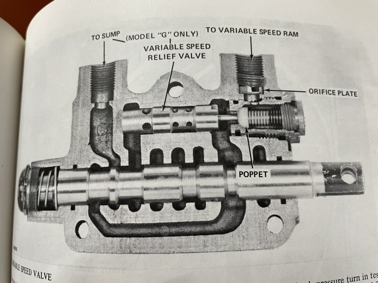 Here is a cut away picture of the valve in question…oil is supplied and returned through the same port on the valve…the port labeled “TO VARIABLE SPEED RAM”…how is the return oil supposed to get past the poppet?
Edited by Oldoug - 09 Jan 2024 at 11:36pm
|
|
Matt Folkers
FOLKERS RESTORATION
Restoring vintage things to last so the future can enjoy our past.
|
|
AC7060IL
Orange Level
Joined: 19 Aug 2012
Location: central IL
Points: 3582
|
Post Options
Thanks(0)
Quote Reply
Posted: 10 Jan 2024 at 12:04am |
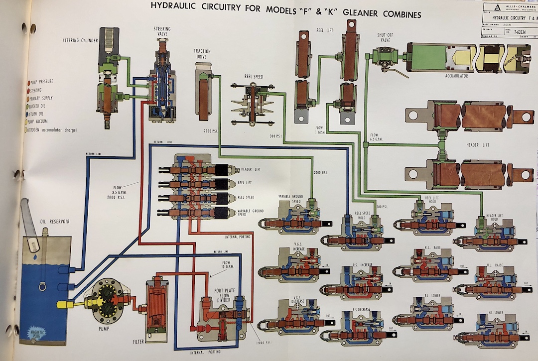 So you have an AC Gleaner Service Manual? I do too. Maybe you haven't found it's hydraulic circuitry fold-out near the back of the manual? If not, here is a copy of my gleaner K/F hydraulic circuitry that shows the functionality of each component. It shows by colors how the Variable Speed Valve's internals function. In that same service manual's hydraulic section, try going to page 7 where it discusses in detail how the variable speed valve(VSV) operates. It appears that you've addressed most every other avenue per your A2's hydraulic restoration? So my guess is that some item(s) within your VSV are either worn out, absent, or incorrectly placed? Hoping the above illustration helps you? You do restoration right? So do you have multiple gleaners setting about? If so, then remove an UN-touched VSV from one of parts machines & insert it into this A2's hyd system & see what happens. If that corrects the problem & you want to know whats up with this problematic VSV, carefully disassemble them both & compare.
Edited by AC7060IL - 10 Jan 2024 at 12:34am
|
|
Oldoug
Orange Level Access
Joined: 12 Sep 2009
Points: 1139
|
Post Options
Thanks(0)
Quote Reply
Posted: 10 Jan 2024 at 12:33am |
|
Thank you for this color breakdown schematic…this is what I have been hoping and looking for all along is some information on how the oil flows through these valves.
|
|
Matt Folkers
FOLKERS RESTORATION
Restoring vintage things to last so the future can enjoy our past.
|
|
im4racin
Orange Level
Joined: 12 Jun 2017
Location: Garrison ND
Points: 1079
|
Post Options
Thanks(0)
Quote Reply
Posted: 10 Jan 2024 at 6:09am |
|
Sorry I missed the feeder house bit. The pressure relief valve in your black and white pic is a little misleading. It's more of a pressure bleed off spool. It appears to be pilot operated to push the poppet.
|
|