| Author |
 Topic Search Topic Search  Topic Options Topic Options
|
dfwallis 
Orange Level

Joined: 09 Mar 2023
Location: DFW
Points: 892
|
 Post Options Post Options
 Thanks(0) Thanks(0)
 Quote Quote  Reply Reply
 Topic: CA "New Design" Top Link Bracket Mods Topic: CA "New Design" Top Link Bracket Mods
Posted: 26 Jun 2023 at 1:27pm |
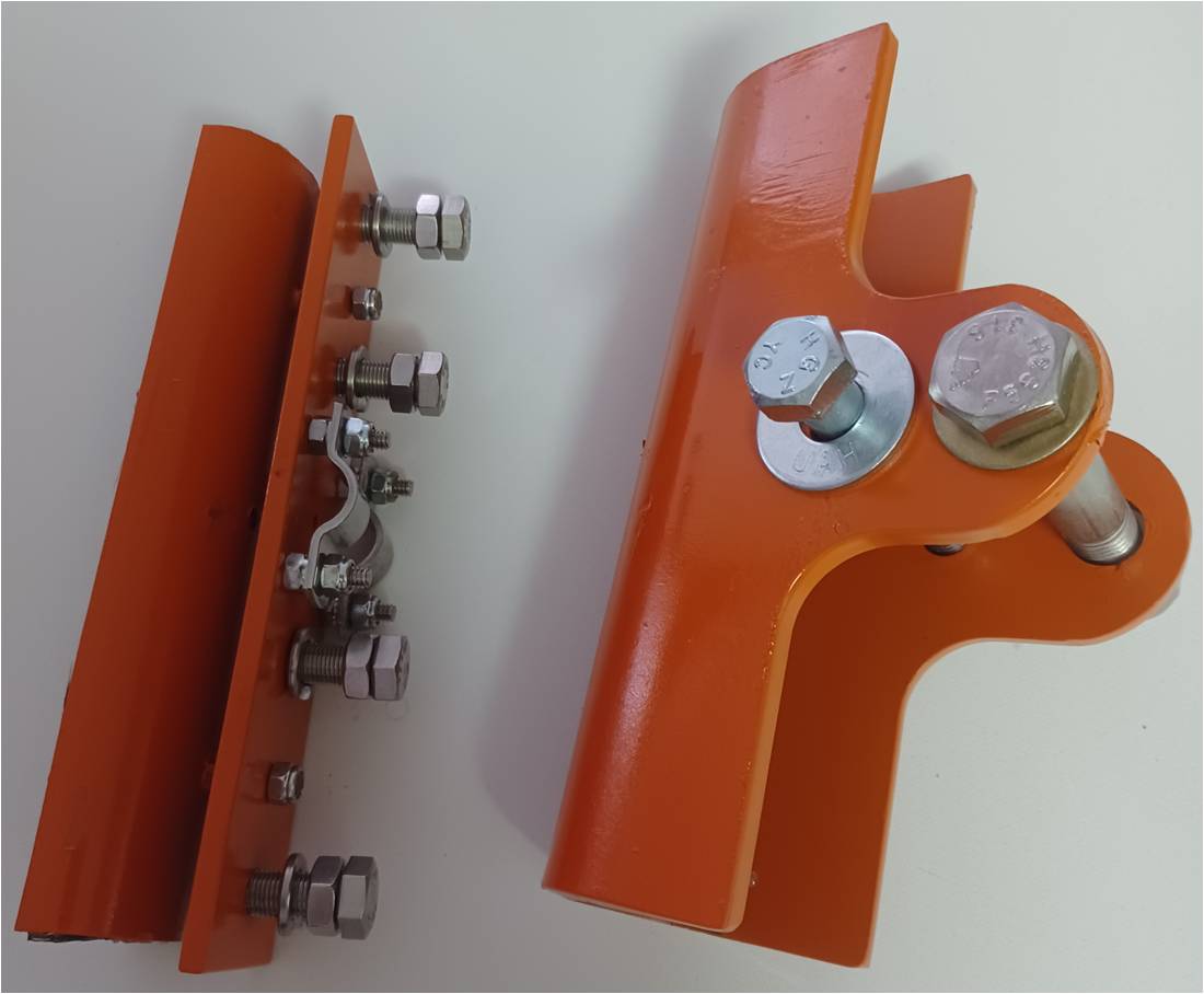
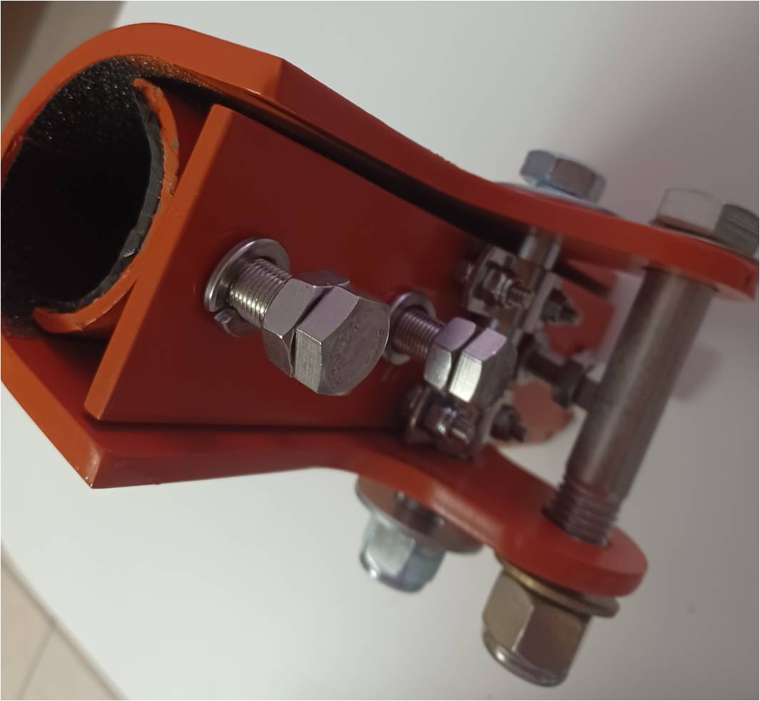
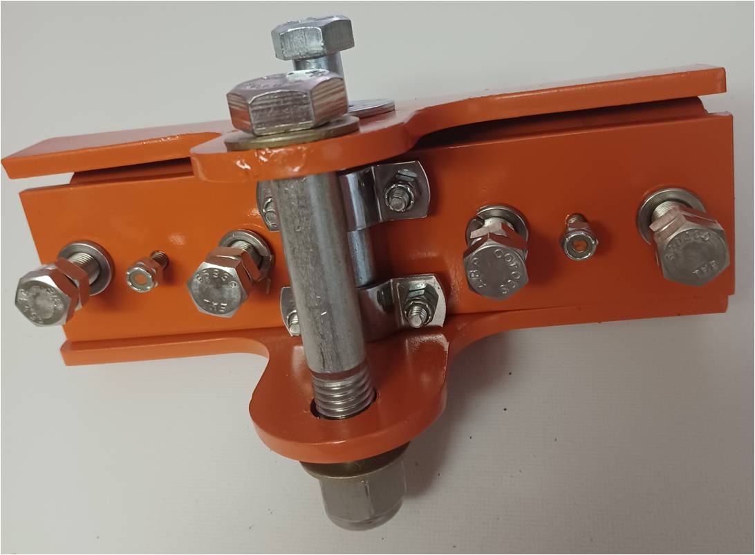
I was really happy with the "new design" CA top link bracket design, but there are a few issues that I wanted to address. For one, it seems to be designed for a larger diameter rockshaft than the CA rockshaft so there would be quite a lot of movement slop. So, I've developed a clamping mechanism that should work reasonably well. I don't think I can generate enough clamping force to absolutely prevent rotation under load, but at least it won't just flop around. It consists of a flat plate that pushes against the inner bolt of the bracket and in front of that is a loosely coupled half round clamp section. Clamping force is applied with 4 fine threaded half inch bolts with lock nuts/washers. Because the new bracket design is very wide, the clamping force should be reasonably good. I didn't have a nice butyl insert so I made one out of an inner tube. It didn't want to comply/conform very well. The second issue is that I want the top link bolt/pin pattern to be horizontal. I'm still waiting for parts to finish that bracket adaptor design.
 |
 |
|
Sponsored Links
|
|
 |
dfwallis 
Orange Level

Joined: 09 Mar 2023
Location: DFW
Points: 892
|
 Post Options Post Options
 Thanks(0) Thanks(0)
 Quote Quote  Reply Reply
 Posted: 28 Jun 2023 at 4:56pm Posted: 28 Jun 2023 at 4:56pm |
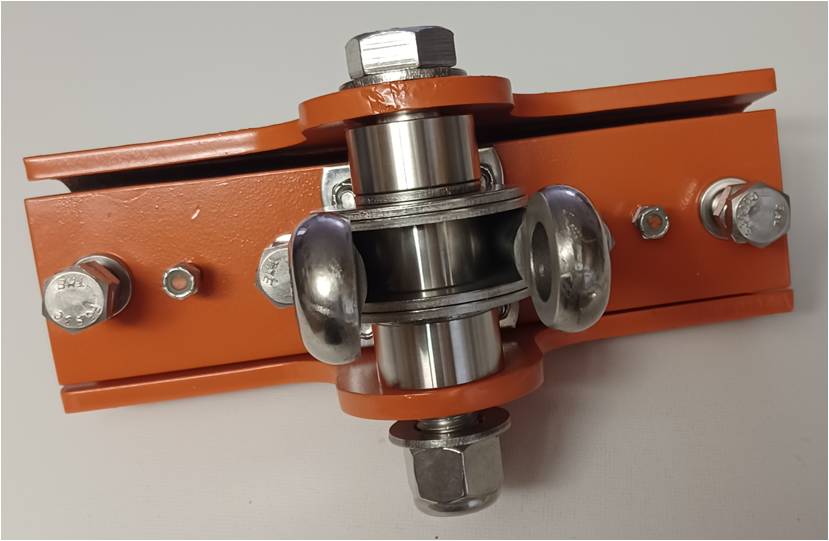
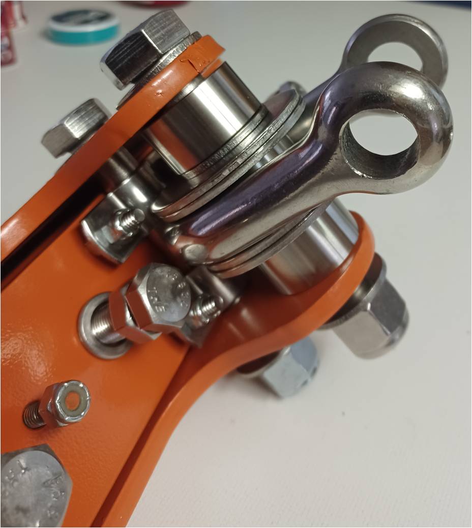
Here is the adaptor modification for attaching the top link horizontally instead of vertically (which aligns with the natural orientation and range of motion of the top link itself). Basically it's a D shackle with spacers to adjust its position and range of motion. We'll see how it works :). I really dislike machining stainless steel, but mods were necessary to the D shackle :(
Edited by dfwallis - 28 Jun 2023 at 6:36pm
|
 |
steve(ill) 
Orange Level Access


Joined: 11 Sep 2009
Location: illinois
Points: 88672
|
 Post Options Post Options
 Thanks(0) Thanks(0)
 Quote Quote  Reply Reply
 Posted: 28 Jun 2023 at 6:19pm Posted: 28 Jun 2023 at 6:19pm |
What problems did you have with the bracket rotating on the rock shaft ??
a lot of nice QUALITY work went into that !!!
Edited by steve(ill) - 28 Jun 2023 at 6:21pm
|
|
Like them all, but love the "B"s.
|
 |
dfwallis 
Orange Level

Joined: 09 Mar 2023
Location: DFW
Points: 892
|
 Post Options Post Options
 Thanks(0) Thanks(0)
 Quote Quote  Reply Reply
 Posted: 28 Jun 2023 at 6:26pm Posted: 28 Jun 2023 at 6:26pm |
 steve(ill) wrote: steve(ill) wrote:
What problems did you have with the bracket rotating on the rock shaft ??
a lot of nice QUALITY work went into that !!! |
The CA rockshaft is only 1 and 7/8ths diameter. This bracket is designed for a 2.5 inch rockshaft. There's no possibility of tightening. You'd have to nearly pinch the two halves of the outer tab together to have any hope of clamping to the rockshaft. The bracket is thick alloy steel. I think you'd come close to stripping the 5/8 bolt if you tried to clamp down that much while in the process deforming the bracket to the point that the top link wouldn't attach. So, there's no doubt there would be quite a bit of side to side motion slop in addition to it being 100% free to rotate. That may or may not be a problem in some real connections, but I just didn't like it.
|
 |
JimD 
Orange Level

Joined: 11 Sep 2009
Location: Mounds, OK
Points: 2116
|
 Post Options Post Options
 Thanks(0) Thanks(0)
 Quote Quote  Reply Reply
 Posted: 29 Jun 2023 at 1:56pm Posted: 29 Jun 2023 at 1:56pm |
|
Very nice work. I designed the bracket you started with and it was actually made for the wd and wd45. So the CA does have more slop. The manufacturer was willing to make what you have but not any other improvements. Having sold them for 20+ years the only problems we ran into were an auger that had to have a horizontal pin and some that did plowing and pushed on the bracket in use. Any lifting pulled the bracket and the slop didn't cause any problems. It's been a battle to keep the prices down and your work is terrific, but would be very expensive for our customers.
|
Owner of OKtractor.com PM for an instant response on parts. Open M-F 9-6 Central. We have new and used parts. 877-378-6543
|
 |
dfwallis 
Orange Level

Joined: 09 Mar 2023
Location: DFW
Points: 892
|
 Post Options Post Options
 Thanks(0) Thanks(0)
 Quote Quote  Reply Reply
 Posted: 29 Jun 2023 at 3:47pm Posted: 29 Jun 2023 at 3:47pm |
 JimD wrote: JimD wrote:
Very nice work. I designed the bracket you started with and it was actually made for the wd and wd45. So the CA does have more slop. The manufacturer was willing to make what you have but not any other improvements. Having sold them for 20+ years the only problems we ran into were an auger that had to have a horizontal pin and some that did plowing and pushed on the bracket in use. Any lifting pulled the bracket and the slop didn't cause any problems. It's been a battle to keep the prices down and your work is terrific, but would be very expensive for our customers. |
Thanks, I'd say my design cost on the order of what the original bracket cost, not including my labor :) :(. On the other hand, I used stainless steel for all the fasteners, so that drove up the cost a little. This may well be the most expensive CA renovation in history :)
|
 |
dfwallis 
Orange Level

Joined: 09 Mar 2023
Location: DFW
Points: 892
|
 Post Options Post Options
 Thanks(0) Thanks(0)
 Quote Quote  Reply Reply
 Posted: 29 Jun 2023 at 4:02pm Posted: 29 Jun 2023 at 4:02pm |
|
I'm also working on a new bail system for a 1952 pin hitch drawbar. It will mount to the cultivator brackets. So far, just the raw flats, roughly equivalent to the metal in the 3pt hitch kits, cost more than the entire 3pt hitch kit :( And that's for 1018 not the alloy steel used in the kits. Those metalsupermarkets have a huge markup it appears.
|
 |
BillinAlberta 
Silver Level


Joined: 12 Sep 2009
Location: Saskatchewan
Points: 358
|
 Post Options Post Options
 Thanks(1) Thanks(1)
 Quote Quote  Reply Reply
 Posted: 29 Jun 2023 at 7:43pm Posted: 29 Jun 2023 at 7:43pm |
|
Man that is a work of art!
|
 |


 Topic Options

 Post Options
 Thanks(0)



 steve(ill) wrote:
