| Author |
 Topic Search Topic Search  Topic Options Topic Options
|
D17SeriesIV 
Silver Level


Joined: 26 Jan 2015
Location: Hartwell, GA
Points: 82
|
 Post Options Post Options
") Thanks(0) Thanks(0)
 Quote Quote  Reply Reply
 Topic: D17, better suited for Cat I, or Cat II? Topic: D17, better suited for Cat I, or Cat II?
Posted: 04 Feb 2015 at 8:27am |
|
I'll apologize up front for so many 3 pt questions, just trying to hammer out what I should be shooting for realistically.
So, on my Series II D17 the lift arms are 32" apart (width) which would line up great for Cat II lower arms. But, my top link pin is 18" above the drawbar, so that puts the pin height perfect for Cat I.
My question being, would it be feasible, or worth the effort to set it up as Cat I/II?
My less than mediocre thinking, is raising the top link mount would be easy to do while keeping my current mount available via an overbuilt bracket. The lower arms, would be simple enough to accommodate with some really adjustable stabilizers and a ball joint on each end of the arm.
I'm sure there is a prefab kit, or whole setup that would avoid these questions. An even easier answer, would be to check the implements available to me to see if they're Cat I or Cat II. All that aside, I'd still prefer to build it to suit all my needs from the beginning. Also, as mentioned before, it's becoming a family project so anything other than shop built is going to nullify the fun of it. Granted, yes, the ball joints, maybe the adjusters and definitely the top link will be store bought, but the lower arms, etc., will be shop built (helps that it's a family full of professional welders too)
In all honesty, I'm looking for pointers and pitfalls to avoid from others that have built their own 3 pt setup on the D17. Thanks in advance, and for the countless questions answered by searching the forum here as well!
|
 |
|
Sponsored Links
|
|
|
Gatz in NE
Orange Level

Joined: 11 Sep 2009
Location: Lincoln, NE
Points: 1043
|
Post Options
Thanks(0)
Quote Reply
Posted: 04 Feb 2015 at 9:43am |
|
CAT II
|
|
JoeO(CMO)
Orange Level

Joined: 11 Sep 2009
Location: Cent Missouri
Points: 2694
|
Post Options
Thanks(0)
Quote Reply
Posted: 04 Feb 2015 at 9:55am |
|
Cat 2, because of horsepower and weight.
Cat 1 was border line for D15 II
|
|
|
|
D17SeriesIV
Silver Level
Joined: 26 Jan 2015
Location: Hartwell, GA
Points: 82
|
Post Options
Thanks(0)
Quote Reply
Posted: 04 Feb 2015 at 10:38am |
|
Thanks fellas! I figured that was the case, but wanted to make sure. There's a lot more misinformation readily available out on the "inter-web" than good info. Hence the reason I bug y'all with questions so often.
Thanks again!
|
|
Mactractor
Orange Level Access

Joined: 20 Jun 2011
Location: New Zealand
Points: 652
|
Post Options
Thanks(0)
Quote Reply
Posted: 04 Feb 2015 at 12:51pm |
|
Use Cat 2 balls on the end of your draught arms. If you then want to latch onto something with cat 1 trunnion pins, use the step up bushings. You cant do that the other way round. There is only 1" difference in height for top link between 1 and 2
|
|
Dgrader
Orange Level

Joined: 17 Jan 2015
Location: Newton,IL
Points: 1037
|
Post Options
Thanks(0)
Quote Reply
Posted: 04 Feb 2015 at 7:11pm |
|
If ya want to know anything about ALLIS. This is the place to be.
|
|
JoeO(CMO)
Orange Level
Joined: 11 Sep 2009
Location: Cent Missouri
Points: 2694
|
Post Options
Thanks(0)
Quote Reply
Posted: 05 Feb 2015 at 7:24am |
|
If you put a Cat I on a D17 it is much easier to form(bend) the draft arms to your situation!!
|
|
|
|
Gerald J.
Orange Level
Joined: 12 Sep 2009
Location: Hamilton Co, IA
Points: 5636
|
Post Options
Thanks(0)
Quote Reply
Posted: 05 Feb 2015 at 10:13am |
|
A lot depends on the weight of the tractor and the weight balance affected by the distance the implement is behind the rear wheels. Cat II implements tend to be bigger and heavier. You can't plant controlled when the front wheels are just barely touching the ground. You can't rotary how or cultivate either without the guidance from good front wheel contact. Been there, done that with a MF-135. Front end weighting was crucial, but I loaded up a 6 row JD cultivator and a 15' JD rotary hoe that way. I made the lift pins on my lathe for those. When I loaded my three point sprayer filled with 32% N and hitched my planter on the draw bar I had to find all the front weight I could hang on to plant with better control than the rear brakes and take out half the 32% which meant refreshing that tank every 2 acres.
In good farm stores there are cat I pins with cat II mounts. So it is practical to change the implements. And then there are sleeves or bushings to center cat 1 pins in cat II lift arms and top links. And there are double ended lift pins cat II on the fat end and cat I on the thin end so they can be mounted with the cat II pins outside the implement frame and cat I inside and be handy for both widths of lift arms. For examples of what is available, look at pages C2 through C4 of the catalog section C at Baum Hydraulics. www.baumhydraulics.com The prices are their suggested retail prices, they sell for less. Look for DATE on the page, the number following DATE is 100 times the trade discount in %, e.g. DATE 2000 means 20% discount on the price they sell for.
If the top link height on the tractor is shorter than the tower on the implement, the implement will tilt forward when raised which usually isn't a great problem. If the relation is reversed, lower on the implement then the back of the implement won't lift as much as the front as it tilts back and that's often not so great.
Fundamentally the choice of implement hitch and implement choice has to depend on tractor front weight, tractor lift capability, and implement weight.
Gerald J.
|
|
DaveKamp
Orange Level Access
Joined: 12 Apr 2010
Location: LeClaire, Ia
Points: 5937
|
Post Options
Thanks(0)
Quote Reply
Posted: 05 Feb 2015 at 10:50pm |
Here's the way I did it: 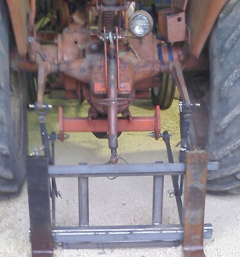 Category II. I used off-the-shelf arms, lift links, and top link, as well as pins. Bottom assembly a heavy-wall tubing with 1" thick square plate ends. Top link bracket should be fairly obvious...
|
|
Ten Amendments, Ten Commandments, and one Golden Rule solve most every problem. Citrus hand-cleaner with Pumice does the rest.
|
|
D17SeriesIV
Silver Level
Joined: 26 Jan 2015
Location: Hartwell, GA
Points: 82
|
Post Options
Thanks(0)
Quote Reply
Posted: 28 Feb 2015 at 4:02pm |
|
I like that setup. Just curious, (as this has been the only part I can't quite figure out) Where is the mount for the lower arms mounted? All the pics I find block where/how that part is mounted.
|
|
DaveKamp
Orange Level Access
Joined: 12 Apr 2010
Location: LeClaire, Ia
Points: 5937
|
Post Options
Thanks(0)
Quote Reply
Posted: 28 Feb 2015 at 9:39pm |
|
You mean the 5" square tube? It's welded directly to the brackets that originally suspended the drawbar. I took them off, beveled the areas to be welded, then put 'em back on lightly, lifted the cross-tube assembly up with a floor jack, tapped it into position with a mallet, measured, tapped, measured... then tacked the pieces together, removed the whole works, and finish-welded it on the welding table.
The square tubing is high up enough so that the original drawbar still works just fine.
|
|
Ten Amendments, Ten Commandments, and one Golden Rule solve most every problem. Citrus hand-cleaner with Pumice does the rest.
|
|
DSeries4
Orange Level

Joined: 12 Sep 2009
Location: Ontario, Canada
Points: 7428
|
Post Options
Thanks(0)
Quote Reply
Posted: 01 Mar 2015 at 9:29am |
|
No offense Dave, but I have a couple of concerns with your set up.
With it bolted up where the drawbar hanger goes, the pull point is set up higher and further back which can affect the balance of the tractor (especially when plowing or heavy pulling). I do not think that area was designed to be a pull point either (it only holds up the drawbar).
I think a setup that hooks directly to the snap coupler would be the best. My dad made one 30 years ago - worked great and the traction booster was still able to function.
|
|
'49 G, '54 WD45, '55 CA, '56 WD45D, '57 WD45, '58 D14, '59 D14, '60 D14, '61 D15D, '66 D15II, '66 D21II, '67 D17IV, '67 D17IVD, '67 190XTD, '73 620, '76 185, '77 175, '84 8030, '85 6080
|
|
John (MO)
Orange Level
Joined: 16 Sep 2009
Location: NEMO
Points: 202
|
Post Options
Thanks(0)
Quote Reply
Posted: 01 Mar 2015 at 12:34pm |
|
Why would anyone build something that eliminated the function of the traction booster?
|
|
Jim Lindemood
Orange Level

Joined: 22 Sep 2009
Location: Dry Ridge, KY
Points: 2569
|
Post Options
Thanks(0)
Quote Reply
Posted: 01 Mar 2015 at 2:14pm |
|
Different strokes for different folks -- makes the world go around - If it works for you, carry on.
|
|
DougS
Orange Level

Joined: 03 Nov 2011
Location: Iowa
Points: 2490
|
Post Options
Thanks(0)
Quote Reply
Posted: 01 Mar 2015 at 3:00pm |
|
That setup will work fine for what is shown. Add me to the list of those who wouldn't use it for pulling with a drawbar connected across the lift arms. The tractor is more stabile when pulling from a spot lower and in front of the rear axle. With mounted equipment it won't matter so much.
|
|


