| Author |
 Topic Search Topic Search  Topic Options Topic Options
|
dfwallis 
Orange Level

Joined: 09 Mar 2023
Location: DFW
Points: 892
|
 Post Options Post Options
") Thanks(0) Thanks(0)
 Quote Quote  Reply Reply
 Topic: CA Hydraulic Pump Direct Output Access? Topic: CA Hydraulic Pump Direct Output Access?
Posted: 25 Jul 2023 at 8:38pm |
|
Does anyone know if there is an access port pre-control valve on the CA hydraulic pump? Some pictures seem to show a plugged outlet, but none show it clearly that I can find and it's hard for me to interpret the images that I can find. And of course I can't tell if it's before or after the control valve.
|
 |
|
Sponsored Links
|
|
|
MACK
Orange Level
Joined: 17 Nov 2009
Points: 7664
|
Post Options
Thanks(0)
Quote Reply
Posted: 25 Jul 2023 at 8:49pm |
|
What are you trying to do? All oil goes into hold position valve and out. MACK
|
|
DrAllis
Orange Level Access
Joined: 12 Sep 2009
Points: 22180
|
Post Options
Thanks(0)
Quote Reply
Posted: 25 Jul 2023 at 8:50pm |
|
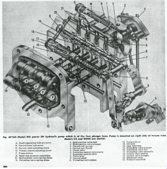
What are you attempting to do ????? If you removed the HOLD valve assembly from the top of the hydraulic pump's main body, you'd see one hole. That hole is where the pressurized oil comes from and returns to, WHEN you activate the lift/lower lever on the pump that turns the pump ON or shuts it OFF.
|
|
dfwallis
Orange Level
Joined: 09 Mar 2023
Location: DFW
Points: 892
|
Post Options
Thanks(0)
Quote Reply
Posted: 25 Jul 2023 at 9:13pm |
 DrAllis wrote: DrAllis wrote:
What are you attempting to do ????? If you removed the HOLD valve assembly from the top of the hydraulic pump's main body, you'd see one hole. That hole is where the pressurized oil comes from and returns to, WHEN you activate the lift/lower lever on the pump that turns the pump ON or shuts it OFF. |
I want to run a parallel line to a new circuit of spools with a shutoff valve and a pressure limit relief valve for double acting cylinders. No technical reason that won't work if there is access to the raw pump output that feeds the CA control valve.
|
|
DrAllis
Orange Level Access
Joined: 12 Sep 2009
Points: 22180
|
Post Options
Thanks(0)
Quote Reply
Posted: 25 Jul 2023 at 9:23pm |
|
But, if you simply plug in to the remote coupler with a implement hose end and pull clear up on the hydraulic lever, oil will flow out of the coupler to your valve stack.
|
|
dfwallis
Orange Level
Joined: 09 Mar 2023
Location: DFW
Points: 892
|
Post Options
Thanks(0)
Quote Reply
Posted: 26 Jul 2023 at 11:36am |
DrAllis wrote:
But, if you simply plug in to the remote coupler with a implement hose end and pull clear up on the hydraulic lever, oil will flow out of the coupler to your valve stack. |
Well, of course, but then I have to have the 3 pt in the up position in order to control the other circuits. I don't want that.
|
|
steve(ill)
Orange Level Access
Joined: 11 Sep 2009
Location: illinois
Points: 88661
|
Post Options
Thanks(0)
Quote Reply
Posted: 26 Jul 2023 at 12:50pm |
Gary, you could use a splitter valve on the hose OUT of your hydraulic valve to the 3 point cylinder.. In ONE position, your hydraulic valve and 3 point would work normal and the 2 way cylinders would be locked out.......... in the SECOND position, the 3 point would be locked out, and you would pin your hydraulic valve/ pump to send oil to your 2 way cylinder valve CONTINUOUSLY..... of course you need a Return Hose for the 2 way system.
Thats about the best you can do on the CA....... It is very common as Dr said, to raise the 3 point, clip on a chain to hold it there, then run you 2 way cylinders with the original tractor valve WIDE OPEN......... again, you need a Return hose for the 2 way valve.
Edited by steve(ill) - 26 Jul 2023 at 12:51pm
|
|
Like them all, but love the "B"s.
|
|
dfwallis
Orange Level
Joined: 09 Mar 2023
Location: DFW
Points: 892
|
Post Options
Thanks(0)
Quote Reply
Posted: 26 Jul 2023 at 1:06pm |
steve(ill) wrote:
Gary, you could use a splitter valve on the hose OUT of your hydraulic valve to the 3 point cylinder.. In ONE position, your hydraulic valve and 3 point would work normal and the 2 way cylinders would be locked out.......... in the SECOND position, the 3 point would be locked out, and you would pin your hydraulic valve/ pump to send oil to your 2 way cylinder valve CONTINUOUSLY..... of course you need a Return Hose for the 2 way system.
Thats about the best you can do on the CA....... It is very common as Dr said, to raise the 3 point, clip on a chain to hold it there, then run you 2 way cylinders with the original tractor valve WIDE OPEN......... again, you need a Return hose for the 2 way valve.
|
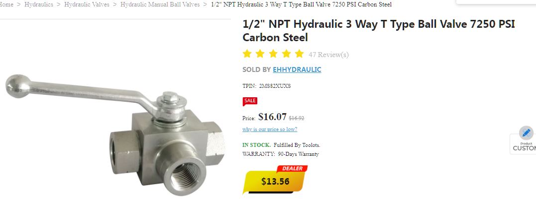
My goal is to keep the existing system intact and operational as-is. If I'm forced to add a second pump (/reservoir), I will. I've purchased the new spools/valves, a shutoff, and a pressure regulator to limit to 2500 (adjustable 50-5000psi, or whatever the cylinders need). I know I'll have to run a new return (somehow). My thought was that in the operational state, the new spools would reduce the lift capacity of the 3 point because it would shunt to return at 2500psi, so when I need maximum 3pt lift, I'd have to shut the new circuit off. The shutoff valve I bought looks like the same brand as above :) I also may be able to convert one of the new spools to behave like a single acting control. But its a ganged group and no way to keep 3200psi on one and 2500psi on the others (without more regulators on each output).
|
|
steve(ill)
Orange Level Access
Joined: 11 Sep 2009
Location: illinois
Points: 88661
|
Post Options
Thanks(0)
Quote Reply
Posted: 26 Jul 2023 at 1:23pm |
I dont see a good way to do that with just the factory pump... The pump puts out oil CONSTANTLY...back to sump at no pressure. When you stroke the valve, it shuts off the sump drain and puts PRESSURE oil to the output port (hose)... dont see a good way to get INBETWEEN that..
|
|
Like them all, but love the "B"s.
|
|
tadams(OH)
Orange Level Access

Joined: 17 Sep 2009
Location: Jeromesville, O
Points: 11037
|
Post Options
Thanks(0)
Quote Reply
Posted: 26 Jul 2023 at 1:42pm |
|
Your better off adding another hydralic pump and reservoir
|
|
MACK
Orange Level
Joined: 17 Nov 2009
Points: 7664
|
Post Options
Thanks(0)
Quote Reply
Posted: 26 Jul 2023 at 10:11pm |
|
Add a new system, using old pump will be too slow for most jobs. MACK
|
|
dfwallis
Orange Level
Joined: 09 Mar 2023
Location: DFW
Points: 892
|
Post Options
Thanks(0)
Quote Reply
Posted: 27 Jul 2023 at 10:55am |
MACK wrote:
Add a new system, using old pump will be too slow for most jobs. MACK |
Similar conversions have been done on WDs with good results. As long as the cylinder is around 2 inch bore or smaller, performance should be reasonably good. I'm considering several options, including a separate pump. I may initially attempt to get a single acting spool valve that mimics the existing CA valve (effectively, center detent closed to hold position, and reverse actuation return to tank to allow gravity bled lowering). That way I can separate the single and double acting circuits since I'll have full access external to the pump (i.e. use the existing pump output full on routed to the new circuits).
|
|
dfwallis
Orange Level
Joined: 09 Mar 2023
Location: DFW
Points: 892
|
Post Options
Thanks(0)
Quote Reply
Posted: 27 Jul 2023 at 6:40pm |
dfwallis wrote:
MACK wrote:
Add a new system, using old pump will be too slow for most jobs. MACK |
Similar conversions have been done on WDs with good results. As long as the cylinder is around 2 inch bore or smaller, performance should be reasonably good. I'm considering several options, including a separate pump. I may initially attempt to get a single acting spool valve that mimics the existing CA valve (effectively, center detent closed to hold position, and reverse actuation return to tank to allow gravity bled lowering). That way I can separate the single and double acting circuits since I'll have full access external to the pump (i.e. use the existing pump output full on routed to the new circuits). |
While I can find 3-way/single acting control valves with the correct functionality, they either top out at 2500psi working pressure or they want 2 grand for them :(
Edited by dfwallis - 27 Jul 2023 at 6:40pm
|
|
steve(ill)
Orange Level Access
Joined: 11 Sep 2009
Location: illinois
Points: 88661
|
Post Options
Thanks(0)
Quote Reply
Posted: 27 Jul 2023 at 7:17pm |
you plumb it up so the FACTORY pump uses the internal pressure setting of 3200 psi... If you run the pump to a NEW VALVE and it has a 2500 psi setting, thats all the pressure you will get.. You will not get 3200 psi to the NEW VALVE...... but you have to have an ISOLATION valve or 3 way valve between the two systems so only ONE is working at a time.
OR... get a new STACK VALVE and run the hose to it... then use ONE of the valve sections to run your 3 point and a different spool to run the new 2 inch cylinder.... you have to make sure that ONE of the valve spools in the NEW STACK is capable of power UP and FLOAT down..... and the other is power UP and DOWN and center neutral.... im guessing 2500 psi would be enough for MOST of the 3 point lifts ?
Edited by steve(ill) - 27 Jul 2023 at 7:19pm
|
|
Like them all, but love the "B"s.
|
|
dfwallis
Orange Level
Joined: 09 Mar 2023
Location: DFW
Points: 892
|
Post Options
Thanks(0)
Quote Reply
Posted: 27 Jul 2023 at 7:34pm |
steve(ill) wrote:
you plumb it up so the FACTORY pump uses the internal pressure setting of 3200 psi... If you run the pump to a NEW VALVE and it has a 2500 psi setting, thats all the pressure you will get.. You will not get 3200 psi to the NEW VALVE...... but you have to have an ISOLATION valve or 3 way valve between the two systems so only ONE is working at a time.
OR... get a new STACK VALVE and run the hose to it... then use ONE of the valve sections to run your 3 point and a different spool to run the new 2 inch cylinder.... you have to make sure that ONE of the valve spools in the NEW STACK is capable of power UP and FLOAT down..... and the other is power UP and DOWN and center neutral.... im guessing 2500 psi would be enough for MOST of the 3 point lifts ?
|
That's what I've been saying. But the 3-way valve can operate at the full 3200psi (if I can find one). The dual acting valves will have a pressure limiting relief valve ahead of them that shunts to tank at whatever pressure I dial in.
|
|
steve(ill)
Orange Level Access
Joined: 11 Sep 2009
Location: illinois
Points: 88661
|
Post Options
Thanks(0)
Quote Reply
Posted: 27 Jul 2023 at 7:56pm |
what do you do with the 3 point ? There is a good chance that the 2500 psi would be enough for most applications.. Put a TEE and gauge in the hose and see what the pressure is when you LIFT whatever you are lifting..
another option to simplify things is to replace the 3 point lift cylinder with a 1/2 inch larger diameter cylinder.. then use the 2500 PSI and have the same LIFT Force.
Edited by steve(ill) - 27 Jul 2023 at 7:59pm
|
|
Like them all, but love the "B"s.
|
|
dfwallis
Orange Level
Joined: 09 Mar 2023
Location: DFW
Points: 892
|
Post Options
Thanks(0)
Quote Reply
Posted: 28 Jul 2023 at 12:04pm |
steve(ill) wrote:
what do you do with the 3 point ? There is a good chance that the 2500 psi would be enough for most applications.. Put a TEE and gauge in the hose and see what the pressure is when you LIFT whatever you are lifting..
another option to simplify things is to replace the 3 point lift cylinder with a 1/2 inch larger diameter cylinder.. then use the 2500 PSI and have the same LIFT Force. |
The additional, external single acting spool will be used for the 3 point. The CA pump output will feed the external circuit only, not the existing CA actuator circuit/remote. The new external SA spool will allow me to have both a single acting circuit (connected to the original CA cylinders and remote) and a double acting circuit. I will try to design it so that I can easily redirect the CA pump output back to the original cylinder/remote circuit with a selector valve. I intend to not have dozens of permanent hoses routed, but instead have quick disconnects everywhere and only connect what's needed for the particular implement(s). I plan on 4 sets of remotes on each of the 4 corners of the platform. The design will also very easily adapt to a separate pump, if I decide that is necessary. I've purchased a dual pulley for the generator (5/8 inch belt) but was warned by the generator rebuilder guy that that might put too much stress on the rear generator sleeve bearing. The front sleave bearing was replaced with a ball bearing so should be fine. Hopefully, I won't need to tighten the belt too much for a small 11gpm-ish pump with a 5/8 inch belt. And I might be able to pull slightly in a direction that counters the generator drive belt, reducing stress. I won't purchase a pump though until I decide its necessary. I did research some with electric clutches that I liked. Easy to create a 6v to 12v circuit to control it.
|
|
dfwallis
Orange Level
Joined: 09 Mar 2023
Location: DFW
Points: 892
|
Post Options
Thanks(0)
Quote Reply
Posted: 28 Jul 2023 at 4:45pm |
dfwallis wrote:
The additional, external single acting spool will be used for the 3 point. The CA pump output will feed the external circuit only, not the existing CA actuator circuit/remote. The new external SA spool will allow me to have both a single acting circuit (connected to the original CA cylinders and remote) and a double acting circuit. I will try to design it so that I can easily redirect the CA pump output back to the original cylinder/remote circuit with a selector valve. I intend to not have dozens of permanent hoses routed, but instead have quick disconnects everywhere and only connect what's needed for the particular implement(s). I plan on 4 sets of remotes on each of the 4 corners of the platform. The design will also very easily adapt to a separate pump, if I decide that is necessary. I've purchased a dual pulley for the generator (5/8 inch belt) but was warned by the generator rebuilder guy that that might put too much stress on the rear generator sleeve bearing. The front sleave bearing was replaced with a ball bearing so should be fine. Hopefully, I won't need to tighten the belt too much for a small 11gpm-ish pump with a 5/8 inch belt. And I might be able to pull slightly in a direction that counters the generator drive belt, reducing stress. I won't purchase a pump though until I decide its necessary. I did research some with electric clutches that I liked. Easy to create a 6v to 12v circuit to control it. |
I did finally find a suitable SA valve. Really difficult to find one (3 way) with all the right characteristics. Bailey/Chief brand. Finger's crossed...I actually found it on a reseller website but when I opened the technical specifications document they had for it, it listed different specs so I didn't trust the listing.
|
|
DaveKamp
Orange Level Access
Joined: 12 Apr 2010
Location: LeClaire, Ia
Points: 6091
|
Post Options
Thanks(0)
Quote Reply
Posted: 29 Jul 2023 at 11:56am |
This is the classic scenario where a legacy low-volume/high pressure system exists, but the device you want to power is of the high-volume/low pressure variety.
The circumstance you face isn't just a volume/pressure loading mismatch, it's an operational mismatch because the pump is designed from the git-go to be the heart of a LIFT system, not a 'power take-off' system. It has integral unloading when pressure limit is reached AND when the load cycle is cut off. It also has a volumetric limitation to the supply reservoir, and you'll likely bounce off that limit regularly... there just isn't a whole lot of reservoir volume available. you'll have a pair of LP/HV lift cylinders.. you can alleviate SOME of this by employing the BACK side of the cylinders as available reservoir volume...
Finally, it's not 'live' in the respect of always-available-output... you need to engage it to operate, and if you depress the foot clutch, the pump stops.
The concern about generator/alternator dual-sheave is very valid. The proper term is 'overhanging load'... tension on the belt causes shaft side-load, and the further the line of force from the generator bushing, the more leverage your loading is on the bushing, not just from an extra pump, but the simple fact that you have the generator's original drive load, and yet-another-drive-load coupled. All those factors compound the overhanging load, and you really don't want that limitation.
There's many ways to get around these problems, and the very best is to add a complete secondary hydraulic system driven off the crank.
Overhanging load is not good for hydraulic pumps, but the CA's layout doesn't leave a whole heckuva lotta room to tuck a hydraulic PUMP in line with the crank... at least, not without putting the pump on a bracket out front of the bolster/pedestal and reaching through what USED to be the hand-crank's designated access point.
One can significantly reduce overhanging load by using a toothed belt... like a Carlisle RPP or Gates PolyChain... they require very little preload. IF you can get a drive appendage off the side of the original pump's location, you could convert the whole tractor to low-pressure/high vol by driving off the original shaft and say... an enclosed dual-row chain on a pair of sturdy bearings...
|
|
Ten Amendments, Ten Commandments, and one Golden Rule solve most every problem. Citrus hand-cleaner with Pumice does the rest.
|
|
dfwallis
Orange Level
Joined: 09 Mar 2023
Location: DFW
Points: 892
|
Post Options
Thanks(0)
Quote Reply
Posted: 29 Jul 2023 at 2:09pm |
DaveKamp wrote:
This is the classic scenario where a legacy low-volume/high pressure system exists, but the device you want to power is of the high-volume/low pressure variety.
The circumstance you face isn't just a volume/pressure loading mismatch, it's an operational mismatch because the pump is designed from the git-go to be the heart of a LIFT system, not a 'power take-off' system. It has integral unloading when pressure limit is reached AND when the load cycle is cut off. It also has a volumetric limitation to the supply reservoir, and you'll likely bounce off that limit regularly... there just isn't a whole lot of reservoir volume available. you'll have a pair of LP/HV lift cylinders.. you can alleviate SOME of this by employing the BACK side of the cylinders as available reservoir volume...
Finally, it's not 'live' in the respect of always-available-output... you need to engage it to operate, and if you depress the foot clutch, the pump stops.
The concern about generator/alternator dual-sheave is very valid. The proper term is 'overhanging load'... tension on the belt causes shaft side-load, and the further the line of force from the generator bushing, the more leverage your loading is on the bushing, not just from an extra pump, but the simple fact that you have the generator's original drive load, and yet-another-drive-load coupled. All those factors compound the overhanging load, and you really don't want that limitation.
There's many ways to get around these problems, and the very best is to add a complete secondary hydraulic system driven off the crank.
Overhanging load is not good for hydraulic pumps, but the CA's layout doesn't leave a whole heckuva lotta room to tuck a hydraulic PUMP in line with the crank... at least, not without putting the pump on a bracket out front of the bolster/pedestal and reaching through what USED to be the hand-crank's designated access point.
One can significantly reduce overhanging load by using a toothed belt... like a Carlisle RPP or Gates PolyChain... they require very little preload. IF you can get a drive appendage off the side of the original pump's location, you could convert the whole tractor to low-pressure/high vol by driving off the original shaft and say... an enclosed dual-row chain on a pair of sturdy bearings...
|
I'm aware of all of these issues and designing with that in mind. I'm unconcerned about continuing to depend on the PTO circuit (hand clutch usage was never a problem for anything I needed, but who knows what the future brings). With a new pump, it should require little more than rearranging hose connections since everything will be centrally located (aside from new pump and reservoir install). I also considered a PTO shaft driven pump. A thin sprocket is already available or I could make one to suit. This would hopefully keep the PTO available (i know there are extensions for those PTO pumps that hog the whole shaft). As for the generator, again, the front shaft bushing was replaced with a ball bearing. The rear bushing won't have a huge amount of side force applied, but I believe I can leave the belt tension light with a 5/8 inch belt. If this turns out not to be the case, the pump I choose will be of a relocatable design.
Edited by dfwallis - 29 Jul 2023 at 2:24pm
|
|
dfwallis
Orange Level
Joined: 09 Mar 2023
Location: DFW
Points: 892
|
Post Options
Thanks(0)
Quote Reply
Posted: 29 Jul 2023 at 2:12pm |
dfwallis wrote:
I did finally find a suitable SA valve. Really difficult to find one (3 way) with all the right characteristics. Bailey/Chief brand. Finger's crossed...I actually found it on a reseller website but when I opened the technical specifications document they had for it, it listed different specs so I didn't trust the listing. |
I've decided to separate the single acting lift circuit from the single acting remote, so I've asked the vendor if there is a dual spool version available. If not, I'll have to buy 2 single spool versions :( Separating these will make it easier to use the wheeled disc without pinning the lift arms, although my 3pt design is intended to make doing so relatively easy.
|
|
dfwallis
Orange Level
Joined: 09 Mar 2023
Location: DFW
Points: 892
|
Post Options
Thanks(0)
Quote Reply
Posted: 29 Jul 2023 at 5:18pm |
dfwallis wrote:
DaveKamp wrote:
This is the classic scenario where a legacy low-volume/high pressure system exists, but the device you want to power is of the high-volume/low pressure variety.
The circumstance you face isn't just a volume/pressure loading mismatch, it's an operational mismatch because the pump is designed from the git-go to be the heart of a LIFT system, not a 'power take-off' system. It has integral unloading when pressure limit is reached AND when the load cycle is cut off. It also has a volumetric limitation to the supply reservoir, and you'll likely bounce off that limit regularly... there just isn't a whole lot of reservoir volume available. you'll have a pair of LP/HV lift cylinders.. you can alleviate SOME of this by employing the BACK side of the cylinders as available reservoir volume...
Finally, it's not 'live' in the respect of always-available-output... you need to engage it to operate, and if you depress the foot clutch, the pump stops.
The concern about generator/alternator dual-sheave is very valid. The proper term is 'overhanging load'... tension on the belt causes shaft side-load, and the further the line of force from the generator bushing, the more leverage your loading is on the bushing, not just from an extra pump, but the simple fact that you have the generator's original drive load, and yet-another-drive-load coupled. All those factors compound the overhanging load, and you really don't want that limitation.
There's many ways to get around these problems, and the very best is to add a complete secondary hydraulic system driven off the crank.
Overhanging load is not good for hydraulic pumps, but the CA's layout doesn't leave a whole heckuva lotta room to tuck a hydraulic PUMP in line with the crank... at least, not without putting the pump on a bracket out front of the bolster/pedestal and reaching through what USED to be the hand-crank's designated access point.
One can significantly reduce overhanging load by using a toothed belt... like a Carlisle RPP or Gates PolyChain... they require very little preload. IF you can get a drive appendage off the side of the original pump's location, you could convert the whole tractor to low-pressure/high vol by driving off the original shaft and say... an enclosed dual-row chain on a pair of sturdy bearings...
|
I'm aware of all of these issues and designing with that in mind. I'm unconcerned about continuing to depend on the PTO circuit (hand clutch usage was never a problem for anything I needed, but who knows what the future brings). With a new pump, it should require little more than rearranging hose connections since everything will be centrally located (aside from new pump and reservoir install). I also considered a PTO shaft driven pump. A thin sprocket is already available or I could make one to suit. This would hopefully keep the PTO available (i know there are extensions for those PTO pumps that hog the whole shaft). As for the generator, again, the front shaft bushing was replaced with a ball bearing. The rear bushing won't have a huge amount of side force applied, but I believe I can leave the belt tension light with a 5/8 inch belt. If this turns out not to be the case, the pump I choose will be of a relocatable design.
|
I'll add that the 72 year old generator front and rear bushings were like new, very little wear. I'm pretty sure they were not replaced or if they were, it was in the 60s.
|
|