| Author |
 Topic Search Topic Search  Topic Options Topic Options
|
siev2000 
Bronze Level

Joined: 30 Oct 2018
Location: illinois
Points: 11
|
 Post Options Post Options
") Thanks(0) Thanks(0)
 Quote Quote  Reply Reply
 Topic: 1938 model b internal timing help Topic: 1938 model b internal timing help
Posted: 06 Feb 2019 at 9:45pm |
Can anyone give me some help on a model b, nothing timing wise is working out as it should. I have a manual and nothing is lining up as it should, I suspect mix match of parts. Perhaps a phone number would be great?
thanks dustin
|
 |
|
Sponsored Links
|
|
|
CTuckerNWIL
Orange Level


Joined: 11 Sep 2009
Location: NW Illinois
Points: 22825
|
Post Options
Thanks(0)
Quote Reply
Posted: 06 Feb 2019 at 10:59pm |
First, the cam shaft has to be timed with the crankshaft by the dash marks shown here. 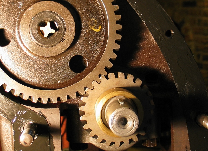
|
|
|
|
CTuckerNWIL
Orange Level
Joined: 11 Sep 2009
Location: NW Illinois
Points: 22825
|
Post Options
Thanks(0)
Quote Reply
Posted: 06 Feb 2019 at 11:04pm |
|
Where are you at with the engine? Has it been torn down? If you haven't had things apart under the timing gear cover, that should be OK.
Then all you have to do is find Top Dead Center on the COMPRESSION STROKE of number 1 cylinder. If you had the governor apart, and you have a magneto, the drive key for the magneto HAS to be horizontal when the engine is at TDC of the compression stroke on #1 cylinder.
|
|
|
|
Sugarmaker
Orange Level
Joined: 12 Jul 2013
Location: Albion PA
Points: 8661
|
Post Options
Thanks(0)
Quote Reply
Posted: 07 Feb 2019 at 8:12am |
Dustin, Welcome! Lots of knowledge here on the Model B. Take some pictures of the components and status of the engine. Help is on its way. Regards, Chris
|
|
D17 1958 (NFE), WD45 1954 (NFE), WD 1952 (NFE), WD 1950 (WFE), Allis F-40 forklift, Allis CA, Allis D14, Ford Jubilee, Many IH Cub Cadets, 32 Ford Dump, 65 Comet, 66 F100.
|
|
Gerald J.
Orange Level
Joined: 12 Sep 2009
Location: Hamilton Co, IA
Points: 5636
|
Post Options
Thanks(0)
Quote Reply
Posted: 07 Feb 2019 at 9:10am |
|
|
|
siev2000
Bronze Level
Joined: 30 Oct 2018
Location: illinois
Points: 11
|
Post Options
Thanks(0)
Quote Reply
Posted: 07 Feb 2019 at 4:45pm |
Anyone have a phone number to chat?
I have tore into this further because of the following.
When trying to set up the mag, the impulse would fire way late, roughly 20 degree atdc. Almost if the timing was a tooth off. At tdc the drive lugs for mag were off not horizontal.
I have lines on the crank and cam gear. Oval on the governor, also noticed 2 marks on the camshaft, which are not 180 from each other, more like 160. So there is no way to line up all 3 marks at once. Crank cam lined up, gov off, etc
|
|
john2189
Silver Level

Joined: 11 Sep 2009
Location: Minerva,Ohio
Points: 307
|
Post Options
Thanks(0)
Quote Reply
Posted: 07 Feb 2019 at 9:45pm |
|
Page 17 of the B-C section of the manual that Gerald posted
|
|
'41 Allis B
'45 Allis B
'49 Farmall Cub
'72 IH Cub
|
|
siev2000
Bronze Level
Joined: 30 Oct 2018
Location: illinois
Points: 11
|
Post Options
Thanks(0)
Quote Reply
Posted: 07 Feb 2019 at 10:25pm |
|
This info I need is not covered, I have that manual
|
|
Dick L
Orange Level

Joined: 12 Sep 2009
Location: Edon Ohio
Points: 5093
|
Post Options
Thanks(0)
Quote Reply
Posted: 08 Feb 2019 at 7:07am |
|
As Tucker stated above when the camshaft marks line up with the crankshaft marks as in the picture above the only other thing to worry about is that the magneto drive is horizontal. When the gear marks are matching as in the picture you are at top dead center. When the magneto drive is at the horizontal with the magneto mounted correctly the instant the crankshaft moves it trips the impulse to fire to number one plug. That is why the magneto can not be mounted at top dead center. At top dead center the magneto spring is at full load when mounted correctly.
|
|
CTuckerNWIL
Orange Level
Joined: 11 Sep 2009
Location: NW Illinois
Points: 22825
|
Post Options
Thanks(0)
Quote Reply
Posted: 08 Feb 2019 at 8:40am |
 siev2000 wrote: siev2000 wrote:
At tdc the drive lugs for mag were off not horizontal. |
If the mag drive is not horizontal at TDC, you have to pull it out and make it so. As long as you have the cam timed with the crank and the mag drive horizontal, no other marks for timing are needed. After lining up the mag drive properly, you just have to get the mag mounted so it fires on the wire you run to number 1 cylinder. That is normally set up, using the top left wire on the mag.
|
|
|
|
HoughMade
Orange Level

Joined: 22 Sep 2017
Location: Valparaiso, IN
Points: 714
|
Post Options
Thanks(0)
Quote Reply
Posted: 08 Feb 2019 at 9:48am |
How are you checking for TDC? Using the timing hole on the left side of the bellhousing and the mark on the flywheel?
If the "Center" line is in the middle of the hole (NOT the "Fire") line and both rocker arms on the #1 cylinder are loose, you are at TDC #1. If the "Center" line is in the hole, but the exhaust rocker has pressure on it, you are on TDC exhaust.
Edited by HoughMade - 08 Feb 2019 at 9:51am
|
|
1951 B
|
|
Dick L
Orange Level
Joined: 12 Sep 2009
Location: Edon Ohio
Points: 5093
|
Post Options
Thanks(0)
Quote Reply
Posted: 08 Feb 2019 at 4:44pm |
HoughMade wrote:
How are you checking for TDC? Using the timing hole on the left side of the bellhousing and the mark on the flywheel?
If the "Center" line is in the middle of the hole (NOT the "Fire") line and both rocker arms on the #1 cylinder are loose, you are at TDC #1. If the "Center" line is in the hole, but the exhaust rocker has pressure on it, you are on TDC exhaust. |
As far as timing the Crankshaft to the camshaft and then the magneto drive with the front cover off there is no need to check any other thing. Just make the magneto drive horizonal. However when the crankshaft marks are together with the camshaft the tdc or center line, as in Tuckers picture, will always be in the center of the inspection hole.
Edited by Dick L - 08 Feb 2019 at 4:46pm
|
|
HoughMade
Orange Level
Joined: 22 Sep 2017
Location: Valparaiso, IN
Points: 714
|
Post Options
Thanks(0)
Quote Reply
Posted: 08 Feb 2019 at 4:50pm |
Dick L wrote:
As Tucker stated above when the camshaft marks line up with the crankshaft marks as in the picture above the only other thing to worry about is that the magneto drive is horizontal. When the gear marks are matching as in the picture you are at top dead center. When the magneto drive is at the horizontal with the magneto mounted correctly the instant the crankshaft moves it trips the impulse to fire to number one plug. That is why the magneto can not be mounted at top dead center. At top dead center the magneto spring is at full load when mounted correctly. |
It can, but you have to trip the impulse turning the mag by hand, then back it up to point at #1.
And I get what you said about lining up the marks, but he said he saw the marks, not that he had them lined up and still had a problem.
Edited by HoughMade - 08 Feb 2019 at 4:53pm
|
|
1951 B
|
|
WF owner
Orange Level
Joined: 12 May 2013
Location: Bombay NY
Points: 5180
|
Post Options
Thanks(0)
Quote Reply
Posted: 08 Feb 2019 at 5:47pm |
I had the same problem a few years ago on a 39. Apparently, someone had turned the governor gear and it wasn't in time with the points in the mag. Mine was a WICO mag and everything I found was for a Fairbanks Morse.
As everyone said, make sure the piston is at TDC on the compression stroke. Have someone turn the engine while you hold your finger over the #1 spark plug hole. When you feel compression, go to the other side of the tractor and shine a light in the timing hole on the torque tube. You need to stop the engine exactly at the TDC mark (NOT THE FIRE MARK).
When you get the engine stopped at TDC on the compression stoke, go back to the spark plug side. The slots to drive the mag should be horizontal. If they aren't, someone has moved the governor gear (that's what happened on mine). If you need to turn it, remove the four bolts from the front cap of the governor housing and pull the gear out and re-insert it so the slots are horizontal.
Next, take the mag and turn it backward until the slots are horizontal and the rotor is pointing at the #1 plug wire spot. On a F-M mag, #1 should be between 10 and 11 oclock as you are sitting in the seat, looking forward. On a WICO, it will be between 1 and 2 oclock. Mount the mag to the engine and adjust it so the rotor is pointing directly to the #1 lug in the cap. The mag turns clockwise and should be timed 1, 2, 4, 3 .
Next the mag has to be internally timed right. On a F-M, there are alignment marks (that are sometimes very hard to find) on the internal gears. On a WICO, you have to make sure the pointer on the rotor is in the middle of the "window" in the cap. If the marks are off one tooth, it will run poorly, if it will start at all.
Now comes the fun part. I, personally, hate hand cranking these things until I am sure they are timed right. If they are out of time, they can kick and break your arm! I always have someone tow it to try it until I am sure the timing is close.
Good luck!!! I used a lot of colorful language timing mine!!!
|
|
Dick L
Orange Level
Joined: 12 Sep 2009
Location: Edon Ohio
Points: 5093
|
Post Options
Thanks(0)
Quote Reply
Posted: 09 Feb 2019 at 7:55am |
|
The (KEY) word was in the heading! (internal)
The later governor gears were not marked. When replacing the governor gear on an older tractor with a new one you would not have marks to set the magneto drive. The new gears were used with a distributor and it then does not matter where the drive lugs point. You set the distributor gear to fire at the proper time as you would in an auto. If you have never set distributors on cars, truck or tractors that never had a magneto and drive off the camshaft you can be understandably lost.
|
|
steve(ill)
Orange Level Access
Joined: 11 Sep 2009
Location: illinois
Points: 90804
|
Post Options
Thanks(0)
Quote Reply
Posted: 09 Feb 2019 at 8:16am |
|
Your timing to the TOP DEAD CENTER mark, not the FIRE mark, right ?
|
|
Like them all, but love the "B"s.
|
|
siev2000
Bronze Level
Joined: 30 Oct 2018
Location: illinois
Points: 11
|
Post Options
Thanks(0)
Quote Reply
Posted: 09 Feb 2019 at 7:39pm |
|
Thanks everyone, I am going to go with some info I got and see what happens. The manual is wrong it appears and the markings on the governor mean nothing. Worse case I am going to degree the engine, check lobe centers, lift calculations and make this thing run one way or another. Pretty much seems to disregard the manual.
|
|
pumpkinman
Orange Level

Joined: 20 Jul 2011
Location: S.E. Michigan
Points: 252
|
Post Options
Thanks(0)
Quote Reply
Posted: 09 Feb 2019 at 8:12pm |
B/E EN G. TIMING MARK CHANGE AT ENG. # 2550 HENCE TWO MARKS CAM GEAR
|
|
KungFooMASTA
Bronze Level
Joined: 25 Apr 2020
Location: Kingman KS
Points: 35
|
Post Options
Thanks(0)
Quote Reply
Posted: 26 Apr 2020 at 3:01pm |
|
The slots on my governor seem to be off one tooth. The gears have dots lined up on the front but the slots are not horizontal. To make them horizontal I had to put the dots on the gears one tooth off. Which is the right way? Line the dots up or make it horizontal? The engine is at tdc on compression stroke. Looking at the center mark on the flywheel.
This is my first post I have a 1938 B.
|
|
SteveM C/IL
Orange Level Access
Joined: 12 Sep 2009
Location: Shelbyville IL
Points: 8981
|
Post Options
Thanks(0)
Quote Reply
Posted: 26 Apr 2020 at 10:39pm |
|
As said,disregard any marks on gov gear. Just make drive horizontal when at TDC
|
|
KungFooMASTA
Bronze Level
Joined: 25 Apr 2020
Location: Kingman KS
Points: 35
|
Post Options
Thanks(0)
Quote Reply
Posted: 27 Apr 2020 at 3:38pm |
SteveM C/IL wrote:
As said,disregard any marks on gov gear. Just make drive horizontal when at TDC |
10-4 Thank you.
|
|


