Rewiringwd45
Printed From: Unofficial Allis
Category: Allis Chalmers
Forum Name: Farm Equipment
Forum Description: everything about Allis-Chalmers farm equipment
URL: https://www.allischalmers.com/forum/forum_posts.asp?TID=211413
Printed Date: 21 Oct 2026 at 4:34pm
Software Version: Web Wiz Forums 11.10 - http://www.webwizforums.com
Topic: Rewiringwd45
Posted By: MB 121
Subject: Rewiringwd45
Date Posted: 19 Jun 2026 at 5:41pm
| I am rewiring a 1953 wd45 has a 3 wire alternator, 12 volt coil and a 6 volt starter. I have some questions. First would it matter if I ran the sensing lead on alternator to the out put post and eliminate it running back to the key switch? Second my key switch has two hot wires 1 should run to the coil and the second should run to the exciter wire for the alternator? Third my amp gauge hot side should run to the starter? Trying to clean up the wiring bundle that is on it. I got wiring that was run splices and black taped into a 2" mass complete with wire nuts butt splices the works. |
Replies:
Posted By: PaulB
Date Posted: 19 Jun 2026 at 6:06pm
|
I've seen slap-dashers wire a small light bulb between the alternator and exciter wire. Light goes out after alternator starts charging and comes back on when engine stops. There are many ways to wire an alternator, so pick your poison. I would get a one wire regulator if I didn't what to do the wiring the way the alternator requires. ------------- If it was fun to pull in LOW gear, I could have a John Deere. Real pullers don't have speed limits. If you can't make it GO... make it SHINY |
Posted By: MB 121
Date Posted: 19 Jun 2026 at 6:30pm
| I was under impression that a 3 wire is regulated internal.? I'm not trying to run it wrong to avoid a spice or wire this thing Is a mess I'm trying to basically cut it at each end and rerun new wires. Just figured hooked to out put post it's still sensing the line voltage of the system if I were to go to petronics system that's the way they recommend wiring it from what I've seen. |
Posted By: 55allis
Date Posted: 19 Jun 2026 at 11:31pm
|
Steve@B&B has harnesses for those. ------------- 1955 AC WD45 diesel with D262 repower, 1949 AC WD, 1963 A-C D17 series 3, several Allis garden tractors 
|
Posted By: Jim.ME
Date Posted: 20 Jun 2026 at 5:28am
|
The Delco 10SI 3 wire type alternators are internally regulated. You can run the wire from the sensing spade terminal to the Battery stud on the alternator and it will work on a small system as the WD45 has. Large systems as in vehicles it should be connected nearer to the battery to take into account all the electrical components drawing off the system. You can use the accessory terminal of a 4-position ignition switch to excite the alternator. That is not the common method, but it will work as long as the ignition is on the ignition terminal of the switch and the wire to the alternator's excitation spade is on the accessory terminal. One thing to be aware of is that power will go to the alternator excitation spade if the key is turned to the accessory position when the engine is stopped, which will drain the battery.
|
Posted By: DSeries4
Date Posted: 20 Jun 2026 at 9:02am
Petronix has nothing to do with how the alternator is wired. ------------- '49 G, '54 WD45, '55 CA, '56 WD45D, '57 WD45, '58 D14, '59 D14, '60 D14, '63 D15D, '66 D15II, '66 D21II, '67 D17IV, '67 D17IVD, '67 190XTD, '73 620, '76 185, '77 175, '84 8030, '85 6080 |
 MB 121 wrote:
Posted By: MB 121
Date Posted: 22 Jun 2026 at 12:25pm
| Thank you for info I will keep it in mind when running new wire |
Posted By: steve(ill)
Date Posted: 22 Jun 2026 at 1:42pm
the 3 wire 10SI needs an excitation wire to turn it "ON"... Easy way to get that is a small drop in voltage on that wire compared to the rest of the system.. As Paul said, some use a small light bulb... some use a diode... i use a small resistor... They sell them on ebay or Amazon for a couple bucks...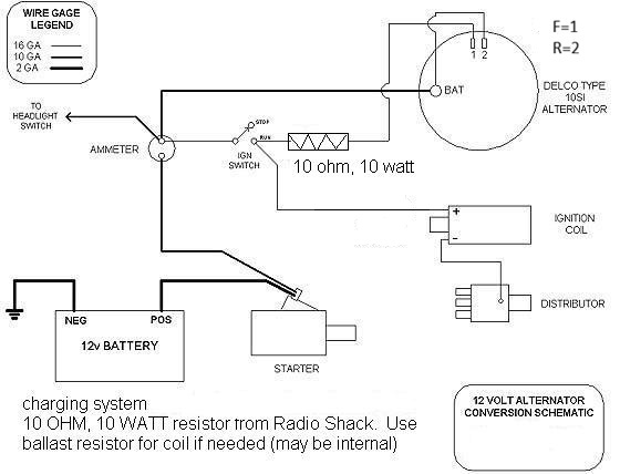 ------------- Like them all, but love the "B"s. |
Posted By: steve(ill)
Date Posted: 22 Jun 2026 at 1:48pm
the above is for a PUSH ROD starter... If you have a solenoid and key switch/ button... it looks more like this....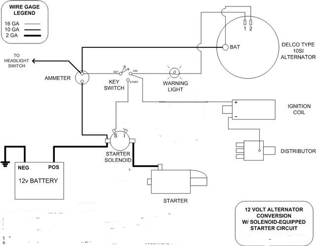 ------------- Like them all, but love the "B"s. |
Posted By: MB 121
Date Posted: 22 Jun 2026 at 7:19pm
|
Thanks for wiring schematic much appreciated mine would be pushrod key. |
Posted By: MB 121
Date Posted: 22 Jun 2026 at 7:24pm
| I will just run the sensing lead back to key switch it works the way it's wired now it has a magnetic pull the current way it's wired so from what I've read it's working. Correct |