Homemade Snap Coupler Implement
Printed From: Unofficial Allis
Category: Allis Chalmers
Forum Name: Farm Equipment
Forum Description: everything about Allis-Chalmers farm equipment
URL: https://www.allischalmers.com/forum/forum_posts.asp?TID=199024
Printed Date: 24 Jun 2024 at 7:00am
Software Version: Web Wiz Forums 11.10 - http://www.webwizforums.com
Topic: Homemade Snap Coupler Implement
Posted By: MadCow
Subject: Homemade Snap Coupler Implement
Date Posted: 02 Jan 2024 at 5:52pm
|
I would like to build some pallet jacks for the snap coupler. Has anybody built something that would work and have pointers? I have a 200 gallon water tank I want to build into a sprayer. It seems pretty straight forward to me, but ideas, suggestions and warnings would be appreciated!
|
Replies:
Posted By: DrAllis
Date Posted: 02 Jan 2024 at 6:02pm
| Lots been made with heavy 3" x 3" angle iron in an "A" frame tongue to the snap-coupler bell and twisted link chains done in a "V" to a cross bar to control sway. Attach your tool to the crossbar, which could be the same size angle iron on the pull tongue. |
Posted By: steve(ill)
Date Posted: 02 Jan 2024 at 6:42pm
|
the simple way would be to build something like this with lower arms 2-3 ft longer and set the tank on a couple welded on cross braces... Realize that as you raise the load, it will pivot on the bail and the back end raises faster than the front, so the load does not stay level.. Probably not a big deal on a water tank.... If you want to stay LEVEL like using forks, then you need the snap couple hitch like this, with a 3 point BOX or deck behind that with correct geometry to the top link.. 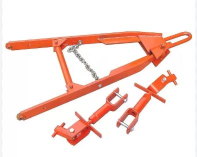 ------------- Like them all, but love the "B"s. |
Posted By: MadCow
Date Posted: 02 Jan 2024 at 7:40pm
|
Would it be easier/better to try and attach a spray boom to the cultivator bar? I can take the tines off so it's basically a tool bar. I could then lift the water with the loader. I'm just not sure my loader will lift 200 gallons of water, and I was hoping to take it off when I was done moving snow. |
Posted By: steve(ill)
Date Posted: 02 Jan 2024 at 8:02pm
|
you might be able to lift with the loader... but will you be able to steer ?? ------------- Like them all, but love the "B"s. |
Posted By: DMac
Date Posted: 02 Jan 2024 at 8:04pm
| i plan to build one myself. I have a 3point hitch 2 spear bale spike that I plan on starting with. I got an old wd drawbar with the ring that i plan on welding to the front and figure ill make a couple pieces to fit the snap latches and weld them in the correct location on the arch of the implement. |
Posted By: MadCow
Date Posted: 02 Jan 2024 at 9:22pm
I have power steering. But probably not gonna steer well enough to stay within rows. Good point.
The lifting connection arms are what I'm not totally clear on how I'm gonna do. I feel like there should be an easy way to repurpose top links. But nothing's coming to mind. |
") steve(ill) wrote:
steve(ill) wrote:Posted By: steve(ill)
Date Posted: 02 Jan 2024 at 9:46pm
|
are you trying to eliminate the snap latch and just run a adjustable bar from the lower arm to the lift arm ?? ------------- Like them all, but love the "B"s. |
Posted By: MadCow
Date Posted: 02 Jan 2024 at 10:35pm
|
Something like this is what I'm thinking. None of the dimensions
are figured, and the enigneering isn't done. I would the build a box to
sit the tank on between the 3" x 3" tubes. The lift arms aren't
adjustable, but not sure they would need to be.
 |
Posted By: MadCow
Date Posted: 02 Jan 2024 at 10:41pm
| With a slight modification, could put some hydraulic cylinder on it and the forks to make the forks levelable - wouldn't be self levelling like a 3 point. But if I really cared there would be options. |
Posted By: steve(ill)
Date Posted: 02 Jan 2024 at 10:41pm
|
that should work OK.... The vertical bars dont have to adjust... but they have to pivot at both ends.... just realize that the "LIFT" is going to pivot on the front Bail hitch... so the back end of the tank is going to swing thru an arc as it raises... Not a big problem.... thats basically how all implements on the snap coupler work. Nice drawing...... what program ? ..... part of your work/ job ?
------------- Like them all, but love the "B"s. |
Posted By: MadCow
Date Posted: 02 Jan 2024 at 11:39pm
I'll also probably add plates in an "X" shape between the vertical arms to stop it swinging left and right. My grader and cultivator do that. SOLIDWORKS. I'm an ME in education and detailing engineer by trade. Play farmer on the weekends. |
Posted By: Les Kerf
Date Posted: 03 Jan 2024 at 7:23am
I miss having Solidworks available to me now that I am retired, it sure is a sweet design program
|
Posted By: jaybmiller
Date Posted: 03 Jan 2024 at 7:58am
 ------------- 3 D-14s,A-C forklift, B-112 Kubota BX23S lil' TOOT( The Other Orange Tractor) Never burn your bridges, unless you can walk on water |
Posted By: jaybmiller
Date Posted: 03 Jan 2024 at 8:00am
|
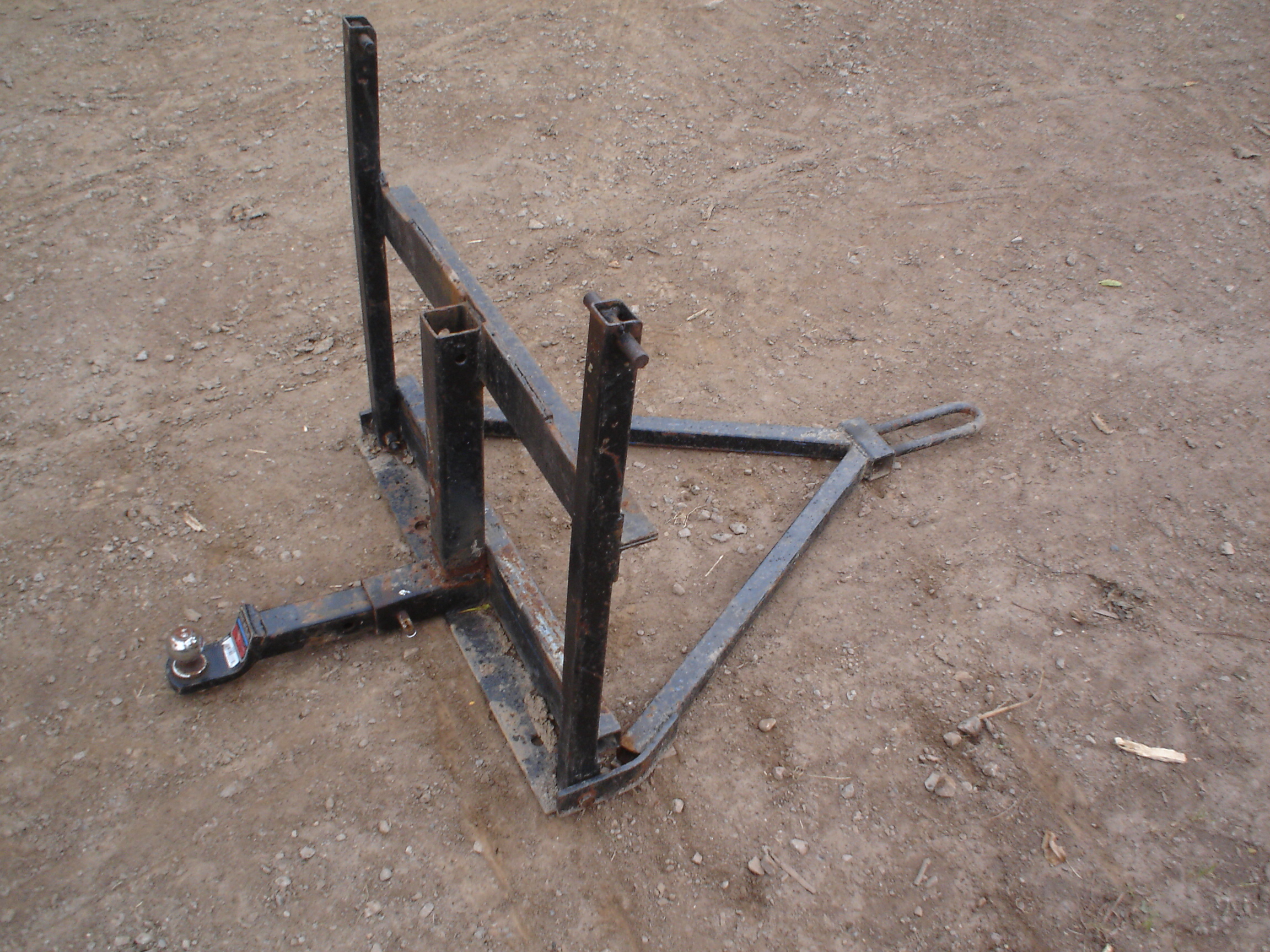
oopsy forgot to add.. made this 20 years ago, 42" forklift forks hang from it, will lift 2500# logs. OK, she ain't a purdy store bought gal, but has worked GREAT since day one !!! ------------- 3 D-14s,A-C forklift, B-112 Kubota BX23S lil' TOOT( The Other Orange Tractor) Never burn your bridges, unless you can walk on water |
Posted By: MadCow
Date Posted: 03 Jan 2024 at 8:12am
That looks great!, and simple! You must back up to it, clip the lift arms on, and then swing the drawbar hook in? Do you have any sketches or dimensions for it? I'll probably take my own, but a concensus would be great. Are those lift arms pinned to the bottom? Does that make the forks lift level?
|
Posted By: MadCow
Date Posted: 03 Jan 2024 at 8:15am
I always say I get to play on the computer all day. There's nothing quite as slick as solidworks. Fusion 360 is close - but it's not free anymore.
|
Posted By: steve(ill)
Date Posted: 03 Jan 2024 at 8:32am
Jay has a nice , simple hitch right there... The Pivot bolts at the boot would appear to be the weak link if any. A clevis or saddle that holds both sides of the arm would strengthen the frame.. Since the 2 x 2 hitch is connected to the lift arm instead of the lower arms it would tend to LIFT more horizontal... Dimension / placement of the vertical lift frame would determine how LEVEL it lifts. ------------- Like them all, but love the "B"s. |
Posted By: steve(ill)
Date Posted: 03 Jan 2024 at 8:41am
|
one thing you can do is make a little frame from plywood and 2x4 for a test.... make it so you can easily move the lower pin point forward and back. and change the HEIGHT of the frame up the to lift arms.... I did that with a set of forks to put on a "B" 3 point and figure the best Dimensions to get it to lift LEVEL.
you can also draw it out on a piece of graph paper showing the LOWER and RAISE positions of the lower arms and upper arms... then measure various places on the lower arm and the height of vertical bars to try to get somewhat LEVEL lift design... PRIOR to cutting out any parts. ------------- Like them all, but love the "B"s. |
Posted By: jaybmiller
Date Posted: 03 Jan 2024 at 8:46am
|
1/2" grade 8 bolts, lower arms are 1 1/2" square tubing, the "U" I bent by hand,lift latch pins are 5/8" bar so uprights are 1 1/2", 2" sleeve with 2" center 'post', 2" angle iron for cross pieces. built it after getting the forks for free( dumpster dive), replaced the FREEMAN loader, so no real plans.... made the 'arms' first,long, then cut to length after making the snap coupler section. ------------- 3 D-14s,A-C forklift, B-112 Kubota BX23S lil' TOOT( The Other Orange Tractor) Never burn your bridges, unless you can walk on water |
Posted By: MadCow
Date Posted: 03 Jan 2024 at 9:51am
You actually made me rethink my whole design. Probably do something closer to what you have. Then the frame that holds my water tank can have the same "hooks" that a pallet for has, and I can just back up and grab it.
|
Posted By: jaybmiller
Date Posted: 03 Jan 2024 at 10:01am
|
Mine has hauled 1,000s of skids as well as 20 IBC totes..here,there, everywhere... it even hauled tandem pull discs 2 miles to friends farm several times(stuck 'pole boom' into vertical tubing, several chains....kinda swayed a bit but everyone stayed away from me ! ------------- 3 D-14s,A-C forklift, B-112 Kubota BX23S lil' TOOT( The Other Orange Tractor) Never burn your bridges, unless you can walk on water |
Posted By: steve(ill)
Date Posted: 03 Jan 2024 at 12:33pm
|
MadCow .... if you make a drawing, post it so all can see. I would be interested in seeing your design. ------------- Like them all, but love the "B"s. |
Posted By: exSW
Date Posted: 03 Jan 2024 at 4:31pm
 I've got the real thing. AC SC pallet forks. They work pretty slick. If I can I'll find pics. I've got the real thing. AC SC pallet forks. They work pretty slick. If I can I'll find pics.
------------- Learning AC...slowly |
Posted By: MadCow
Date Posted: 04 Jan 2024 at 9:08am
 Rev 2 layout. I'm thinking the lower bar should be offset from the upper bar, so that when the lift is down with the forks on the fork tynes would be angled to parallel to the ground. The height of the top tyne carrier will need to be figured so that when the lift is all the way down, the tynes will be on the ground. Which may vary depending on the tynes used. I used round bar on the bottom, because I'm thinking with a little modification of the layout you could adapt a universal skid steer connector to fit on this, with a couple hydraulic cylinders to control the pitch.
|
Posted By: MadCow
Date Posted: 07 Mar 2024 at 1:41pm
|
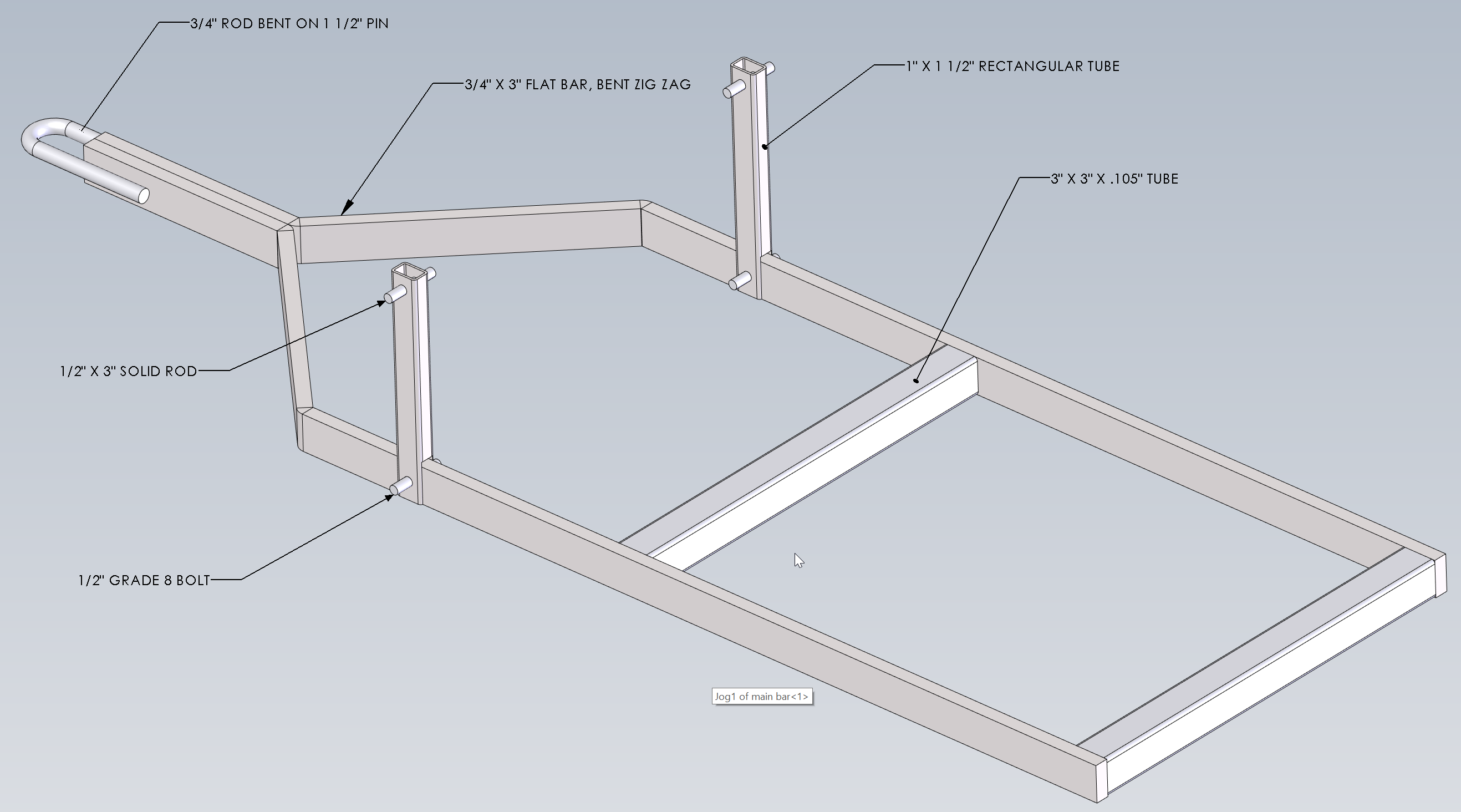
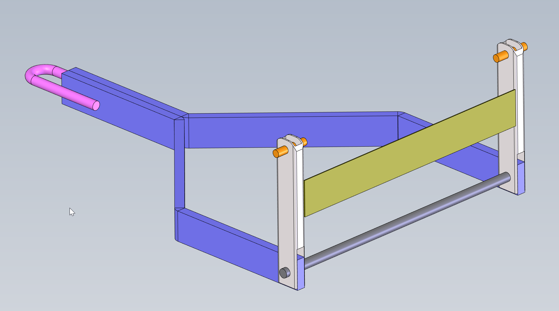
Got around to making a drawing. Anybody think this will work? The 1/4" holes in item 5 are for washers and pins to hold the lift arms in the right place - may or may not be needed. Very little welding, but I would probably need someone to do the bending - not sure how to get around that. It *should* be able to go from all the way down - to touching the ground so the lift arms can pick it right up from the ground - to all the way up. On a D15 at least. Struggled to get it to avoid the pumpkin - but I will hopefully be building this in the next month or so. With little modification to the 1" bar should be able to get a skid steer universal quick attach to work on it - maybe even with some hydraulics. 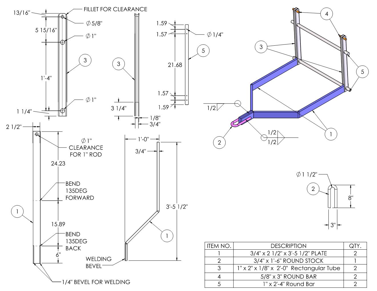 |
Posted By: steve(ill)
Date Posted: 07 Mar 2024 at 4:19pm
|
From a Welders point of view... I would not bend anything.. Cut and weld all the corners......... guess it depends on access to a bender, and you welding ability.. do the uprights #3 rotate with respect to the frame #1 ? .... what locks them together. ------------- Like them all, but love the "B"s. |
Posted By: DiyDave
Date Posted: 07 Mar 2024 at 4:39pm
Easiest way would be to find an old SC plow or bush hog and pull the tongue, eye and lift arms off of it. That way you only have to attach the rest of it to the pivot hole already in the SC frame. I do know that a SC bush hog frame is mighty close, width wise, to cat 1 3 point hitch... ------------- Source: Babylon Bee. Sponsored by BRAWNDO, its got what you need! |
Posted By: MadCow
Date Posted: 07 Mar 2024 at 5:03pm
Welding ability is yet to be determined - I figured it'd be easier to find someone that could bend them while I wait, for cheaper, than I could find someone to weld the quality needed at the angles. Where the flats meet together there's a lot of space and a lot of weld I'm not too worried about sucking.
Yes they rotate. They are "locked" together by the 1" rod (5) going through them. Putting pins and washers on the outside of #3 to hold it together. There may need to be pins on the inside to stop the beams (1) from pinching together - but I don't think I'll need them.
|
Posted By: MadCow
Date Posted: 07 Mar 2024 at 5:06pm
Implements in general around me are. About 4 times higher than elsewhere in the country - and AC stuff is almost non-existent. It's almost cheaper to ship LTL from 14hrs away than it is to try and buy old implements locally. I've seen people post single row model 70 JD planters on a cobbled 3pt hitch with obvious rattle can paint for $1,500 and the post isn't up for more than 72 hrs before it's sold.
|
Posted By: rasman57
Date Posted: 07 Mar 2024 at 6:33pm
|
I have made a couple different snap coupler pieces for my D-14's . A boom pole and a trailer hitch 2x2 inch receiver frame . I use the receiver to slide in a hitch obviously, but also to carry one of those 6 foot by 2 foot simple carryalls that my 25 gallon sprayer rides in. It also is handy for tools and saws etc. I did as others said and used the eye from AC SC stuff just because it was a no brainer for me. What I did recently is add a 3point conversion to my narrow front D-14 because it is so much easier to find inexpensive 3 point implements that I can use for my non farming needs in the woodlot and around the property. Finding a used brush hog mower in 3 point was SO much easier AND cheaper than a Snap Coupler set up as you indicated. I do enjoy building my own contraptions and they have worked well. I built my own front loader fork frame to replace my bucket when needed, and use a couple old lift truck forks on it. I drilled and bolted all the steel together and then took it to the weld shop to make it heavy duty with no worries. The one thing to be aware of with the snap coupler and even the 3 point conversion is the arc of travel and lift height for whatever you decide to do. It is different geometry than the loader obviously and you need to take into account in your design. A carryall , level in the middle of arc travel is considerably "angled" at all the way up and down. You sure seem like the design aspect is right in your wheelhouse so material and functionality will be your costs. Too fancy and you could have paid for a 3 point conversion AND carryall. I like fabricating too so it appeals to me to DIY sometimes.
|
Posted By: steve(ill)
Date Posted: 07 Mar 2024 at 9:04pm
|
Madcow... what i was worried about is the LEVEL of the forks during raise and lower.. Your vertical arms are attached at the top to the rock shaft upper arms... Similar to what rasman said... linkage needs to be specific length to make the forks LEVEL as you raise and lower... Length of rock shaft upper arms, to distance of vertical legs from the bail point, etc...... I made a 3 point lift with forks and made the parts out of plywood and 2 x 2... Screwed it together and used 1/4 inch bolts for pivot points ... checking how the FORKS were for "LEVEL" as it raised and lowered... Changed the lengths of upper arms, pivot point location, etc .. until i got the forks as LEVEL as possible between raise and lower. That was the SECOND attempt, after i initially made one without thinking and the forks were dipped 10 degrees down when on the ground and 20 degrees UP when you raised it ... not good. ------------- Like them all, but love the "B"s. |
Posted By: MadCow
Date Posted: 08 Mar 2024 at 11:09am
|
Yeah. I'm almost more interested in doing the fabrication myself than in saving money or having anything "factory" looking. Although I suspect this will be cheaper. I used SOLIDWORKS and chose the length of the trailing arms such that the #3 is perpendicular to the ground when the lifting arms are parallel to the ground. Since I don't have pallet forks yet to build around and the "drop" length on tines doesn't seem to be standard. Otherwise I would make it so the forks are perfectly level at 1" off the ground, to fit in a pallet. Some future options with this are, again adding hydraulics and a SSQA. Or you could add 1" holes to the trailing arm, allowing you to adjust the "level" height. Could also modify the trailing arms to have two pieces pinned together length wise at adjustable points. I like pins more than bolts because they can be just as strong, but they don't have nuts that rust on. Anything purely in shear can use shear pins. |
Posted By: rasman57
Date Posted: 08 Mar 2024 at 12:41pm
Yes they rotate. They are "locked" together by the 1" rod (5) going through them. Putting pins and washers on the outside of #3 to hold it together. There may need to be pins on the inside to stop the beams (1) from pinching together - but I don't think I'll need them. [/QUOTE]
I probably am not seeing this as described... but the geometry of the pivot point Steve asks about with respect to "locking" them together ... Doesn't that 90 degree angle need to be a solid fixed point if your forks attach to the lifting arms? If your horizontal frame from the bail carries your load, and your perpendicular lift arms raises the frame, your last drawing with a pivot point at the frame/lift arm point seems allow for the forks/load to need a top link ? Your initial concept drawing shows the load on the frame. The last, without forks or frame, seems to show the load being carried by the lift arms? Are the forks or plate being made "locked" by resting against that bottom round rod? I may be misunderstanding as my wife usually says.
|
Posted By: MadCow
Date Posted: 08 Mar 2024 at 3:47pm
|
The load (pallet forks, or in my case hooks attached to a water tote) hang off the 1" bars, either top or bottom. Which transfers to the uprights into the lift arms. The trailing arms stabilize it due to the cantilever on the center of mass. So the trailing arms and the lower 1" rod act as the "top link" just, on the buttom. If the uprights were solidly fixed to the trailing arms there would be weird forces in the joint, and in the upper snap buckles as well as the lower snap hook. I'll run some math and see if either method causes more torque in the lift arms, but at first blush I don't think there will be a difference. |
Posted By: DiyDave
Date Posted: 08 Mar 2024 at 6:19pm
|
The dragging/digging forks thing can be easily remedied, just get some forks offa an old backhoe FE loader, the ones that have an eye at the top, and a shaft through them, and a plate that hits the bottom, when you lift the forks up. BOLO for something that looks like this: https://www.diamondtoolstore.com/products/over-the-bucket-forks" rel="nofollow - https://www.diamondtoolstore.com/products/over-the-bucket-forks ------------- Source: Babylon Bee. Sponsored by BRAWNDO, its got what you need! |
Posted By: steve(ill)
Date Posted: 08 Mar 2024 at 6:42pm
|
I think your on the right track MC... The vertical links need to pivot at the bottom as you said..... again, it is the LENGTH of the upper arms compared to the vertical length PIVOT points at the bottom that will effect how much ANGLE the forks change as your raise them up... as you said, a hydraulic cylinder for PITCH could be installed, but getting the arm dimension and PIVOT POINT locations design can eliminate most of the need for that. ------------- Like them all, but love the "B"s. |
Posted By: steve(ill)
Date Posted: 08 Mar 2024 at 6:53pm
here is a simple drawing of a 3 point link. BLACK show the links in the lower position and RED uin the upper position.. "NORMALLY" as you raise an implement, the load angles UP SLIGHTLY.. Thats OK for a plow... but you probably want as little as possible on a set of FORKS.... You can draw it out on paper, or mock up with plywood links as a TEST to see what your going to have...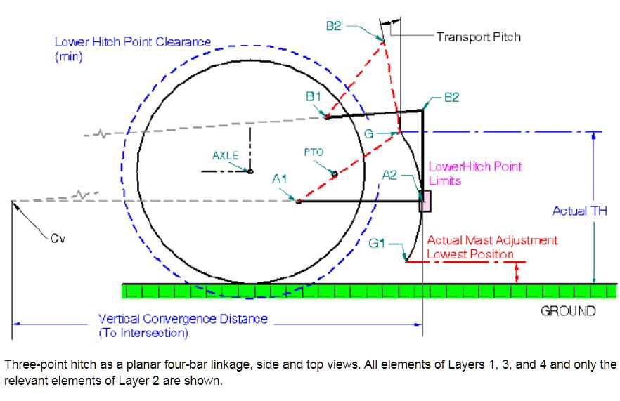 ------------- Like them all, but love the "B"s. |
Posted By: steve(ill)
Date Posted: 08 Mar 2024 at 7:23pm
Normally a design like a RHOMBUS, which makes the upper and lower arms the same length , and the vertical arm the same length as the distance between the upper and lower arms....... will result in a LIFT that does not change angles..... You may want SOME angle to tilt the load forward as you raise.. but maybe not as much as you get with a plow or blade.. ------------- Like them all, but love the "B"s. |