| Author |
 Topic Search Topic Search  Topic Options Topic Options
|
ac fleet 
Orange Level

Joined: 12 Jan 2014
Location: Arrowsmith, ILL
Points: 2226
|
 Post Options Post Options
") Thanks(0) Thanks(0)
 Quote Quote  Reply Reply
 Posted: 15 May 2024 at 1:08pm Posted: 15 May 2024 at 1:08pm |
|
hard to x'plain but depending on the position of the other switches,--it can do many different things. THAT is why mine are gone! lol! Got too confusing to mess with!
|
|
http://machinebuildersnetwork.com/
|
 |
|
Sponsored Links
|
|
|
jaybmiller
Orange Level Access
Joined: 12 Sep 2009
Location: Greensville,Ont
Points: 21669
|
Post Options
Thanks(0)
Quote Reply
Posted: 15 May 2024 at 2:16pm |
The seat switch will be in series and or parallel with other switches or relay contacts.
Again, a wiring diagram will show what's happening, a 'ladder' diagram even easier to see.
In my microcomputer projects I use a lot of on-open-off switches to get THREE unique 'conditions', and my remote energy systems use a 3 level communications bus that has baffled every hacker for 35 years.
To really blow your mind, coin tosses are NOT just heads or tails.
|
|
3 D-14s,A-C forklift, B-112
Kubota BX23S lil' TOOT( The Other Orange Tractor)
Never burn your bridges, unless you can walk on water
|
|
Les Kerf
Orange Level
Joined: 08 May 2020
Location: Idaho
Points: 666
|
Post Options
Thanks(0)
Quote Reply
Posted: 15 May 2024 at 3:09pm |
 jaybmiller wrote: jaybmiller wrote:
The seat switch will be in series and or parallel with other switches or relay contacts.
Again, a wiring diagram will show what's happening, a 'ladder' diagram even easier to see.
In my microcomputer projects I use a lot of on-open-off switches to get THREE unique 'conditions', and my remote energy systems use a 3 level communications bus that has baffled every hacker for 35 years.
To really blow your mind, coin tosses are NOT just heads or tails.
|
I have worked with relay logic, ladder logic, and digital (computer) logic; I need a proper schematic to trace it out though because every designer has a different way of thinking.
|
|
DaveKamp
Orange Level Access
Joined: 12 Apr 2010
Location: LeClaire, Ia
Points: 5651
|
Post Options
Thanks(0)
Quote Reply
Posted: 17 May 2024 at 12:14am |
Frequently, the safety circuits have 'fixed' elements (like the park brake switch, switches on the hand control levers, a switch contact through the PTO switch... and then they have a 'dynamic' element... the seat switch.
What does Dave mean by "Dynamic"???
Well, when you're sitting on the seat, bouncing across the yard, you're not actually holding that switch down ALWAYS... The switch is BoUnCinG!!!
So what the engineer typically does, is use the seat switch signal to control a relay that has a TIME DELAY function in it... so that, as long as the seat switch is closed for MOST of the time, the time-delay relay will maintain a closed contact (like the 'fixed' elements).
It is a 'de-bouncing' circuit. When those TD relays fail, they either DON'T work, or they DON'T time very well... they become intermittant... goofy... etc. Usually they're in a little 'black box' module, and the module controls a common automotive plug-in relay.
When the module goes bad, this kind of thing starts to happen.
But just to make it clear- ANY of the 'fixed' switch elements can cause erratic operation.... they're a 'safety loop', that when any of the 'safety conditions' are broken, it cuts the ignition. The fact that your brake is the OBSERVABLE 'cause' of the shutdown, simply means that all conditions are (by wiring) considered safe UNTIL you release the brake. On MY ZTR, if ANY of the hand controls are in the operating sector WHILE the brakes are applied, it kills the ignition. If I take weight off the seat with the operating handles in a DRIVE position AND brakes are released, after 3 seconds, the system will kill ignition.
Edited by DaveKamp - 17 May 2024 at 12:19am
|
|
Ten Amendments, Ten Commandments, and one Golden Rule solve most every problem. Citrus hand-cleaner with Pumice does the rest.
|
|
BuckSkin
Silver Level

Joined: 12 Sep 2019
Location: Poor Farm
Points: 326
|
Post Options
Thanks(0)
Quote Reply
Posted: 17 May 2024 at 12:56am |
jaybmiller wrote:
OK, what model is it ? I've got 100-130 CC manuals here on this PC.... ...remember CC is made by MTD
|
The mower I am/was working on is 2006-model Z Force 50 with 2-cylinder Kohler
After I zip-tied the Seat Switch into thinking a very heavy woman was always sitting in the seat, my problem was solved.
I honestly do not believe a brand-shiny-new Seat Switch assembly would have changed my situation at all; everything is there and everything looks good as new; and, everything works wonderfully when bench-testing.
|
|
BuckSkin
Silver Level
Joined: 12 Sep 2019
Location: Poor Farm
Points: 326
|
Post Options
Thanks(0)
Quote Reply
Posted: 17 May 2024 at 1:12am |
jaybmiller wrote:
using cheap switches and relays.
|
I have accessed every hidden wire and switch on this machine and have not found a single relay; just a bunch of Normally Open and Normally Closed push-button switches; most of them having several "poles" , turning one thing ON when another is turned OFF.
In my quest for ideas and answers, I watched a You-Tube video where this guy flies in on a mower and completely cuts away every wire on it; when he got done, he had a wheel-barrow full of wires.
He then re-wired the machine minus all the "safety" junk and didn't use but maybe three wires.
After watching his video, it was tempting for me to do likewise.
We were chopping silage on ground where angels fear to tread when the truck I was driving slid sideways away from the chopper and off over a steep hill and almost into an old abandoned rock quarry full of water.
To the rescue came Massey-Ferguson 2016 Tractor of the Year; big huge 4x4 cab tractor and brand-new.
The guy driving the tractor was no novice.
Once we were all chained up and he started pulling me away from the quarries edge, that big tractor decided to shut down and die and here we went again; truck and tractor both sliding sideways over the hill.
After a bit, he managed to satisfy all the safety requirements and get the tractor started and running again and got us both back on firmer footing.
When he clumb down out of the Tractor of the Year, his only comment was "these modern safety features are gonna get some of us killed"
|
|
SteveM C/IL
Orange Level Access
Joined: 12 Sep 2009
Location: Shelbyville IL
Points: 8061
|
Post Options
Thanks(0)
Quote Reply
Posted: 17 May 2024 at 6:05am |
jaybmiller wrote:
The seat switch will be in series and or parallel with other switches or relay contacts.
Again, a wiring diagram will show what's happening, a 'ladder' diagram even easier to see.
In my microcomputer projects I use a lot of on-open-off switches to get THREE unique 'conditions', and my remote energy systems use a 3 level communications bus that has baffled every hacker for 35 years.
To really blow your mind, coin tosses are NOT just heads or tails.
|
Help me out Jay on the coin toss....
Edited by SteveM C/IL - 17 May 2024 at 6:06am
|
|
jaybmiller
Orange Level Access
Joined: 12 Sep 2009
Location: Greensville,Ont
Points: 21669
|
Post Options
Thanks(0)
Quote Reply
Posted: 17 May 2024 at 6:13am |
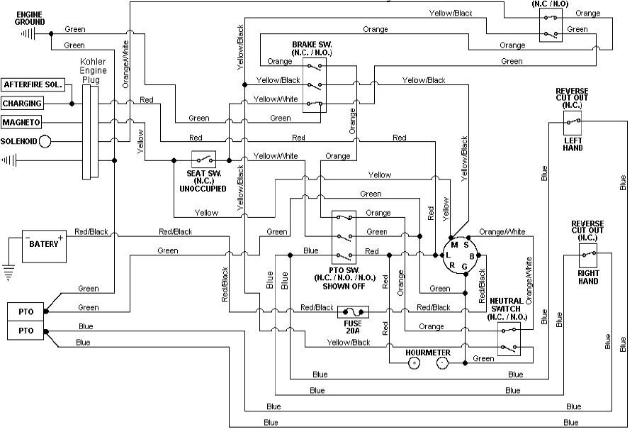
OK, took me 75 seconds to find to find the wiring....
..maybe someone can convert to an 'image' to repost it ?
Jay
|
|
3 D-14s,A-C forklift, B-112
Kubota BX23S lil' TOOT( The Other Orange Tractor)
Never burn your bridges, unless you can walk on water
|
|
jaybmiller
Orange Level Access
Joined: 12 Sep 2009
Location: Greensville,Ont
Points: 21669
|
Post Options
Thanks(0)
Quote Reply
Posted: 17 May 2024 at 6:23am |
|
|
|
3 D-14s,A-C forklift, B-112
Kubota BX23S lil' TOOT( The Other Orange Tractor)
Never burn your bridges, unless you can walk on water
|
|
jaybmiller
Orange Level Access
Joined: 12 Sep 2009
Location: Greensville,Ont
Points: 21669
|
Post Options
Thanks(0)
Quote Reply
Posted: 17 May 2024 at 6:26am |
OK, had to kill time while coffee was being made...... oopsy... upper right switch is the 'neutral switch'..... my cut and paste was a tad shaky ( only 1st cup of joe.....)
jay
|
|
3 D-14s,A-C forklift, B-112
Kubota BX23S lil' TOOT( The Other Orange Tractor)
Never burn your bridges, unless you can walk on water
|
|
Les Kerf
Orange Level
Joined: 08 May 2020
Location: Idaho
Points: 666
|
Post Options
Thanks(0)
Quote Reply
Posted: 17 May 2024 at 9:31am |
A rather poorly drawn schematic 
|
|
BuckSkin
Silver Level
Joined: 12 Sep 2019
Location: Poor Farm
Points: 326
|
Post Options
Thanks(0)
Quote Reply
Posted: 17 May 2024 at 11:33am |
jaybmiller wrote:
|
Thanks for posting the diagram; that appears to be the exact same one I have been looking at.
Ever since I started studying that diagram, I have been puzzled about those two Grounds at extreme right of the picture.
From the actual PTO Clutch, at bottom right, the Green wire is an unbroken path to Engine Ground.
Then, at just above right-center, is a black dot which I take to be a splice/junction, with another wire going through the Kohler Engine Plug to Ground again ----- why both ?
Also, looking at the engine plug, on the engine side is two connected wires, "Afterfire Sol." and "Charging"; they become a Red wire that takes an unbroken path to the "L" terminal of the Key Switch; does this "L" get connected to "B" when the Key is On/Run ?
I am assuming that Red wire is the "Alternator/Charging wire, right ?
Reason I ask about the connecting of the "L" and "B" is that another Red wire junctions with the main Red wire and is 12-volt power to the PTO-Clutch through the PTO Switch, where it splits into the two Blue wires that pass through the Reverse cut-out switches on their way to being power to the clutch itself.
By the way, the best thing I have done to this mower is disabling those Reverse Cutout Switches so that I can now mow when backing up; it makes all the difference in the world in tall/tough grass and whether it gets cut or not.
|
|
BuckSkin
Silver Level
Joined: 12 Sep 2019
Location: Poor Farm
Points: 326
|
Post Options
Thanks(0)
Quote Reply
Posted: 17 May 2024 at 11:45am |
Les Kerf wrote:
A rather poorly drawn schematic
|
and I can see no hint nor evidence of the two tiny "secret" switches hidden within the mower side of the Seat Switch plug/connector.
Things are working for me now and I have more pressing matters to attend to; however, if I have to dive into this again, or I get so curious about it that I can't stand it, I intend to cut that plug out of the circuit and thoroughly bench test it to determine just what and when those two tiny switches are doing.
I am convinced that, if that plug were a normal two-wire plug, then it would not/could not ignore any and all attempts at jumper-wiring it.
I bet the "Real" reason for those two secret switches is to force sales of un-needed Seat Switches; people scratch their heads and puzzle while the grass gets taller and the rain keeps coming and they give up and order a new Seat Switch that does nothing to fix their problem but they keep it anyway.
|
|
Les Kerf
Orange Level
Joined: 08 May 2020
Location: Idaho
Points: 666
|
Post Options
Thanks(0)
Quote Reply
Posted: 17 May 2024 at 1:28pm |
BuckSkin wrote:
...I bet the "Real" reason for those two secret switches is to force sales of un-needed Seat Switches; people scratch their heads and puzzle while the grass gets taller and the rain keeps coming and they give up and order a new Seat Switch that does nothing to fix their problem but they keep it anyway. |
That is known as "The Brother-in-law Effect"; the guy that designed it has a brother-in-law who sells the little switches  |
|
Les Kerf
Orange Level
Joined: 08 May 2020
Location: Idaho
Points: 666
|
Post Options
Thanks(0)
Quote Reply
Posted: 17 May 2024 at 2:57pm |
BuckSkin wrote:
...does this "L" get connected to "B" when the Key is On/Run ? |
Probably. A proper schematic will show the internal contacts of the ignition switch; it would also actually label the switch so that we would not need to guess. This is really just a wiring diagram rather than a schematic.
BuckSkin wrote:
I am assuming that Red wire is the "Alternator/Charging wire, right ? |
Again, probably. I am assuming so as well.
BuckSkin wrote:
Reason I ask about the connecting of the "L" and "B" is that another Red wire junctions with the main Red wire and is 12-volt power to the PTO-Clutch through the PTO Switch, where it splits into the two Blue wires that pass through the Reverse cut-out switches on their way to being power to the clutch itself. |
Yup, that looks pretty straightforward to me too; the 'ignition' switch needs to be able to disconnect the "L" and "B" terminals so as to not discharge the battery when the engine isn't running but needs to connect them to start the engine and charge the battery.
Since it has a magneto ignition, the 'Ignition' switch doesn't need to supply power to a coil. Most of the circuitry is dedicated to killing the magneto. It is interesting that it shows two Neutral switches, are there really two of them?
|
|
jaybmiller
Orange Level Access
Joined: 12 Sep 2009
Location: Greensville,Ont
Points: 21669
|
Post Options
Thanks(0)
Quote Reply
Posted: 17 May 2024 at 3:17pm |
re: looking at the engine plug, on the engine side is two connected
wires, "Afterfire Sol." and "Charging"; they become a Red wire that
takes an unbroken path to the "L" terminal of the Key Switch; does this
"L" get connected to "B" when the Key is On/Run ? Kohler is clever, the 'charging' module is tied to the 'afterfire solenoid' ON the engine. If you spun the engine,say with recoil starter', engine runs without need of a battery. You need to understand that if a manufacturer can make a 'generic' device (engine in this case )it can be easily used in several devices NOT specific to just one mower seriers of one brand.
As for the grounds, often it's how the wiring harness is made and installed.
Yes, RED, is the alternator/rectifier/regulator output. it goes to 'L' and powers everything. When key is on, it's also on 'B',goes through 20A fuse to recharge the battery. You can pull the 20A fuse and the unit will still run.
Internal connections of the ignition switch are usually shown in a chart and while most Indak switches look the same, Internally they can be quite different so you MUST eplace with one specific to your machine.
The seat switch is just 2 wire, simple SPST switch, NO 'magic' that I can see.
Edited by jaybmiller - 17 May 2024 at 3:20pm
|
|
3 D-14s,A-C forklift, B-112
Kubota BX23S lil' TOOT( The Other Orange Tractor)
Never burn your bridges, unless you can walk on water
|
|
BuckSkin
Silver Level
Joined: 12 Sep 2019
Location: Poor Farm
Points: 326
|
Post Options
Thanks(0)
Quote Reply
Posted: 17 May 2024 at 5:31pm |
Les Kerf wrote:
It is interesting that it shows two Neutral switches, are there really two of them?
|
Yes; two Neutral Switches, one each side where the "arms" rest when not in action.
On this machine, if either arm is not against it's Neutral Switch, in the "at rest" position, it will not start; but then, once started, they can be anywhere and it will run; however, once it is running and the Park Brake is engaged, if you move either arm from it's at rest position, against the Neutral Switch, the engine will die; you must first dis-engage the Park Brake and then move the arms.
I guess that is to keep you from running around with the brake engaged.
It looks to me like it would be less wear and tear on the engine and starter/flywheel if, instead of any wrong move killing the engine, a cattle prod were incorporated within the seat and the operator get a bit of wake-me-up juice whenever a wrong maneuver were attempted; the lesson would be long remembered and the operator would be sure to follow proper procedure in the future.
|
|
DiyDave
Orange Level Access

Joined: 11 Sep 2009
Location: Gambrills, MD
Points: 50749
|
Post Options
Thanks(0)
Quote Reply
Posted: 17 May 2024 at 7:02pm |
BuckSkin wrote:
Les Kerf wrote:
It is interesting that it shows two Neutral switches, are there really two of them?
|
Yes; two Neutral Switches, one each side where the "arms" rest when not in action.
On this machine, if either arm is not against it's Neutral Switch, in the "at rest" position, it will not start; but then, once started, they can be anywhere and it will run; however, once it is running and the Park Brake is engaged, if you move either arm from it's at rest position, against the Neutral Switch, the engine will die; you must first dis-engage the Park Brake and then move the arms.
I guess that is to keep you from running around with the brake engaged.
It looks to me like it would be less wear and tear on the engine and starter/flywheel if, instead of any wrong move killing the engine, a cattle prod were incorporated within the seat and the operator get a bit of wake-me-up juice whenever a wrong maneuver were attempted; the lesson would be long remembered and the operator would be sure to follow proper procedure in the future. |
That would make a good video... 
|
|
Source: Babylon Bee. Sponsored by BRAWNDO, its got what you need!
|
|


