| Author |
 Topic Search Topic Search  Topic Options Topic Options
|
dfwallis 
Orange Level

Joined: 09 Mar 2023
Location: DFW
Points: 523
|
 Post Options Post Options
") Thanks(0) Thanks(0)
 Quote Quote  Reply Reply
 Posted: 05 Aug 2024 at 6:05pm Posted: 05 Aug 2024 at 6:05pm |
Tachometer project status update 8/5/2024:
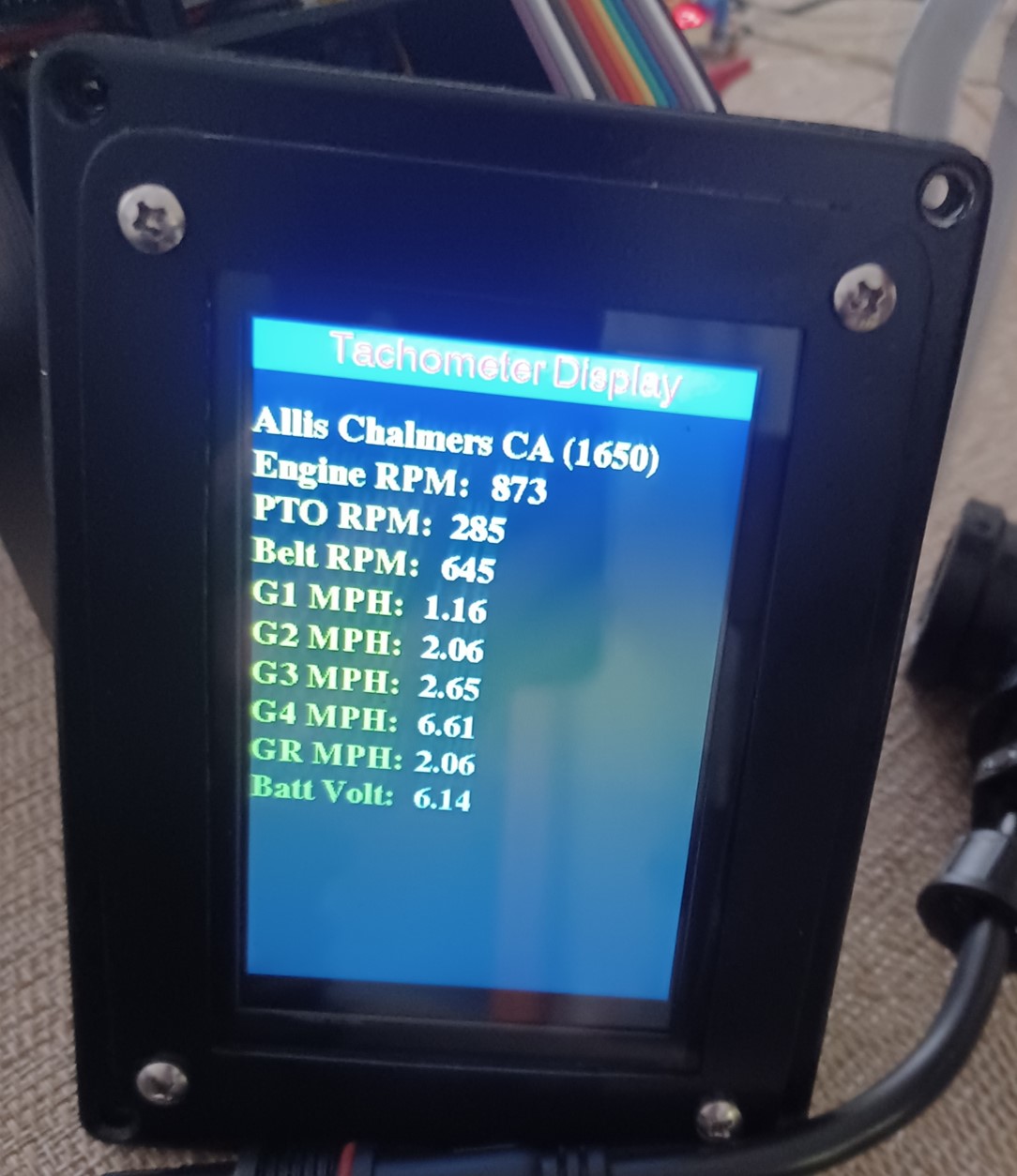
First power-up of the PCB was successful (nothing blew up). I do have a few issues to address. 1) The bezel is covering part of the display (thought I was careful, but apparently not careful enough). 2) The scaling for the battery voltage sensor is off. I had set it for a particular prototype resistor value and that resistor disappeared into a black hole. New resistor is a slightly different value (they have a fairly wide tolerance) plus I added a new zener clamp circuit to prevent the input from going over 3.3V (which should give a measurement range up to 16.5V power input)...slow progress in between yard work, pool work, etc.
|
|
1952 CA13092
|
 |
|
Sponsored Links
|
|
|
dfwallis
Orange Level
Joined: 09 Mar 2023
Location: DFW
Points: 523
|
Post Options
Thanks(0)
Quote Reply
Posted: 08 Aug 2024 at 4:41pm |
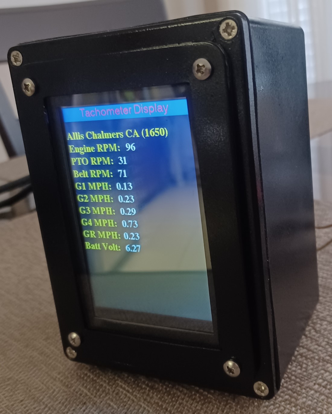
Tachometer project status update 8/8/2024:
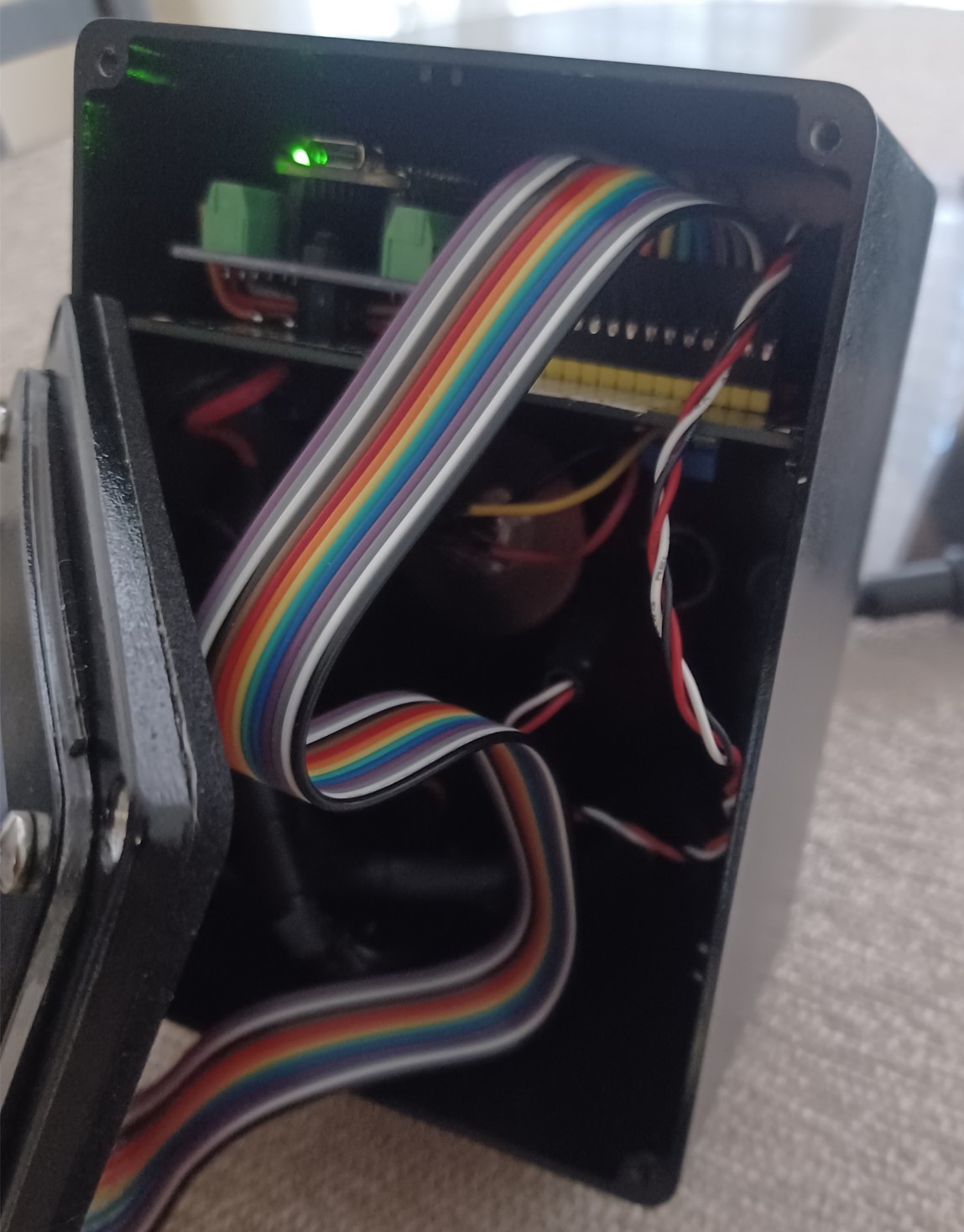
This is the "final" tach version (depending on how well it works installed). I still need to make the "power" harness (both harnesses will be cut to length on site). For this to work properly, the flywheel outer edge must be coated flat black and a single IR reflective strip will be applied. The reflective surface must be completely smooth to prevent spurious impulses. Depending on whether I can mount it close enough (< 2 inches) a plain white strip of tape or mylar will work. In testing, silver mylar worked slightly better, giving increased range and a stronger more consistent return. The width of the marker is to be determined. I'll start with 1 inch to provide a reasonable duration and reduce likelihood of missed pulses.
I also added a nice foam rubber gasket to the faceplate bezel and cleaned up the surround that was blocking some of the display pixels.
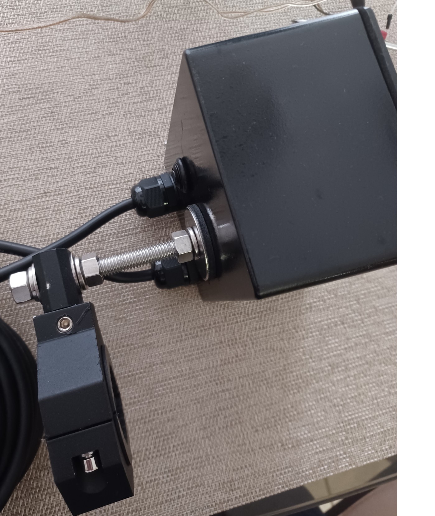
A view inside:
Reading the sensor through a 25 foot cable. Seems reasonably noise immune. Battery voltage is a tiny bit flaky. I tried to suppress noise but I should have probably tried a different noise suppression circuit design.
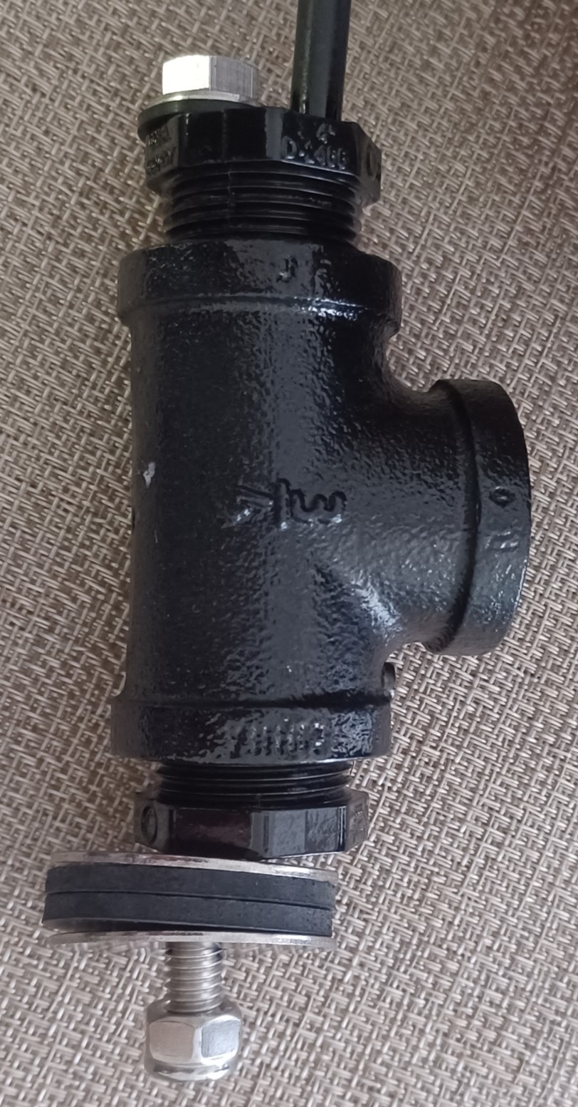
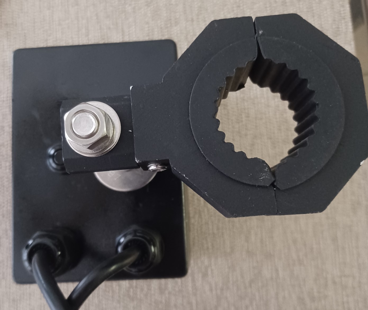
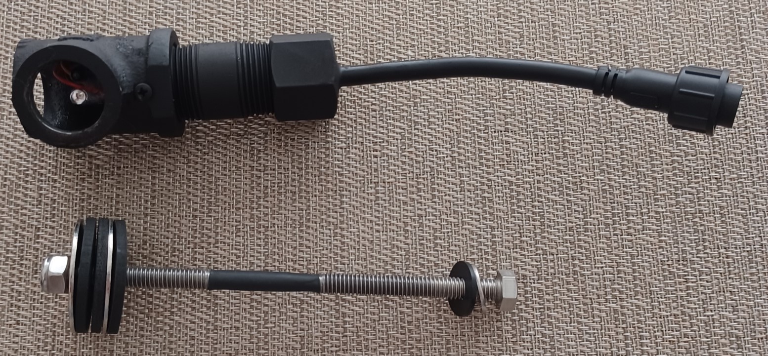
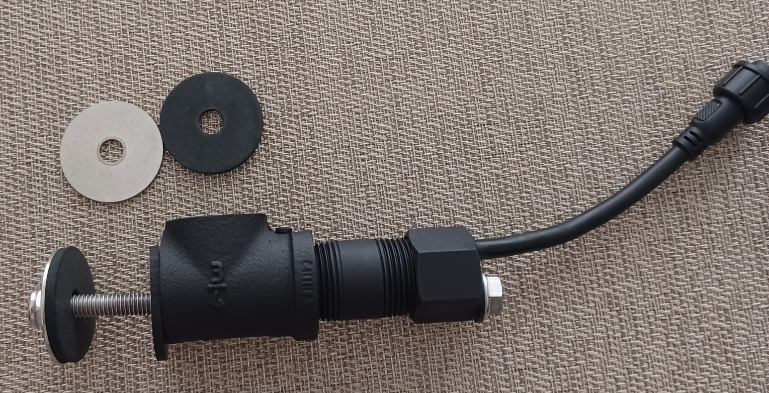
A side view of the sensor that will mount to the bottom of the bell housing through the loop in front of it (may need modifications on site).
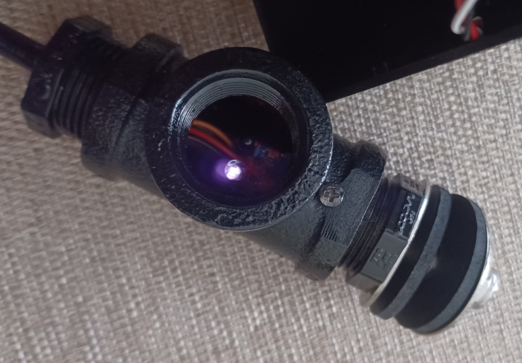
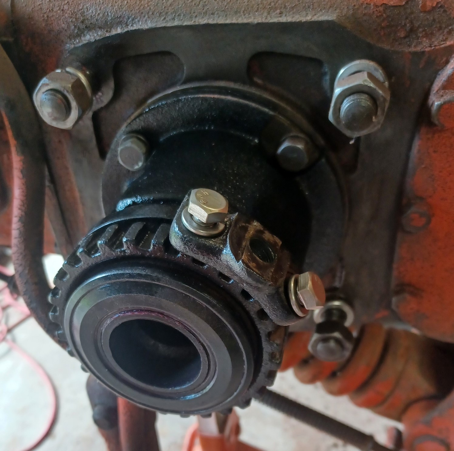
A view of the mounted IR sensor inside the fitting.
A profile view.
A back view of the mount (repeat).
A view looking down at the back.
|
|
1952 CA13092
|
|
dfwallis
Orange Level
Joined: 09 Mar 2023
Location: DFW
Points: 523
|
Post Options
Thanks(0)
Quote Reply
Posted: 18 Aug 2024 at 10:41am |
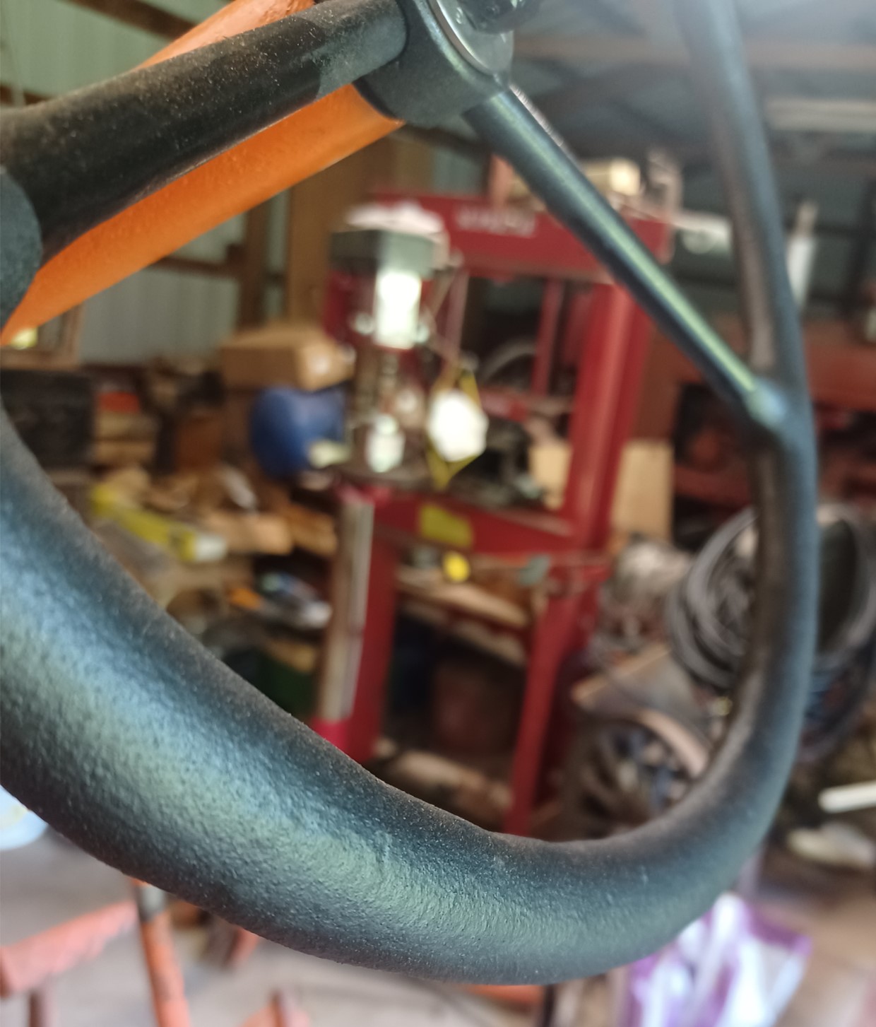
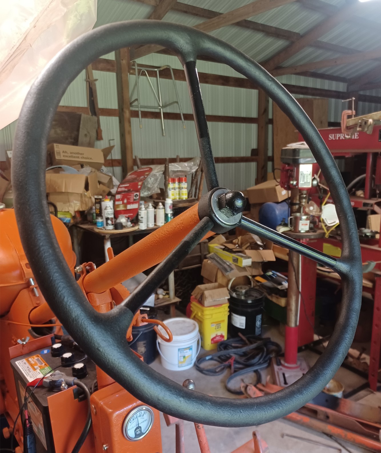
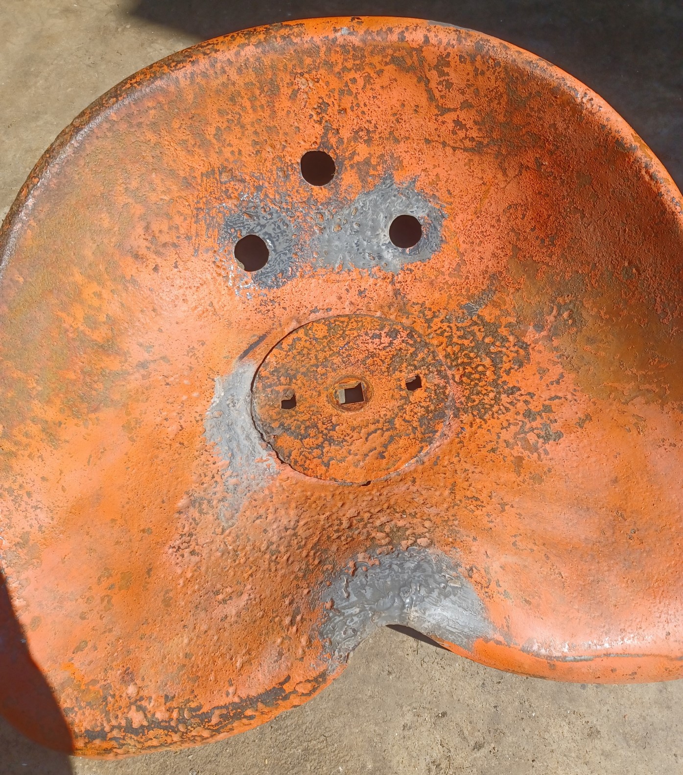
Here is a closeup view of the bed liner coating on the steering wheel.
Here is a full view. This coating is much tougher than the paint. I had used a very tough/hard paint, but I was worried it wouldn't hold up well. I think this will hold very well and has a good feel to it.
|
|
1952 CA13092
|
|
dfwallis
Orange Level
Joined: 09 Mar 2023
Location: DFW
Points: 523
|
Post Options
Thanks(0)
Quote Reply
Posted: 18 Aug 2024 at 11:03am |
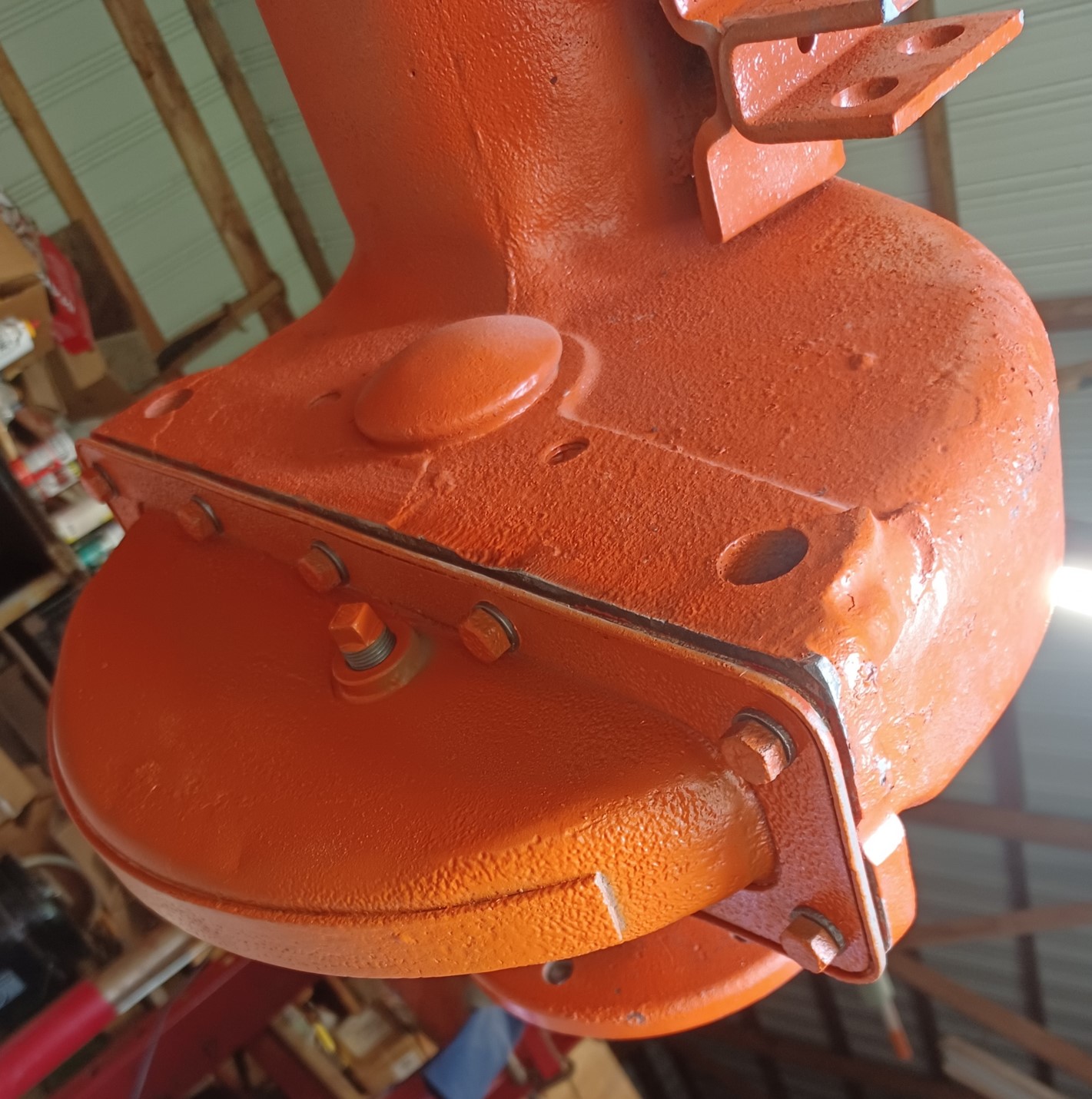
The hand clutch release mechanism cleaned up and painted. The bearing and the throwout adjustment were both completely locked up. I had to use a large pipe wrench to loosen them up. The bearing was cleaned and greased and seems to function perfectly, although it does tend to settle outward a bit when not under load. In order to set the clearance, I had to use a screwdriver to force it together to get the gap tool inserted. I made two new lock screws (ground the tips to fit in the adjustment wheel grooves) and adjusted to just the right length to be able to lock them down.
I was running out of time last trip so I decided to take the axle to the local (former) AGCO dealer for hand clutch repair. I was a little concerned because he did the repair (including religning and new springs/ball bearings) without removing the brake drum section from the axle. I bet that was difficult. In any case, there was little chance of actually testing/gauging the correct tolerances that way. After I got it back, I wanted to test it before I put everything back together. I had to put just enough structure together to operate the tractor (i.e. rails, brakes, seat). Initially it did not seem to be releasing. One thing that was concerning is that on at least 2 occasions, in attempting to release the clutch, a large cracking noise was heard, like a spring/ball seat popping into (or out of) place. This happened two times. After a final clearance adjustment, then the clutch started operating "correctly". It still has a slightly "off" feel to it, but my memories of using it are 50 years old. It does seem to be working correctly though as far as I can tell.
Installed the welded and POR15 sealed final drive oil pan. Added .75qt 80W90 gear oil...no leaks (yay). I will give the other (left side) one the same treatment later (not leaking but I bet it has some water in it like this one did). The rust pattern was weird...just needle sized pin holes with no rust surrounding the pin holes. How is that possible??
Edited by dfwallis - 18 Aug 2024 at 11:44am
|
|
1952 CA13092
|
|
dfwallis
Orange Level
Joined: 09 Mar 2023
Location: DFW
Points: 523
|
Post Options
Thanks(0)
Quote Reply
Posted: 18 Aug 2024 at 11:24am |
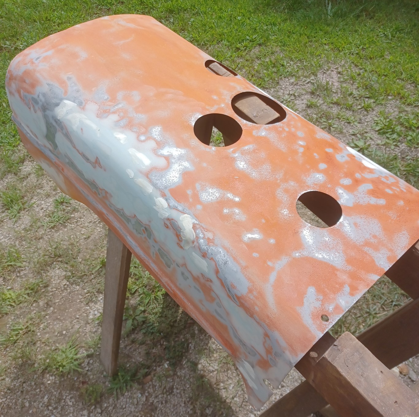
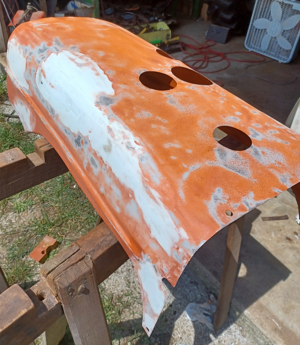
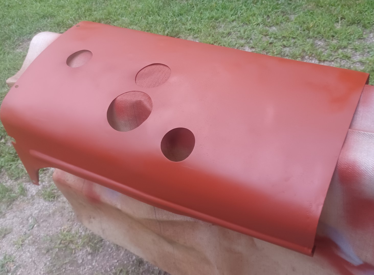
I spent days reworking the hood. It was severely damaged in a logging accident plus several hail events. I spent quite a lot of effort my prior trip but just wasn't getting the results I wanted, especially on the sides where the decals go. That was going to look awful. So I bought some body work tools and began pounding the heck out of it. Then I started bondo-ing the worst areas. I would have had to skim the entire surface to get it right. What a mess (not to mention the numerous rips and tears I welded). A sane person would have probably got new tin.
More bondo. Not clearly visible are the severe rust pits all over. Like the seat, some of the rust pits LOOK like they're deeper than the metal is thick :(
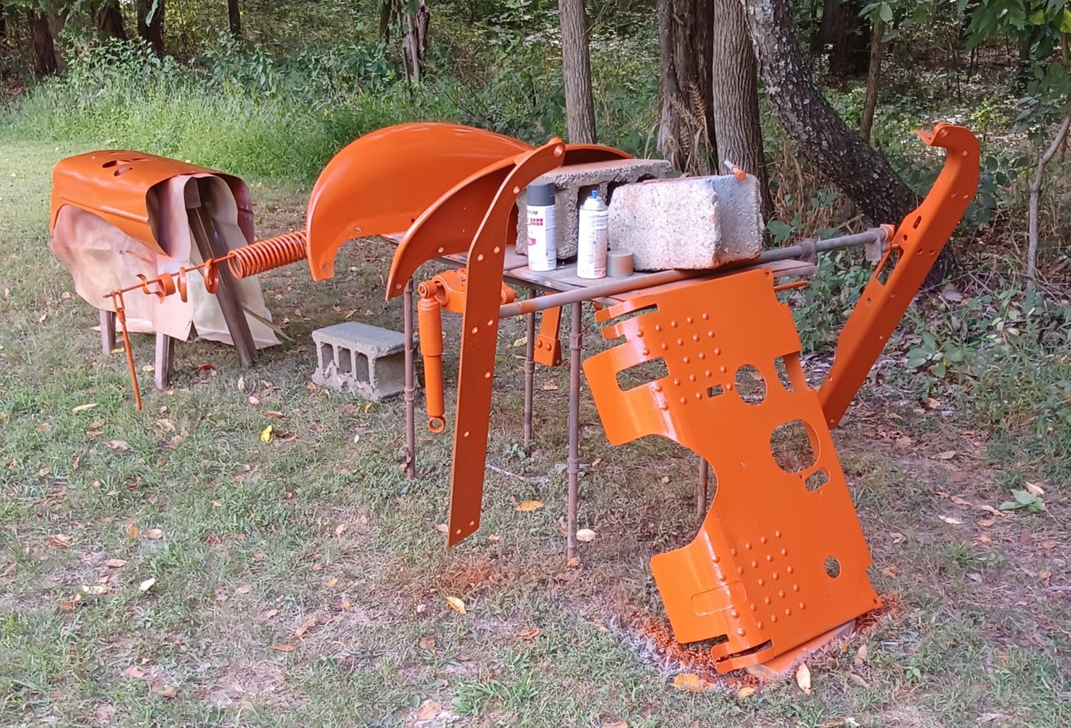
After 5000 coats of primer and days of sanding, I'd had enough (red deep fill primer). Good as it's gonna get.
Not really clear but the paint looks MUCH better this time. I had several issues previously:
1) Compressor was spitting out huge amount of water. To resolve, I purchased a 4 stage air dryer (which makes 5 stages given the one at the compressor). This made a massive difference for both painting and sand blasting. After i got the sand blaster cleaned out of all the hard chunks/flakes of sand, it was greatly improved in performance.
2) Massive bugs and tree residue (in May), plus a lot of rain adding to the compressor moisture issues.
3) I was following the directions on the Tallman's paint can previously. This time, I used the advice of "random internet guy" and mixed hardener and naphtha thinner in a 4-1-1 ratio. This massively improved the paint drying time, hardness, and gloss.
Edited by dfwallis - 18 Aug 2024 at 6:51pm
|
|
1952 CA13092
|
|
dfwallis
Orange Level
Joined: 09 Mar 2023
Location: DFW
Points: 523
|
Post Options
Thanks(0)
Quote Reply
Posted: 18 Aug 2024 at 11:38am |
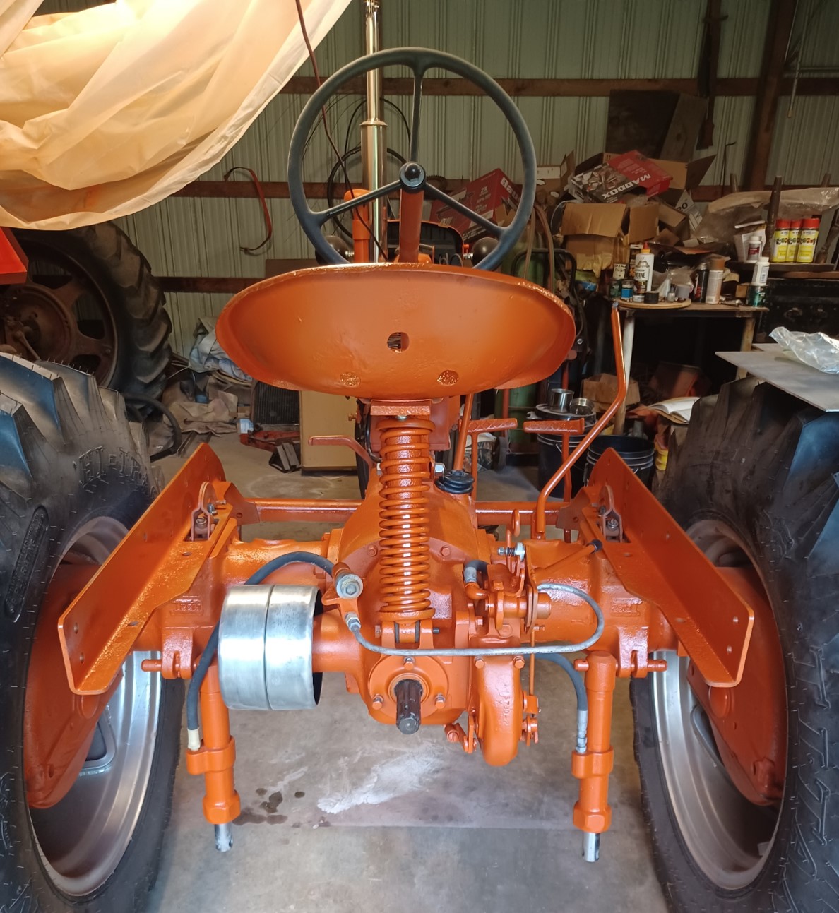
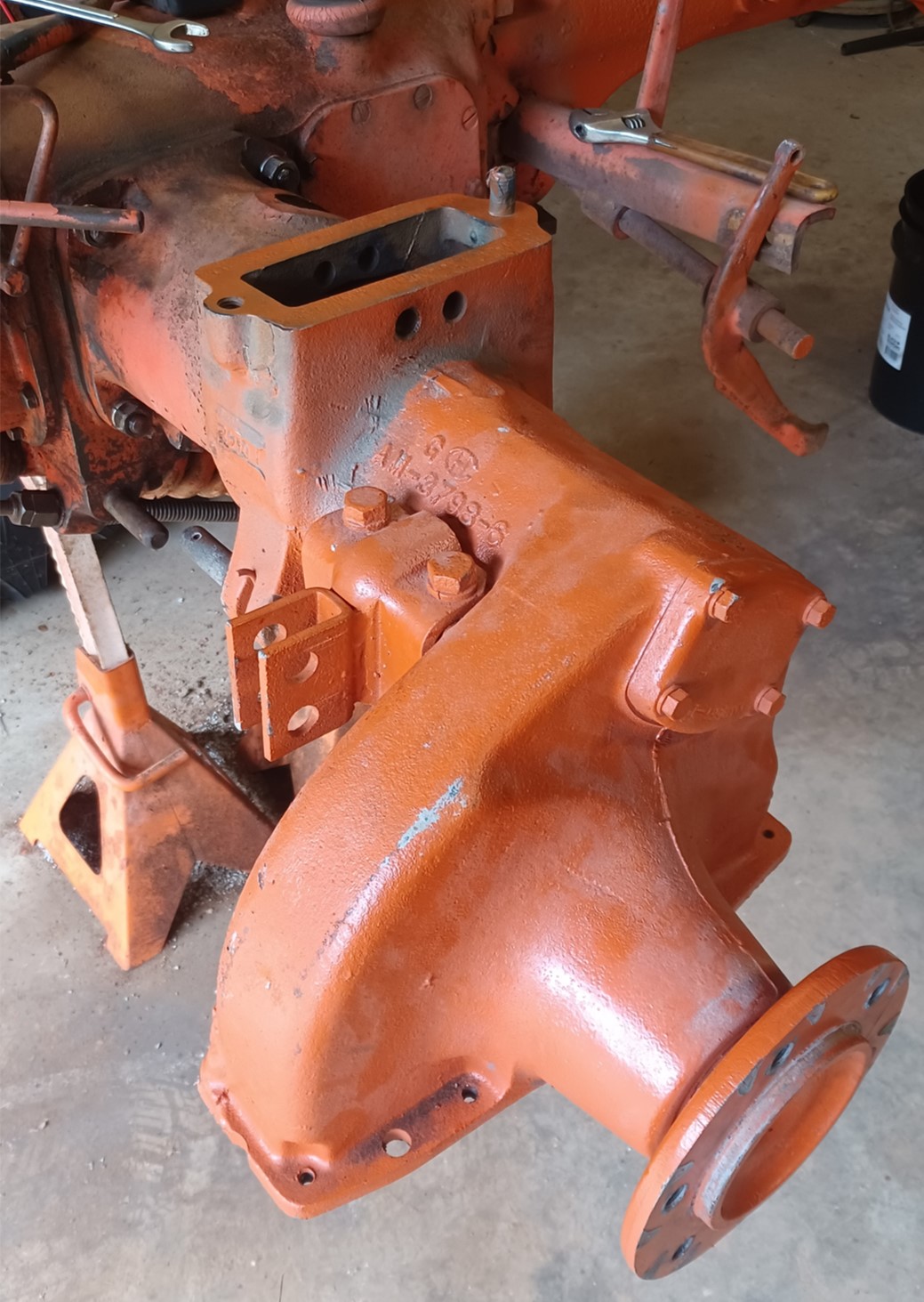
A view of the rear end sand blasted and painted. It has 3 coats of primer and 3 coats of color. I bought a nice black seat cushion to cover up the crusty seat :) If I had had another few hours this trip I might have installed the rest, but paint recommends waiting 7-10 days to let the paint cure. Here I just installed what was necessary to test the hand clutch. I also drained and put new gear oil in the tranny. Overall, given that the hand clutch SEEMs to be working, I'm happy with my progress this trip. A lot of progress in 6 days. Even spent some time with my brother trying to get the M running :) One problem I still have is that the governor seems to only bring the speed up to 1/4 throttle. The throttle rod was "straightened" to just one bend just behind the starter and now gets me full range of the control mechanism minus 1 notch (was 4 notches short before...it starts bending the rod at the last notch now). I can probably work the bending of the rod a little more and get the full range of the control correct.
I'm guessing that the governor spring is weak, but it doesn't look to be stretched.
The hydraulic hoses are split and frayed, I guess I'll try to replace those (hopefully I can find some swivel fittings that don't leak, I don't like the way they have to be twisted as-is).
I also cleaned up and removed some large dents in the belt pulley last fall and just installed it.
Edit: An interesting note is that both of the hydraulic cylinders were originally rusted solid in place (in the drawbar pin position). I could actually stand on them and jump up and down and they absolutely would not budge up or down. It took weeks of soaking and prying to get them loose.
Edit: I've decided that I have the throttle "surge" spring installed incorrectly and that is the likely cause of the throttle control issues.
Edited by dfwallis - 21 Aug 2024 at 8:11pm
|
|
1952 CA13092
|
|
dfwallis
Orange Level
Joined: 09 Mar 2023
Location: DFW
Points: 523
|
Post Options
Thanks(0)
Quote Reply
Posted: 18 Aug 2024 at 11:43am |
Tachometer project status update 8/18/2024:
As expected, I need to make two tiny mods.
1) The sensor housing itself (plumbing T) was cut to the correct dimensions. But this will require me to mount the sensor on the opposite (rear) side and change the entry point of the cable (no big deal).
2) The display housing needs about 1 inch more clearance to deconflict with the throttle and starter control rods (expected). (also need thinner rubber clamp mounts since the steering column diameter is larger than I remembered).
|
|
1952 CA13092
|
|
dfwallis
Orange Level
Joined: 09 Mar 2023
Location: DFW
Points: 523
|
Post Options
Thanks(0)
Quote Reply
Posted: 18 Aug 2024 at 2:09pm |
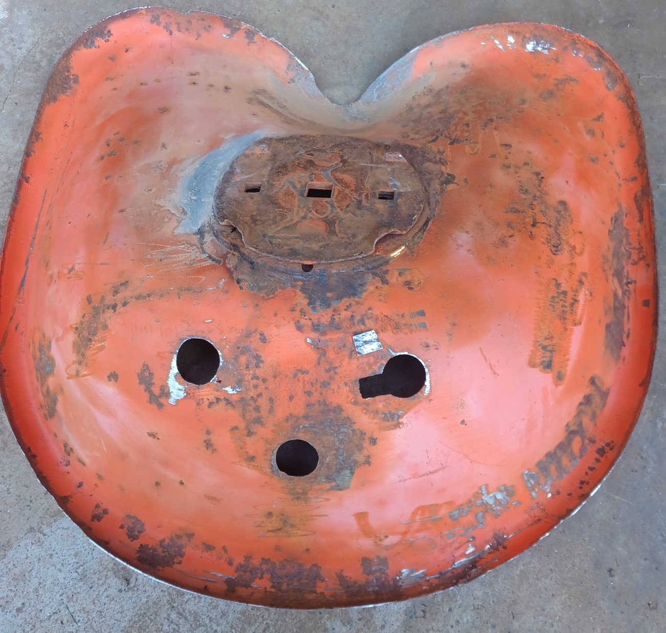
Showing where the seat was rusted through and welded and epoxy skim coated. I originally didn't plan on fixing the hole, but decided to go ahead. It came out nice and round-ish. It was sand blasted further before painting but I didn't get a good post paint pic (but you can probably imagine painted rust pits well enough).
Those are some DEEP rust pits.
|
|
1952 CA13092
|
|
CA13414
Silver Level

Joined: 25 Feb 2024
Location: Nebraska
Points: 255
|
Post Options
Thanks(1)
Quote Reply
Posted: 18 Aug 2024 at 8:55pm |
|
Your painting looks awesome. You are definitely more OCD than me in that regard. I was like.... one coat of primer is enought.... lets paint!!
Your work is looking awesome!
|
|
Helping the aged survive and thrive! 1953 CA
|
|
dfwallis
Orange Level
Joined: 09 Mar 2023
Location: DFW
Points: 523
|
Post Options
Thanks(0)
Quote Reply
Posted: 22 Aug 2024 at 10:50am |
Tachometer project status update 8/22/2024:
Installation clearance modifications:
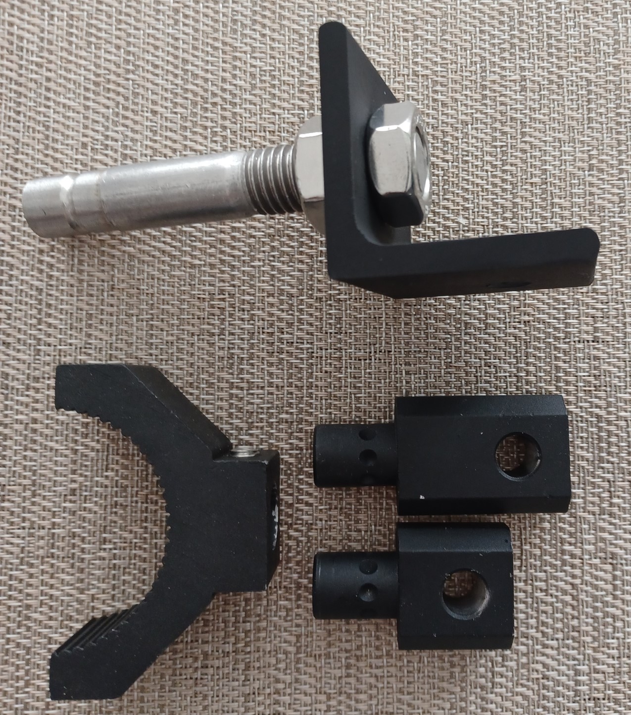
The tube clamp actually came with a slightly longer extension that I didn't remember. If that one isn't long enough, I've made one that gives me much more flexibility. I added a continuous groove for the pointed set screws to sit in to reduce the chance of accidentally pulling out. There will be lock washers in addition to the jam nuts.
The original clamp extensions only came with fixed set-screw positions. If needed, I can similarly groove it given that it's unlikely that the fixed positions will give the correct angle for the display.
The sensor itself had to be cut to fit the opening at the bottom of the bell housing and the mounting ring just in front. This required me to add an extension on the back side in order to provide enough clearance for the wiring harness. The pipe nipple was grooved on the end to allow the PCB screw to mount correctly. The nipple also decreased the clearance between the through bolt and the PCB so I ground a clearance in the middle of the through-bolt and covered it in shrink wrap tubing. There should be enough clearance, this was just a precaution.
There will be a shortened nipple protruding upward into the bell housing hole to prevent rotation. The exact rubber sealing arrangement is tbd. I intended to use gloss paint, but my last can of gloss black stopped spraying properly before it ran out of paint (broken button receptacle in the can)...:(
|
|
1952 CA13092
|
|