| Author |
 Topic Search Topic Search  Topic Options Topic Options
|
dfwallis 
Orange Level

Joined: 09 Mar 2023
Location: DFW
Points: 609
|
 Post Options Post Options
") Thanks(0) Thanks(0)
 Quote Quote  Reply Reply
 Posted: 05 Aug 2024 at 6:05pm Posted: 05 Aug 2024 at 6:05pm |
Tachometer project status update 8/5/2024:
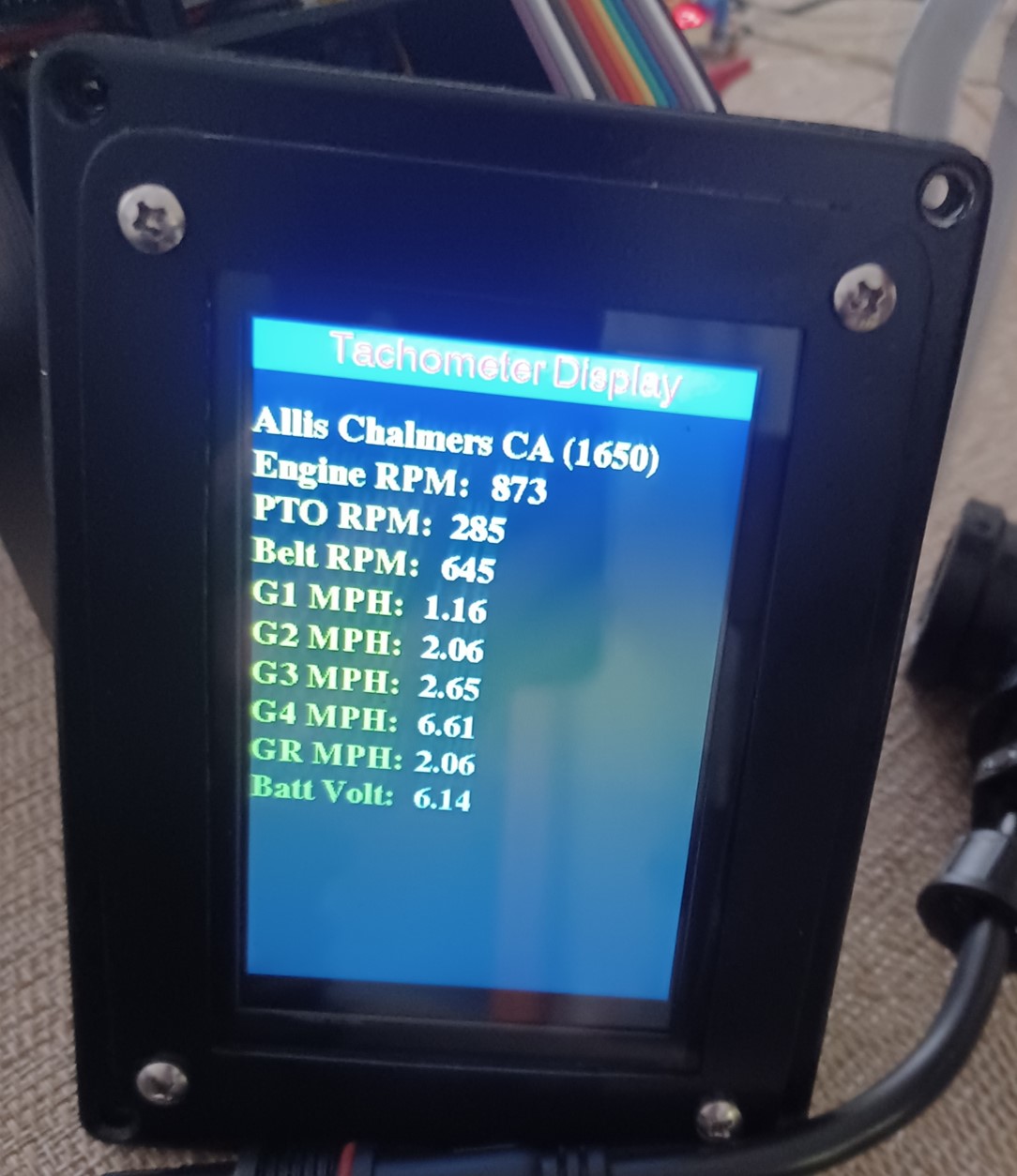
First power-up of the PCB was successful (nothing blew up). I do have a few issues to address. 1) The bezel is covering part of the display (thought I was careful, but apparently not careful enough). 2) The scaling for the battery voltage sensor is off. I had set it for a particular prototype resistor value and that resistor disappeared into a black hole. New resistor is a slightly different value (they have a fairly wide tolerance) plus I added a new zener clamp circuit to prevent the input from going over 3.3V (which should give a measurement range up to 16.5V power input)...slow progress in between yard work, pool work, etc.
|
|
1952 CA13092
|
 |
|
Sponsored Links
|
|
|
dfwallis
Orange Level
Joined: 09 Mar 2023
Location: DFW
Points: 609
|
Post Options
Thanks(0)
Quote Reply
Posted: 08 Aug 2024 at 4:41pm |
Tachometer project status update 8/8/2024:
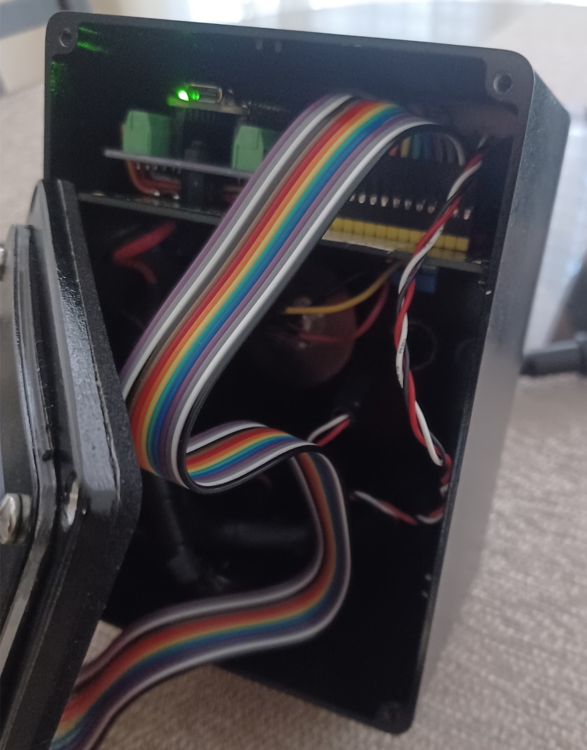
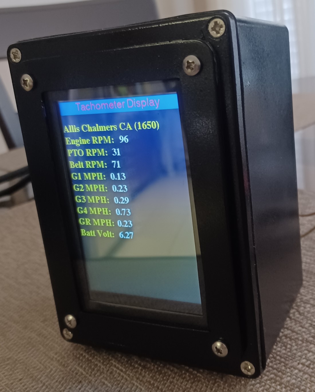
This is the "final" tach version (depending on how well it works installed). I still need to make the "power" harness (both harnesses will be cut to length on site). For this to work properly, the flywheel outer edge must be coated flat black and a single IR reflective strip will be applied. The reflective surface must be completely smooth to prevent spurious impulses. Depending on whether I can mount it close enough (< 2 inches) a plain white strip of tape or mylar will work. In testing, silver mylar worked slightly better, giving increased range and a stronger more consistent return. The width of the marker is to be determined. I'll start with 1 inch to provide a reasonable duration and reduce likelihood of missed pulses.
I also added a nice foam rubber gasket to the faceplate bezel and cleaned up the surround that was blocking some of the display pixels.
A view inside:
Reading the sensor through a 25 foot cable. Seems reasonably noise immune. Battery voltage is a tiny bit flaky. I tried to suppress noise but I should have probably tried a different noise suppression circuit design.
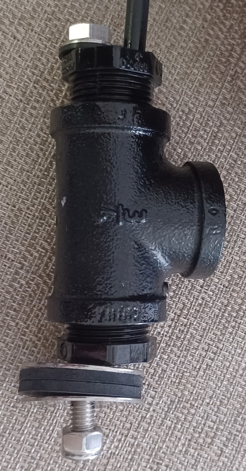
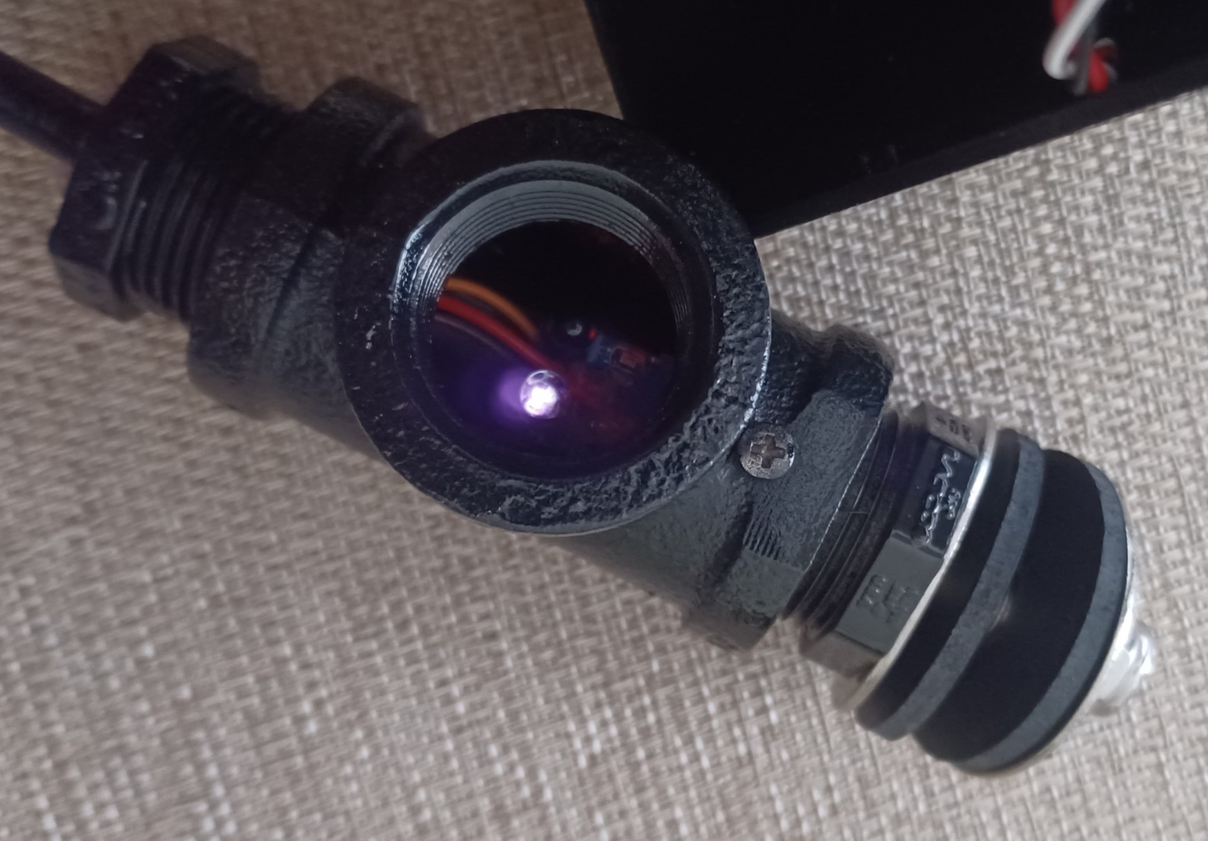
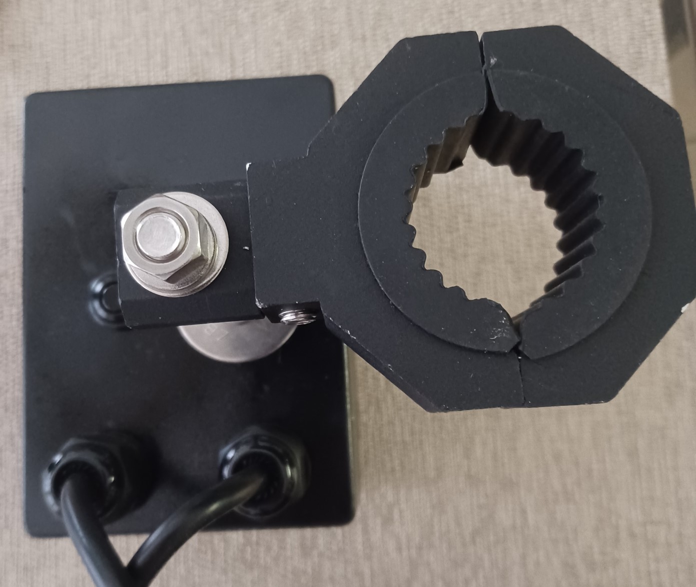
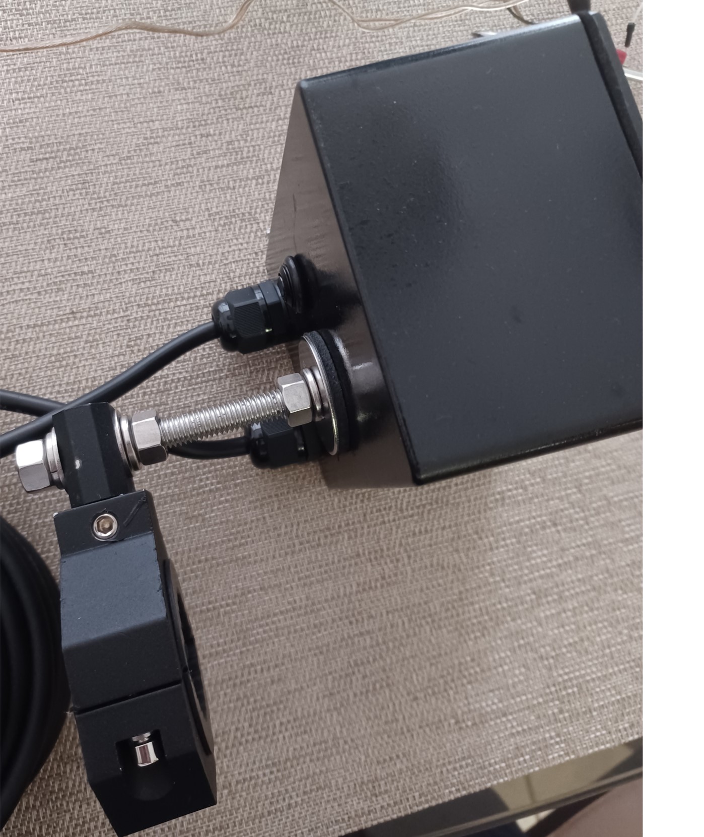
A side view of the sensor that will mount to the bottom of the bell housing through the loop in front of it (may need modifications on site).
A view of the mounted IR sensor inside the fitting.
A profile view.
A back view of the mount (repeat).
A view looking down at the back.
|
|
1952 CA13092
|
|
dfwallis
Orange Level
Joined: 09 Mar 2023
Location: DFW
Points: 609
|
Post Options
Thanks(0)
Quote Reply
Posted: 18 Aug 2024 at 10:41am |
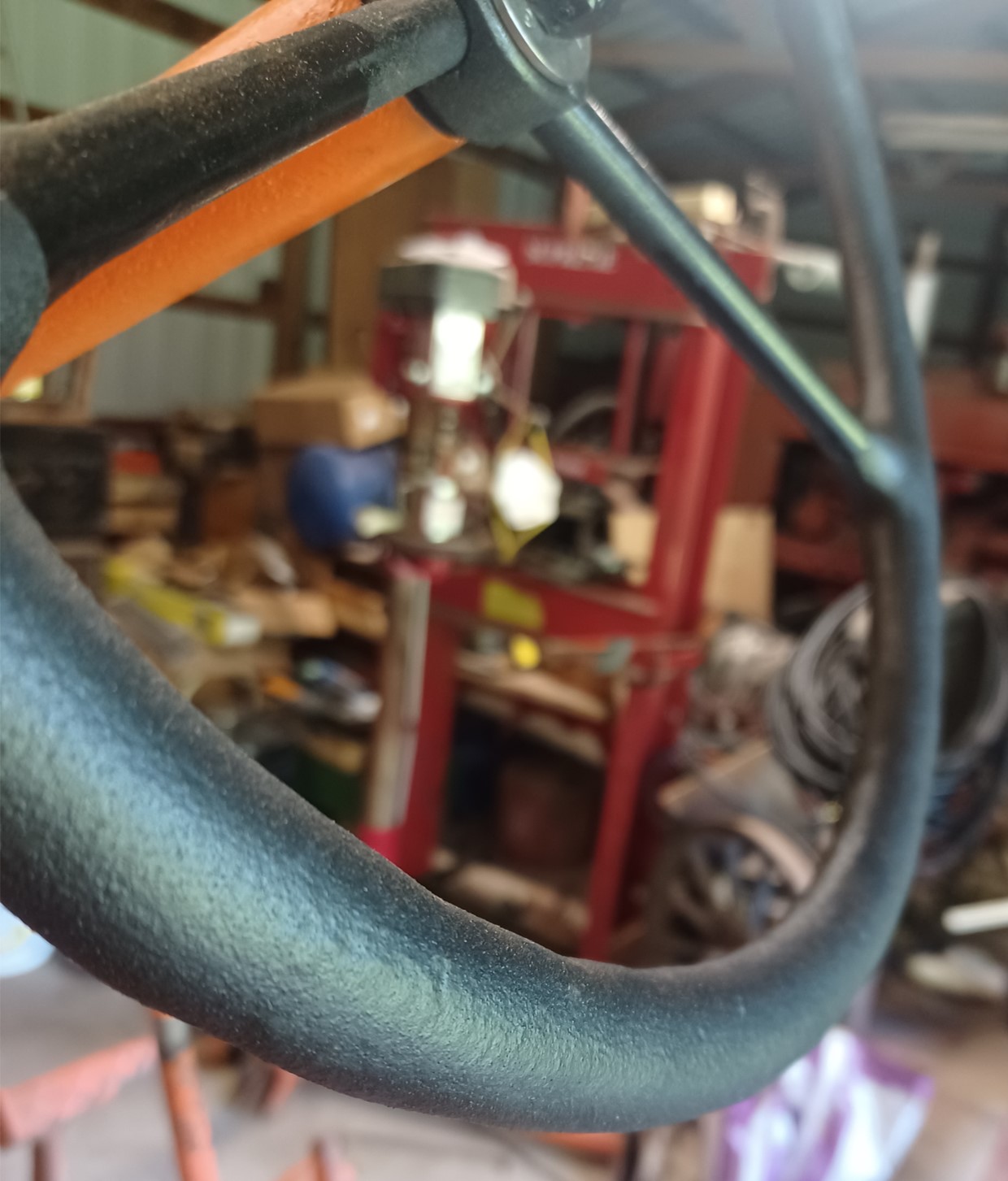
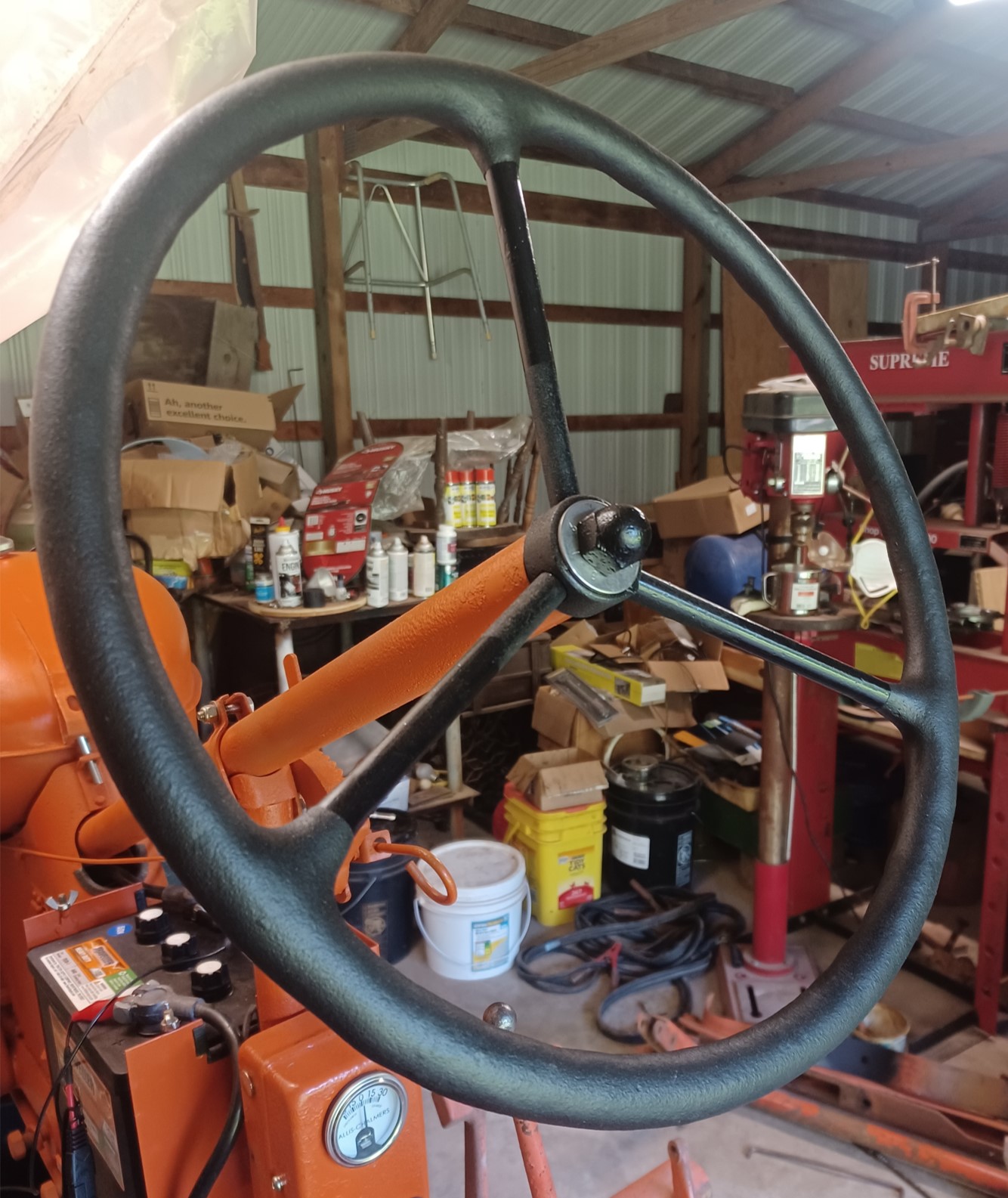
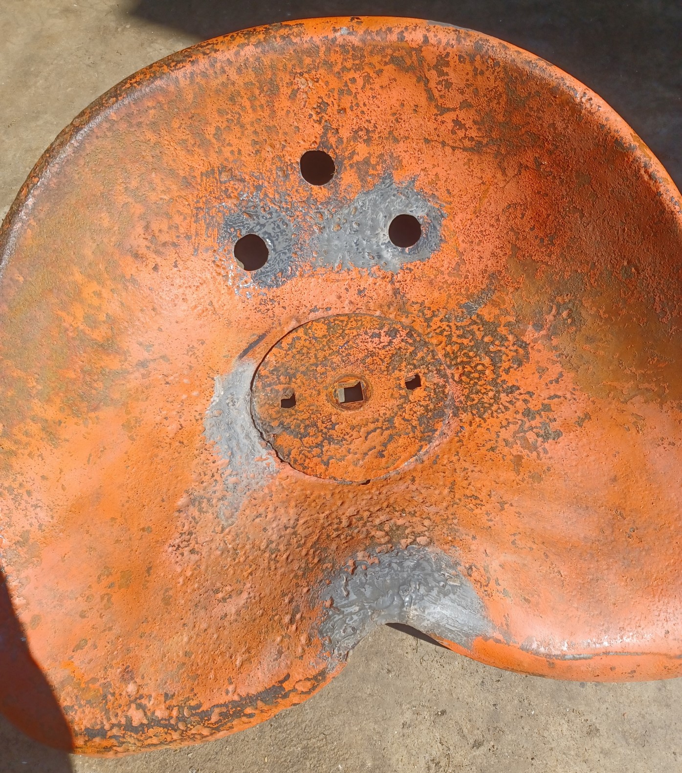
Here is a closeup view of the bed liner coating on the steering wheel.
Here is a full view. This coating is much tougher than the paint. I had used a very tough/hard paint, but I was worried it wouldn't hold up well. I think this will hold very well and has a good feel to it.
|
|
1952 CA13092
|
|
dfwallis
Orange Level
Joined: 09 Mar 2023
Location: DFW
Points: 609
|
Post Options
Thanks(0)
Quote Reply
Posted: 18 Aug 2024 at 11:03am |
The hand clutch release mechanism cleaned up and painted. The bearing and the throwout adjustment were both completely locked up. I had to use a large pipe wrench to loosen them up. The bearing was cleaned and greased and seems to function perfectly, although it does tend to settle outward a bit when not under load. In order to set the clearance, I had to use a screwdriver to force it together to get the gap tool inserted. I made two new lock screws (ground the tips to fit in the adjustment wheel grooves) and adjusted to just the right length to be able to lock them down.
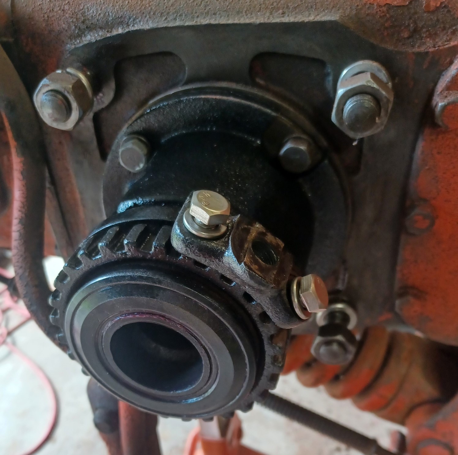
I was running out of time last trip so I decided to take the axle to the local (former) AGCO dealer for hand clutch repair. I was a little concerned because he did the repair (including religning and new springs/ball bearings) without removing the brake drum section from the axle. I bet that was difficult. In any case, there was little chance of actually testing/gauging the correct tolerances that way. After I got it back, I wanted to test it before I put everything back together. I had to put just enough structure together to operate the tractor (i.e. rails, brakes, seat). Initially it did not seem to be releasing. One thing that was concerning is that on at least 2 occasions, in attempting to release the clutch, a large cracking noise was heard, like a spring/ball seat popping into (or out of) place. This happened two times. After a final clearance adjustment, then the clutch started operating "correctly". It still has a slightly "off" feel to it, but my memories of using it are 50 years old. It does seem to be working correctly though as far as I can tell.
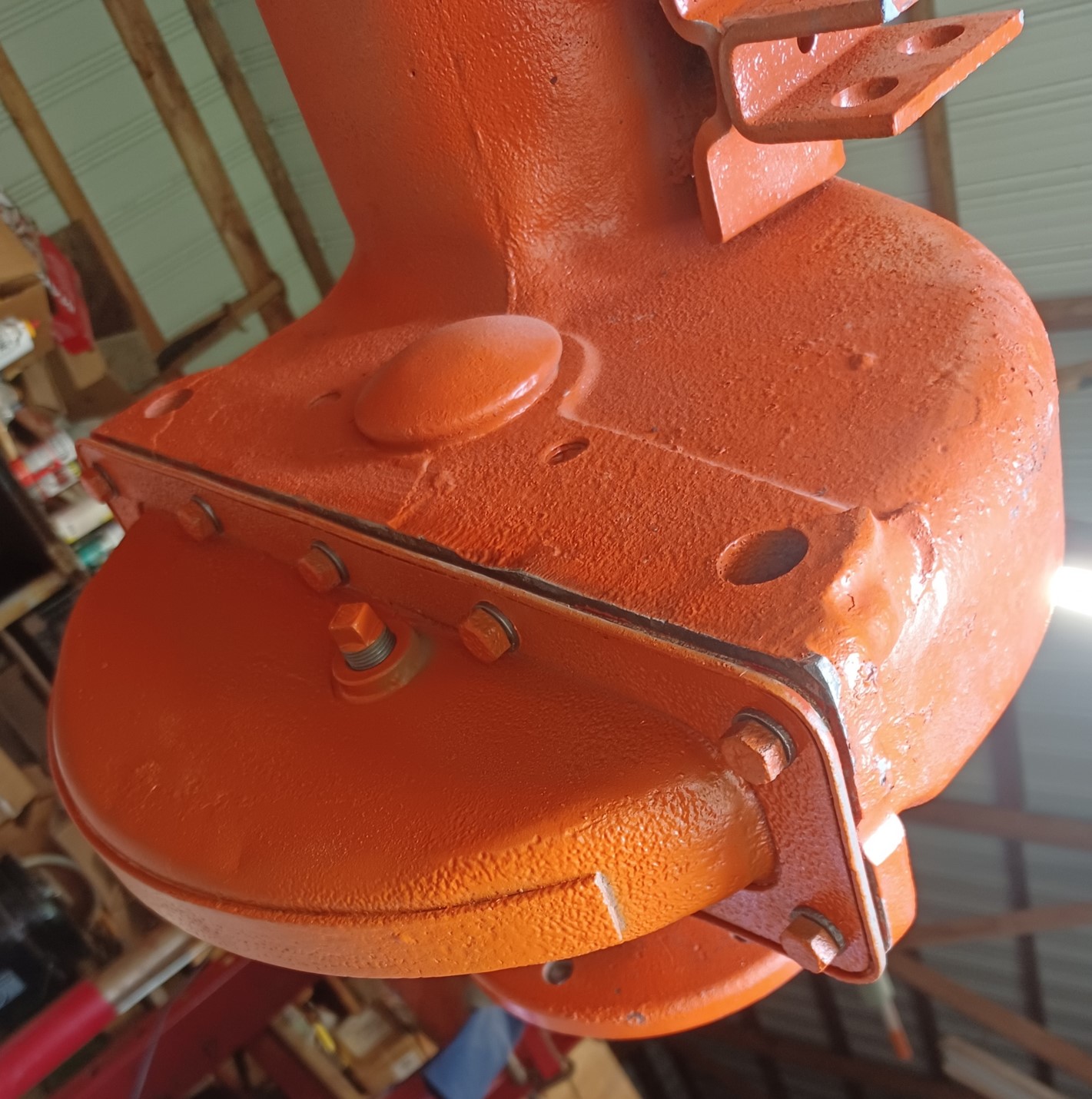
Installed the welded and POR15 sealed final drive oil pan. Added .75qt 80W90 gear oil...no leaks (yay). I will give the other (left side) one the same treatment later (not leaking but I bet it has some water in it like this one did). The rust pattern was weird...just needle sized pin holes with no rust surrounding the pin holes. How is that possible??
Edited by dfwallis - 18 Aug 2024 at 11:44am
|
|
1952 CA13092
|
|
dfwallis
Orange Level
Joined: 09 Mar 2023
Location: DFW
Points: 609
|
Post Options
Thanks(0)
Quote Reply
Posted: 18 Aug 2024 at 11:24am |
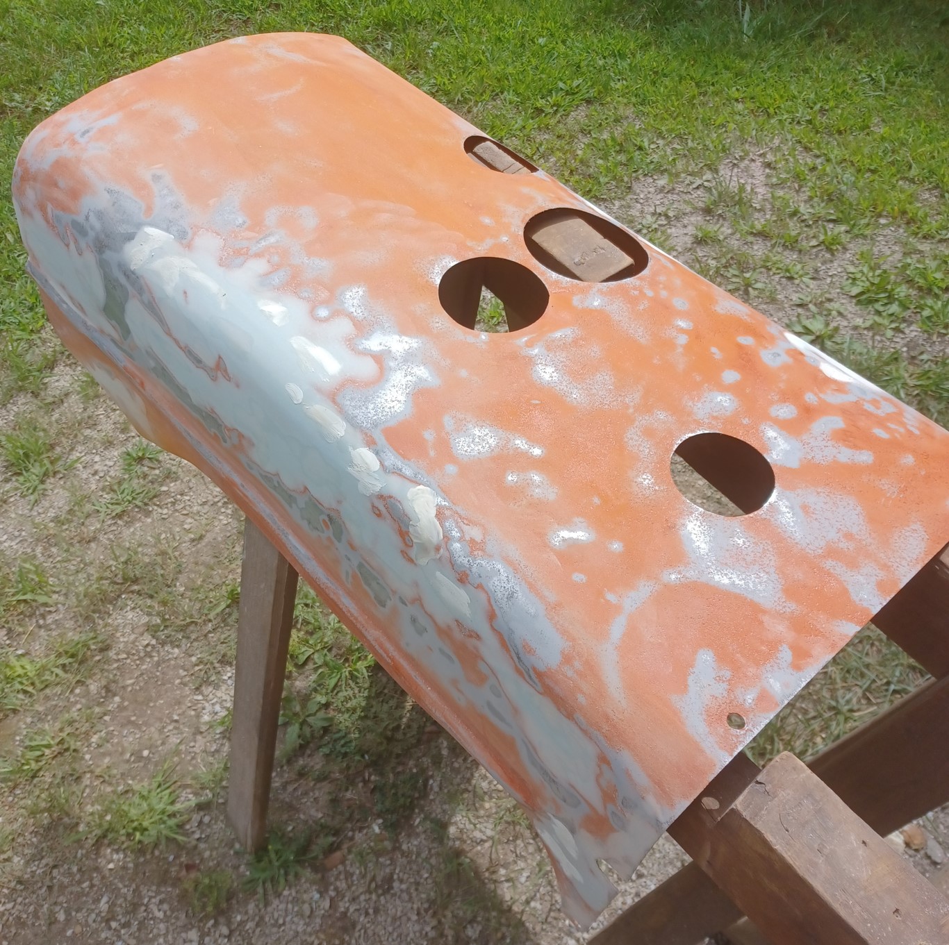
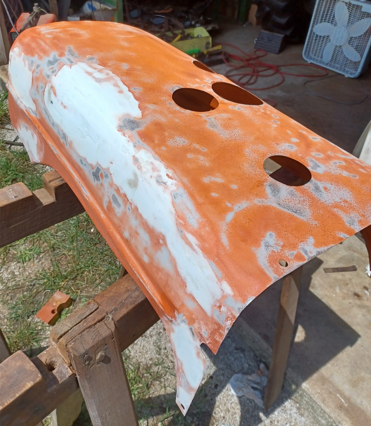
I spent days reworking the hood. It was severely damaged in a logging accident plus several hail events. I spent quite a lot of effort my prior trip but just wasn't getting the results I wanted, especially on the sides where the decals go. That was going to look awful. So I bought some body work tools and began pounding the heck out of it. Then I started bondo-ing the worst areas. I would have had to skim the entire surface to get it right. What a mess (not to mention the numerous rips and tears I welded). A sane person would have probably got new tin.
More bondo. Not clearly visible are the severe rust pits all over. Like the seat, some of the rust pits LOOK like they're deeper than the metal is thick :(
After 5000 coats of primer and days of sanding, I'd had enough (red deep fill primer). Good as it's gonna get.
Not really clear but the paint looks MUCH better this time. I had several issues previously:
1) Compressor was spitting out huge amount of water. To resolve, I purchased a 4 stage air dryer (which makes 5 stages given the one at the compressor). This made a massive difference for both painting and sand blasting. After i got the sand blaster cleaned out of all the hard chunks/flakes of sand, it was greatly improved in performance.
2) Massive bugs and tree residue (in May), plus a lot of rain adding to the compressor moisture issues.
3) I was following the directions on the Tallman's paint can previously. This time, I used the advice of "random internet guy" and mixed hardener and naphtha thinner in a 4-1-1 ratio. This massively improved the paint drying time, hardness, and gloss.
Edited by dfwallis - 18 Aug 2024 at 6:51pm
|
|
1952 CA13092
|
|
dfwallis
Orange Level
Joined: 09 Mar 2023
Location: DFW
Points: 609
|
Post Options
Thanks(0)
Quote Reply
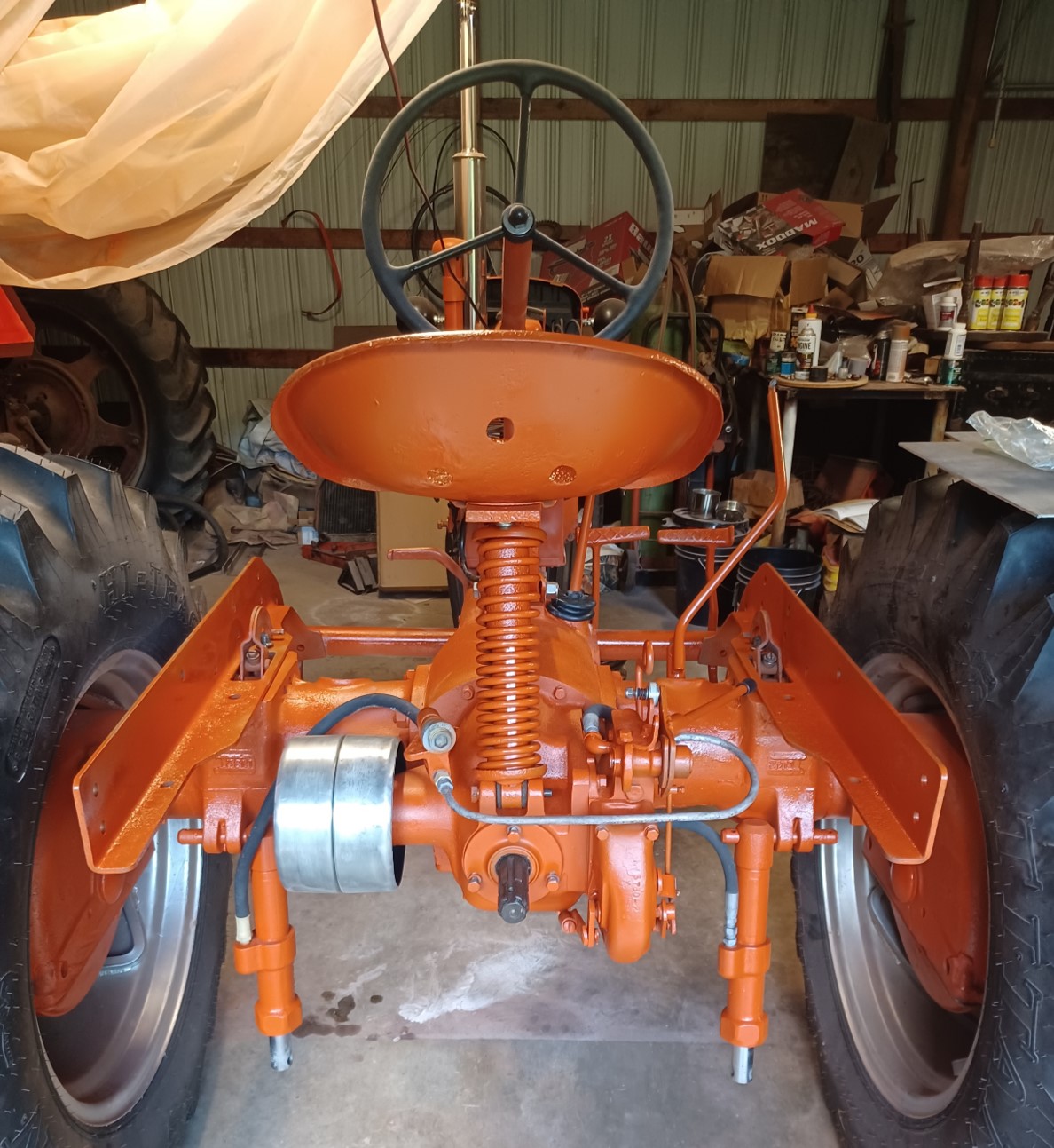
Posted: 18 Aug 2024 at 11:38am |
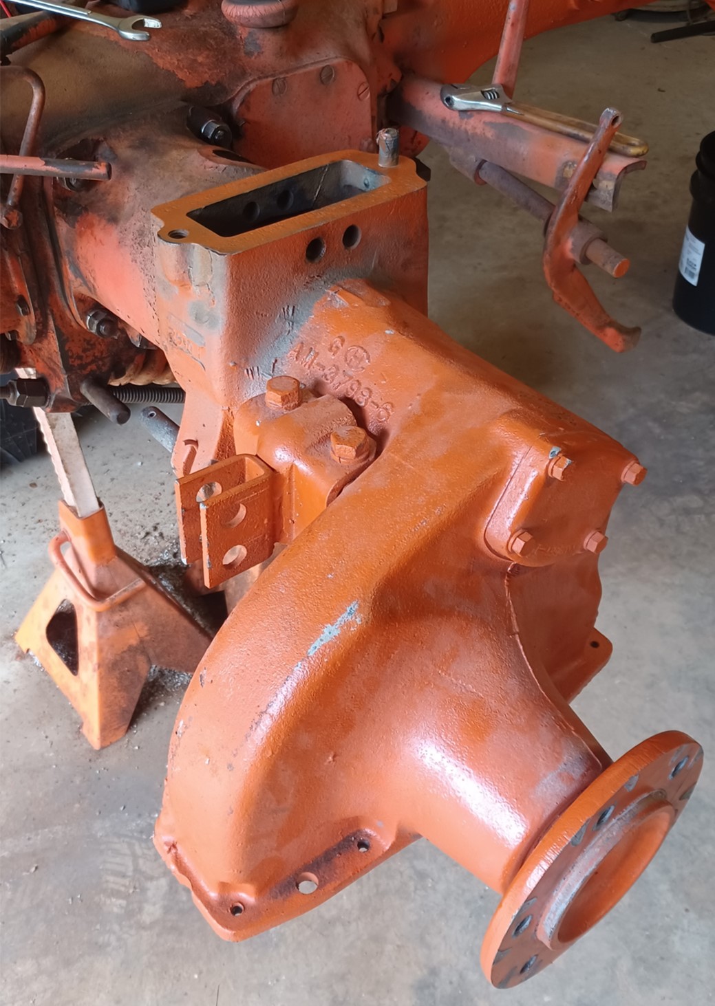
A view of the rear end sand blasted and painted. It has 3 coats of primer and 3 coats of color. I bought a nice black seat cushion to cover up the crusty seat :) If I had had another few hours this trip I might have installed the rest, but paint recommends waiting 7-10 days to let the paint cure. Here I just installed what was necessary to test the hand clutch. I also drained and put new gear oil in the tranny. Overall, given that the hand clutch SEEMs to be working, I'm happy with my progress this trip. A lot of progress in 6 days. Even spent some time with my brother trying to get the M running :) One problem I still have is that the governor seems to only bring the speed up to 1/4 throttle. The throttle rod was "straightened" to just one bend just behind the starter and now gets me full range of the control mechanism minus 1 notch (was 4 notches short before...it starts bending the rod at the last notch now). I can probably work the bending of the rod a little more and get the full range of the control correct.
I'm guessing that the governor spring is weak, but it doesn't look to be stretched.
The hydraulic hoses are split and frayed, I guess I'll try to replace those (hopefully I can find some swivel fittings that don't leak, I don't like the way they have to be twisted as-is).
I also cleaned up and removed some large dents in the belt pulley last fall and just installed it.
Edit: An interesting note is that both of the hydraulic cylinders were originally rusted solid in place (in the drawbar pin position). I could actually stand on them and jump up and down and they absolutely would not budge up or down. It took weeks of soaking and prying to get them loose.
Edit: I've decided that I have the throttle "surge" spring installed incorrectly and that is the likely cause of the throttle control issues.
Edited by dfwallis - 21 Aug 2024 at 8:11pm
|
|
1952 CA13092
|
|
dfwallis
Orange Level
Joined: 09 Mar 2023
Location: DFW
Points: 609
|
Post Options
Thanks(0)
Quote Reply
Posted: 18 Aug 2024 at 11:43am |
Tachometer project status update 8/18/2024:
As expected, I need to make two tiny mods.
1) The sensor housing itself (plumbing T) was cut to the correct dimensions. But this will require me to mount the sensor on the opposite (rear) side and change the entry point of the cable (no big deal).
2) The display housing needs about 1 inch more clearance to deconflict with the throttle and starter control rods (expected). (also need thinner rubber clamp mounts since the steering column diameter is larger than I remembered).
|
|
1952 CA13092
|
|
dfwallis
Orange Level
Joined: 09 Mar 2023
Location: DFW
Points: 609
|
Post Options
Thanks(0)
Quote Reply
Posted: 18 Aug 2024 at 2:09pm |
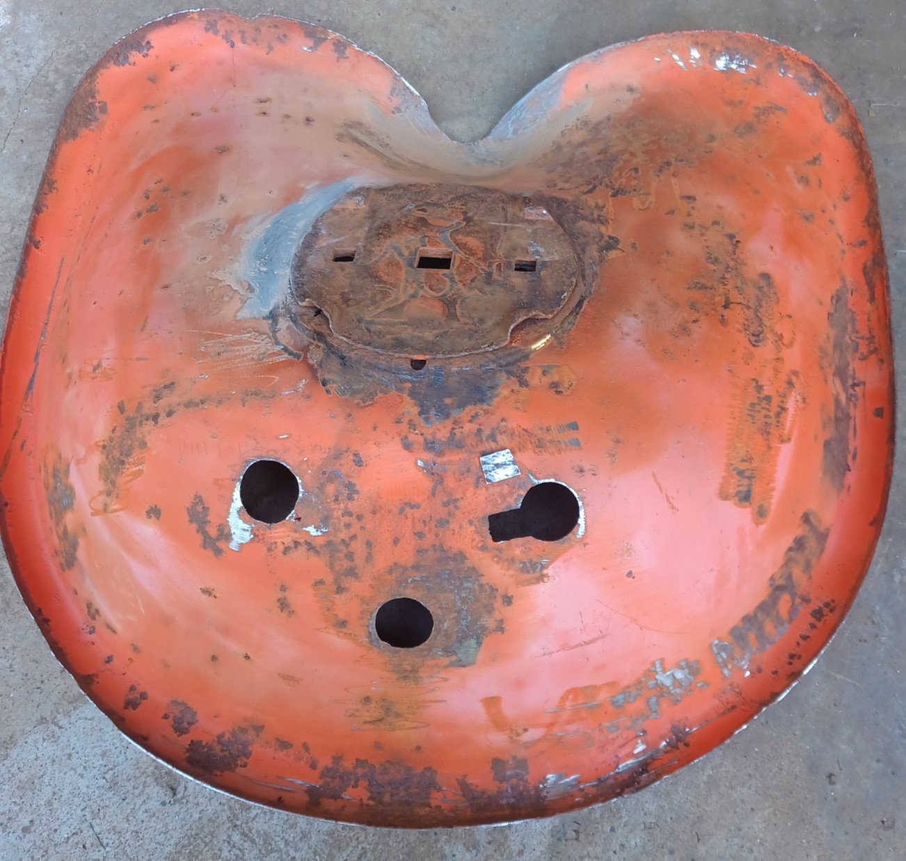
Showing where the seat was rusted through and welded and epoxy skim coated. I originally didn't plan on fixing the hole, but decided to go ahead. It came out nice and round-ish. It was sand blasted further before painting but I didn't get a good post paint pic (but you can probably imagine painted rust pits well enough).
Those are some DEEP rust pits.
|
|
1952 CA13092
|
|
CA13414
Silver Level

Joined: 25 Feb 2024
Location: Nebraska
Points: 260
|
Post Options
Thanks(1)
Quote Reply
Posted: 18 Aug 2024 at 8:55pm |
|
Your painting looks awesome. You are definitely more OCD than me in that regard. I was like.... one coat of primer is enought.... lets paint!!
Your work is looking awesome!
|
|
Helping the aged survive and thrive! 1953 CA
|
|
dfwallis
Orange Level
Joined: 09 Mar 2023
Location: DFW
Points: 609
|
Post Options
Thanks(0)
Quote Reply
Posted: 22 Aug 2024 at 10:50am |
Tachometer project status update 8/22/2024:
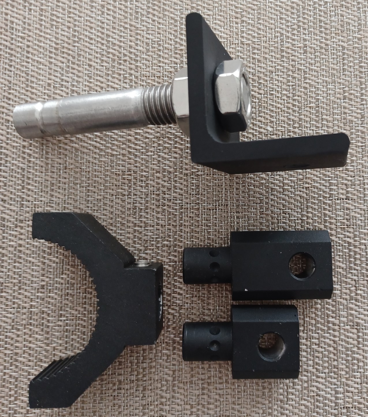
Installation clearance modifications:
The tube clamp actually came with a slightly longer extension that I didn't remember. If that one isn't long enough, I've made one that gives me much more flexibility. I added a continuous groove for the pointed set screws to sit in to reduce the chance of accidentally pulling out. There will be lock washers in addition to the jam nuts.
The original clamp extensions only came with fixed set-screw positions. If needed, I can similarly groove it given that it's unlikely that the fixed positions will give the correct angle for the display.
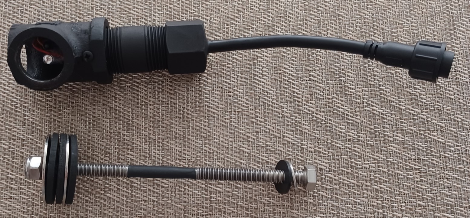
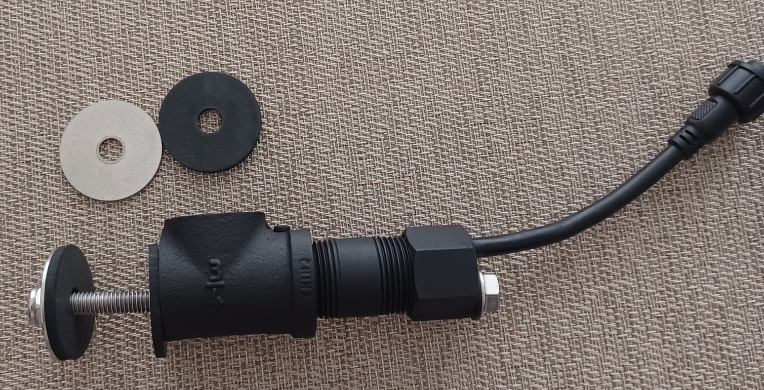
The sensor itself had to be cut to fit the opening at the bottom of the bell housing and the mounting ring just in front. This required me to add an extension on the back side in order to provide enough clearance for the wiring harness. The pipe nipple was grooved on the end to allow the PCB screw to mount correctly. The nipple also decreased the clearance between the through bolt and the PCB so I ground a clearance in the middle of the through-bolt and covered it in shrink wrap tubing. There should be enough clearance, this was just a precaution.
There will be a shortened nipple protruding upward into the bell housing hole to prevent rotation. The exact rubber sealing arrangement is tbd. I intended to use gloss paint, but my last can of gloss black stopped spraying properly before it ran out of paint (broken button receptacle in the can)...:(
|
|
1952 CA13092
|
|
dfwallis
Orange Level
Joined: 09 Mar 2023
Location: DFW
Points: 609
|
Post Options
Thanks(0)
Quote Reply
Posted: 03 Oct 2024 at 12:09pm |
September status update part 1 (10/03/2024):
My first completed task was to re-bend the throttle control rod to get the full range of motion for throttle control. After about 6 attempts I got it to within 1 notch. To get the remaining notch, I shortened the metal insert in the governor spring. I took 1/32 inch off each end which allowed me to reach the first idle detent. This should not have been necessary, but I was unable to get the linkage bent exactly right and shortening this insert was the most obvious "fix".
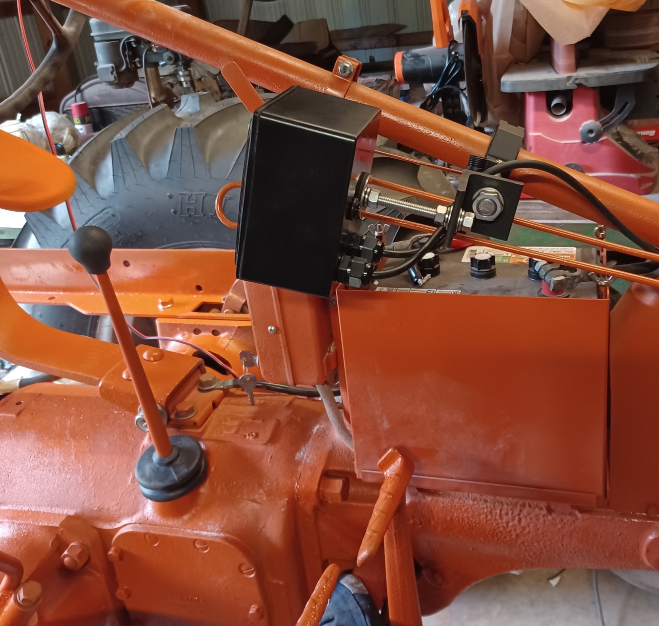
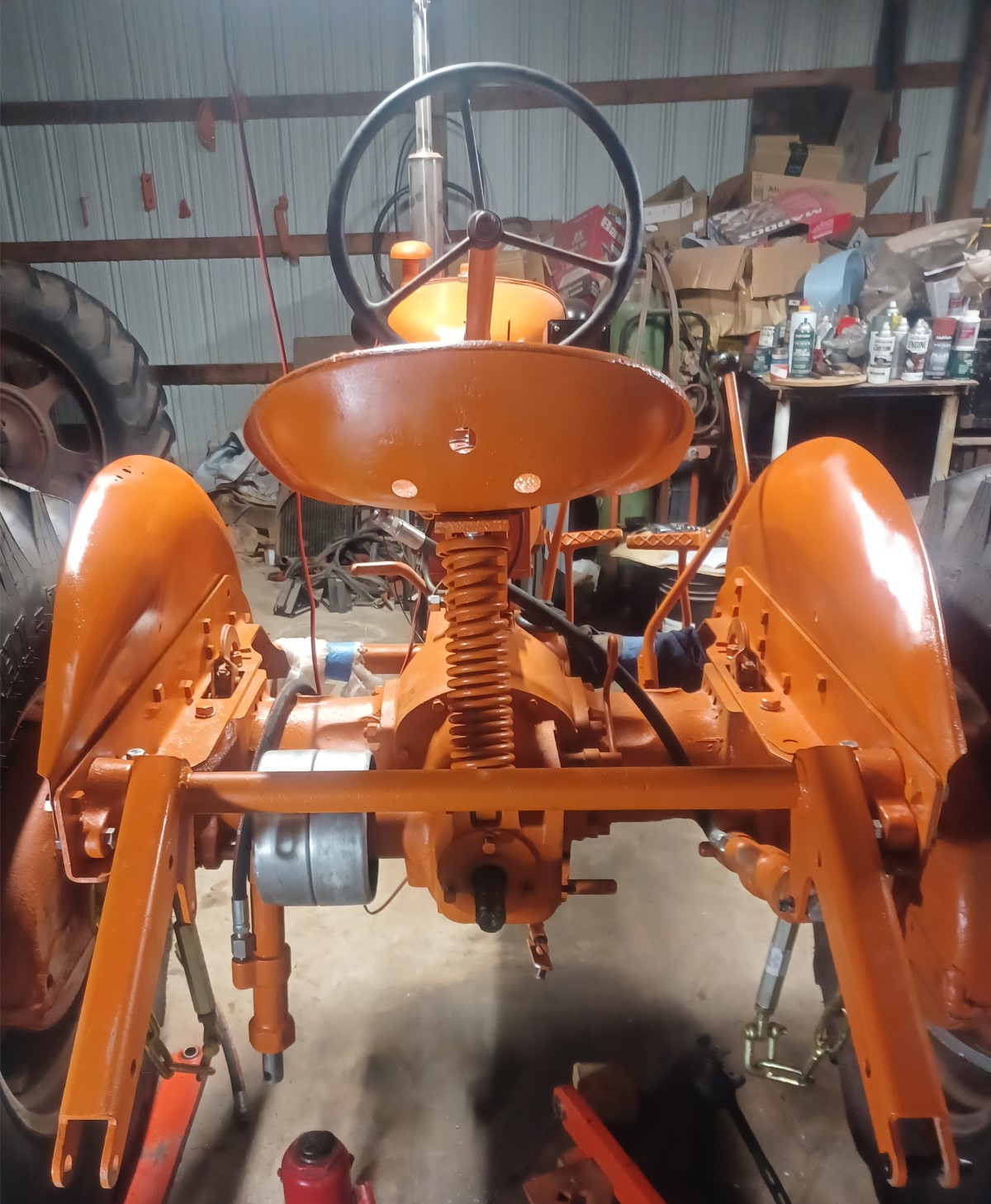
I then switched to run wiring and install the prototype tach and sensor. It has not been wired yet but I routed the wiring along side the battery cable and exited the bottom hole at the front of the tool box.
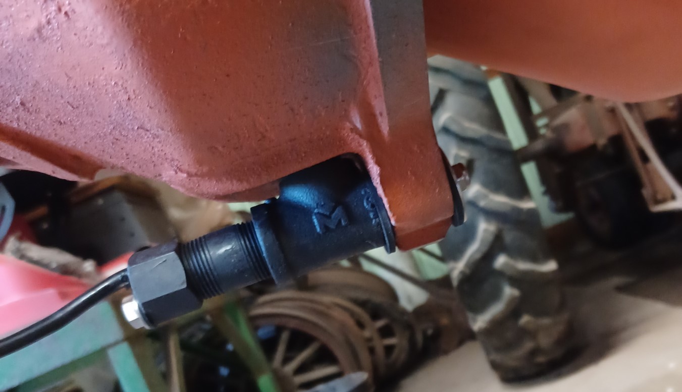
The sensor is installed at the bottom inspection hole on the bottom of the bell housing. I still need to coat the outer flywheel with flat paint and a suitable reflective marker, perhaps at the "fire" mark. Completing the tach install isn't on the high priority list at the moment. Given my earlier problems with the DMM going haywire due to the ignition noise, I'm a little concerned whether the tach will be sensitive to that noise. I've not provided a filter on the power supply input (not too hard to add i suppose).
Front view. I think it will be adequately out of the way of the controls, but can be moved further back if needed.
Edited by dfwallis - 03 Oct 2024 at 2:24pm
|
|
1952 CA13092
|
|
dfwallis
Orange Level
Joined: 09 Mar 2023
Location: DFW
Points: 609
|
Post Options
Thanks(0)
Quote Reply
Posted: 03 Oct 2024 at 12:51pm |
September status update part 2 (10/03/2024):
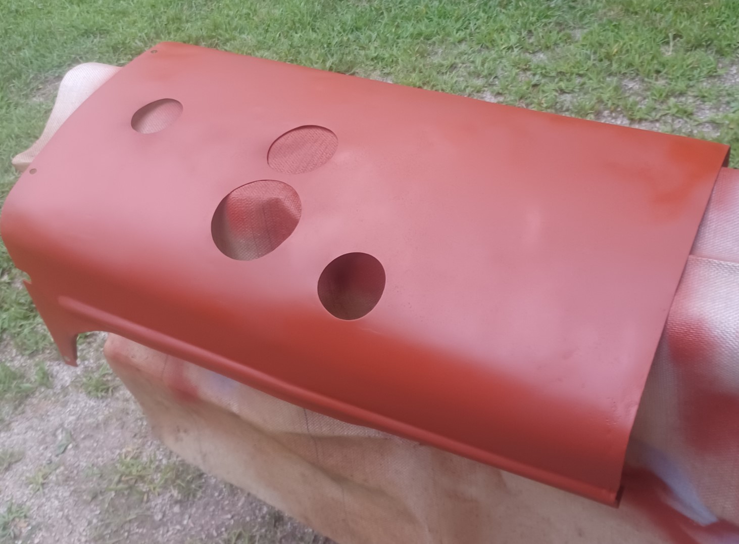
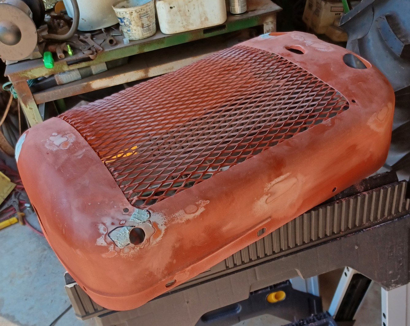
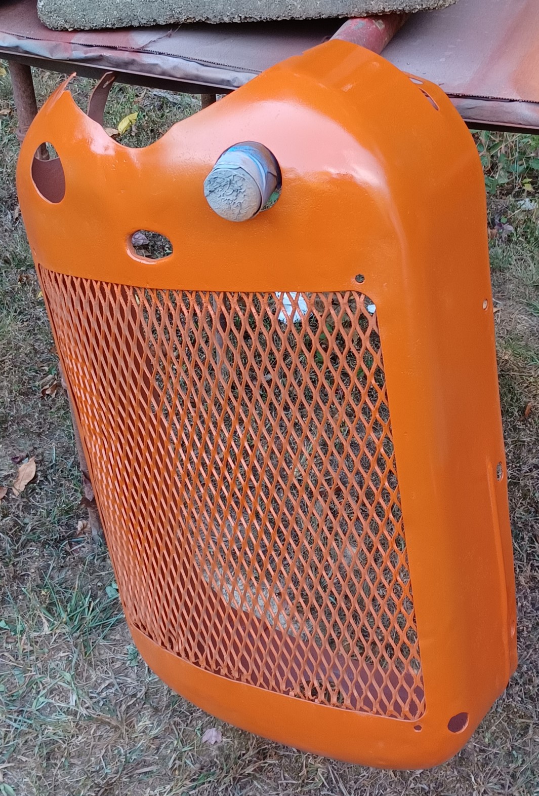
I reworked the gas tank and hood/cowling on the June trip. Before installing those items, I decided to rework the grill (due to unsatisfactory paint/compressor performance and the hundreds of hail-like dings and rust pits all over). I had purchased a set of body-work tools in June and that helped me significantly improve the tin, along with selective application of bondo.
It turned out quite a bit improved. Not perfect, but about as good as I could do in the limited timespan (and inadequate conditions).
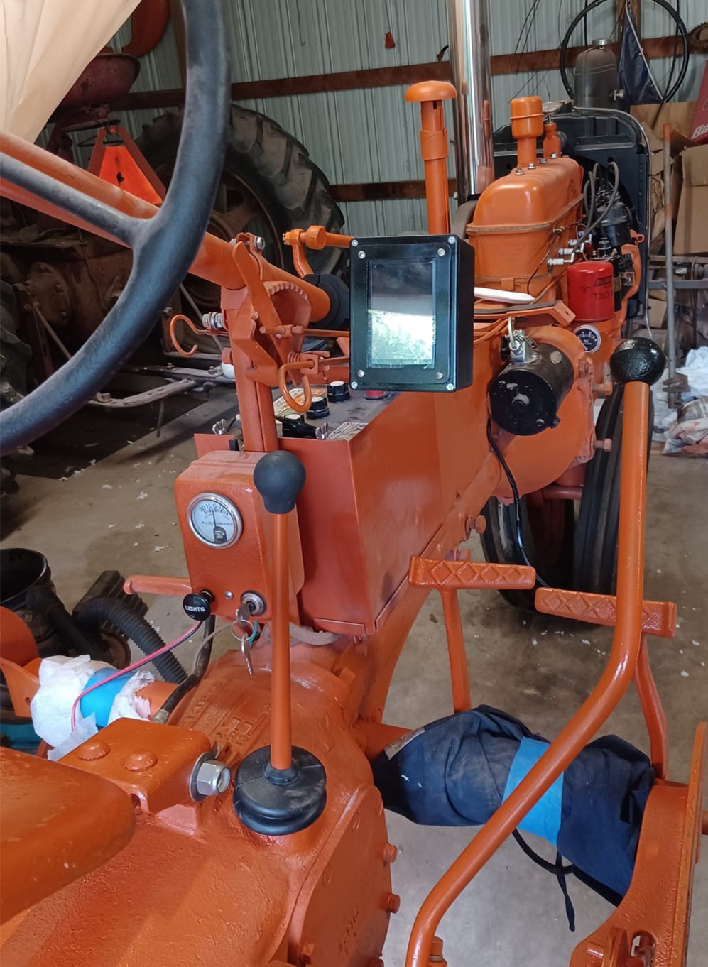
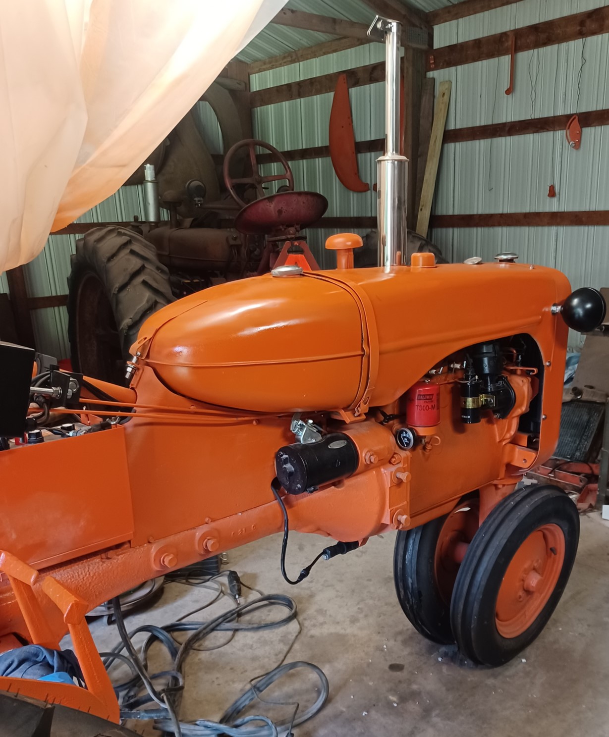
Initial install of gas tank and tin. There remains some issues, but I think it will be acceptable. The new radiator (claimed for a CA) was not correct and had to be modified to match the tin mounting holes. So there was some very slight misalignments that you can see if you look closely. Also, I added fabric on the tin and strap where the 3 pieces strap together. The fabric appears to be ever so slightly too thick and (coupled with tin warpages) made the mounting strap bolts about 1/8 inch short of needed to start the nut. It took quite a bit of stretching to get everything pulled together. Another contributor may have been the gas tank repair. The severe crush damage from a logging accident was repaired (dents pulled out filled with epoxy and bondo) and the surface curve may have been ever so slightly too high. It doesn't take much error to lengthen the strap requirement. The tin crease doesn't align properly with the gas tank on the opposite side, most likely due to the gas tank repair.
Edited by dfwallis - 03 Oct 2024 at 12:52pm
|
|
1952 CA13092
|
|
dfwallis
Orange Level
Joined: 09 Mar 2023
Location: DFW
Points: 609
|
Post Options
Thanks(0)
Quote Reply
Posted: 03 Oct 2024 at 1:34pm |
September status update part 3 (10/03/2024):
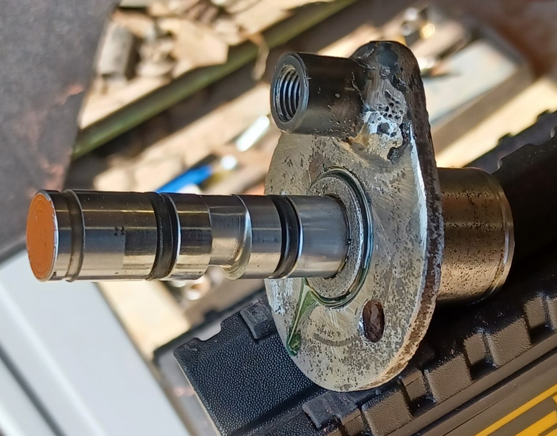
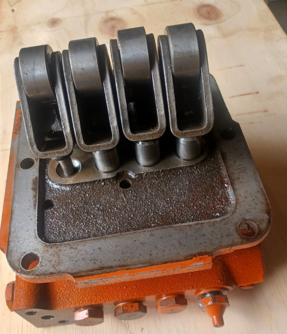
Next I moved to hydraulic pump testing. First I replaced the badly fraying 72 year old hoses with new 5000psi hoses. I began testing the pump behavior and found it to be quite noisy and there was no attempt to pump at all. After investigating, I discovered that one of the plungers was stuck depressed.
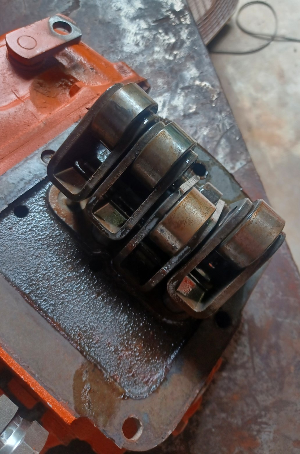
I began by disassembling all of the external parts (hold valve and control mechanism, and pin that holds the rollers for the plungers) and soaking the piston in penetrant and every now and again I'd walk by and tap it. After a day or so, the piston suddenly popped up (to my great relief). I then began a full disassembly and cleaning (mostly varnish, very little rust). I replaced all of the check balls most of which were severely corroded on the spring side (the springs were not though) but showed irregular shape on the seat side. The seats themselves all seemed ok as far as I could see. I also discovered that the main control valve spring had been broken and someone had intertwined two springs together (which risked gouging the bore but did not seem to have). Not knowing the characteristics of the original spring, I couldn't tell if they simply intertwined the broken half with the original spring. The intertwined spring was about 2/3 the length of the main spring. The mechanism of actuation of this plunger and spring isn't clear to me. The main (broken) spring was way longer than the plunger tip would require and provided considerable force that made it a little challenging to compress to get the clip off, so I'm not sure whether function was compromised or not.
End result is that the pump was still not functional after my cleaning and reassembly. It was much quieter operating (near silent) due to the stuck piston being freed. I made another 3 attempts at cleaning and reassembly, carefully following the inadequate documentation I had (a WD schematic which was said to be similar enough to a CA). Given it was taking a considerable amount of my limited trip time, I elected to take it to the former AGCO dealer to work on. He has not reported finding any issues yet, after a week. There was some question as to whether there should be a check valve on the inlet as some images on the web seem to show. I was unable to research at the time due to poor cell and internet access, but later determined that beginning with CA17441 and up, a check valve was added to the inlet. So mine never had one (CA13092). CA17441 is in the same year as mine (1952). I can only guess that there was some sort of issue with priming or holding prime that was addressed.
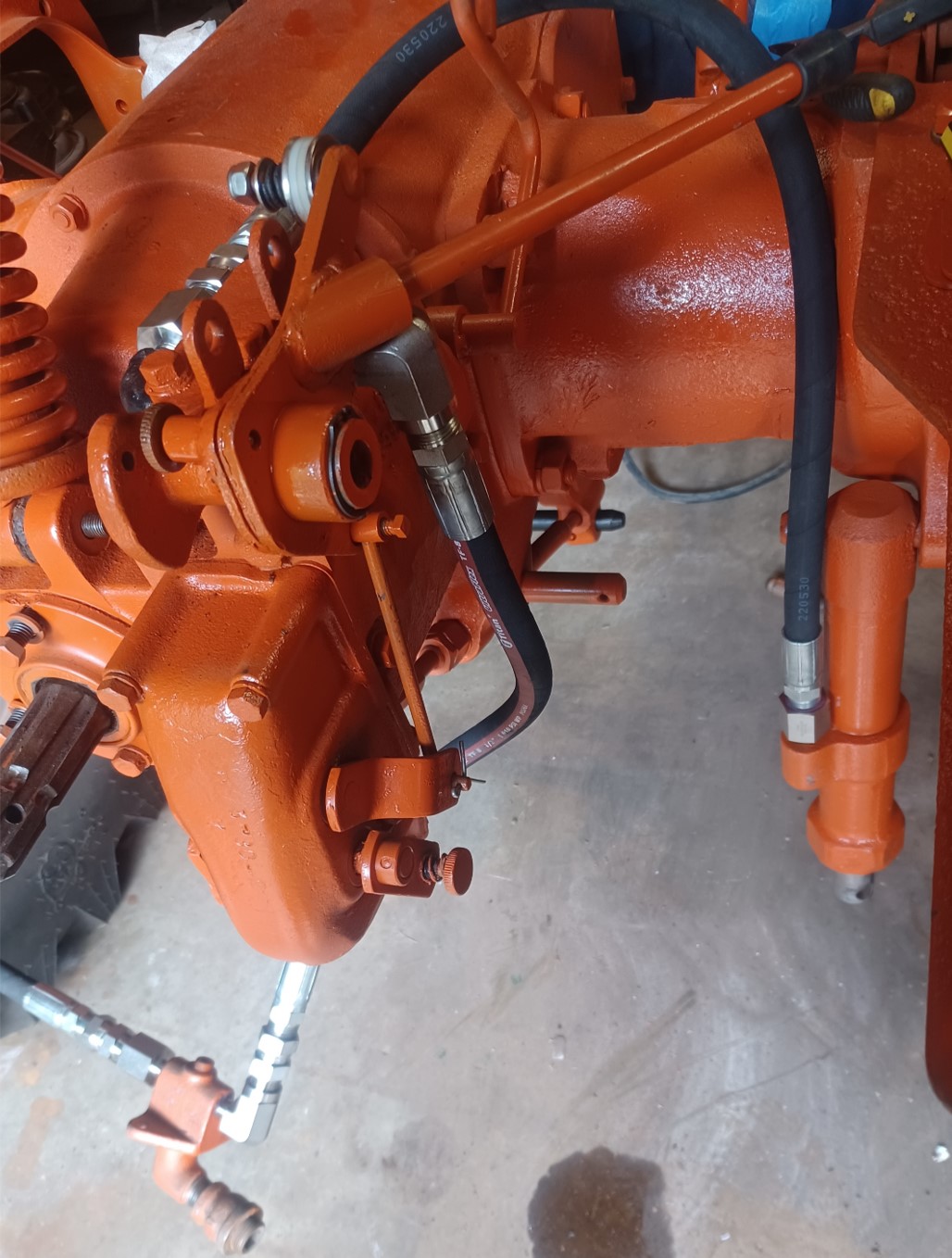
Installed new hydraulic hoses. I may have some sharp bending issues to address. Unfortunately, it seems impossible to install a 45 or 90 fitting on the cylinder itself due to insufficient clearance. I may be able to use swivel adapters I guess.
Dad had presented me with a broken off screw and nut but I didn't know initially what it went to. It turned out to go to the hold valve plate. So I was able to weld it and clean it up. A problem arose however when I tried to separate the two plates. They were firmly rusted together, both the bearing and the plates themselves. During my (I though careful) attempts to separate them, the press fit plate separated from the bearing. After researching, hopefully I got the orientation correct. It should be obvious if not once I'm able to get the pump working. I reinstalled as a press-fit item (it liked the assumed correct orientation and resisted rotation about that position), so I used a punch to pinch it back together coupled with some loctite metal-metal bonding glue. I also replaced the detent ball which was in bad shape.
Not sure why so fuzzy. I guess I was too close.
Edited by dfwallis - 03 Oct 2024 at 6:22pm
|
|
1952 CA13092
|
|
dfwallis
Orange Level
Joined: 09 Mar 2023
Location: DFW
Points: 609
|
Post Options
Thanks(0)
Quote Reply
Posted: 03 Oct 2024 at 1:44pm |
September status update part 4 (10/03/2024):
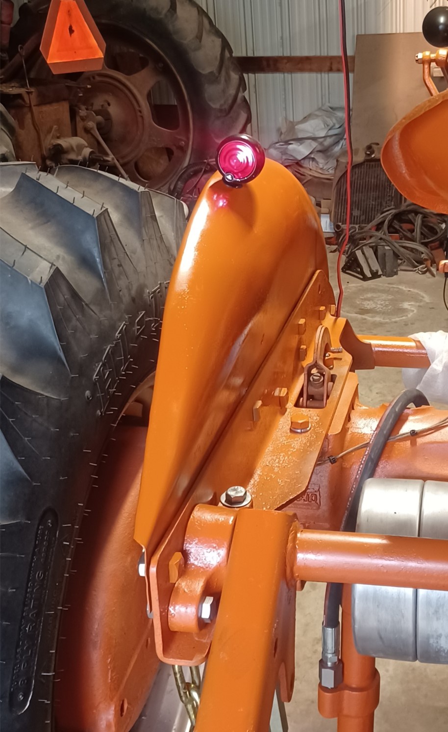
I next installed the fenders. Somehow, I miscounted the number of square head bolts to order by exactly 1 (or I received 1 too few) so I've ordered some extras to finish up next trip.
I wired and painted the bullet light on the left fender. It came unpainted. I added a wire tie down point to attach the wire tie to below the seat mount. Otherwise, they could move around and get pinched. I routed a second wire to use for a potential spot-light. Given that I have two free light switch positions (due to adding a regulator), I have some additional lighting opportunities.
|
|
1952 CA13092
|
|
dfwallis
Orange Level
Joined: 09 Mar 2023
Location: DFW
Points: 609
|
Post Options
Thanks(0)
Quote Reply
Posted: 03 Oct 2024 at 2:15pm |
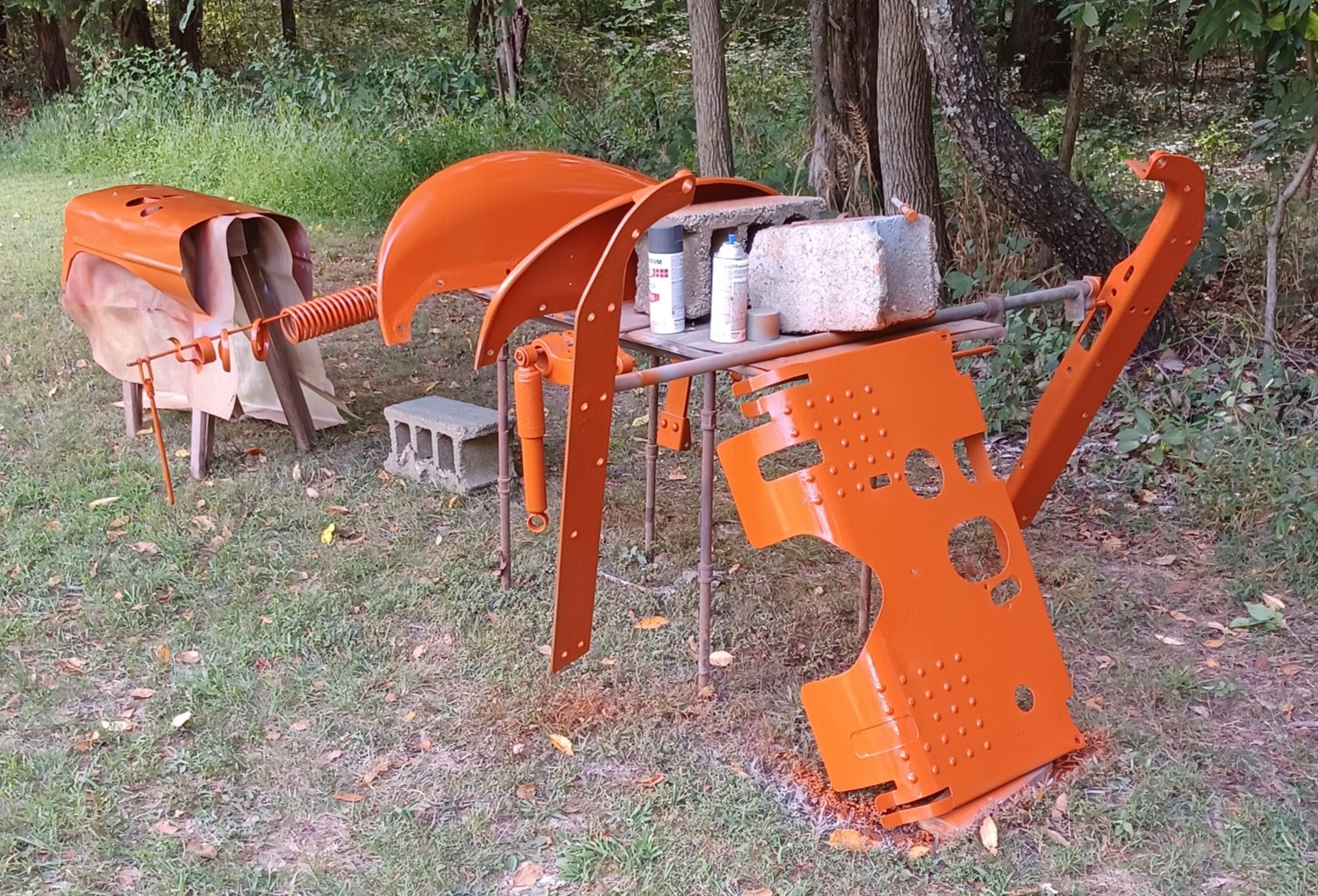
September status update part 5 (10/03/2024):
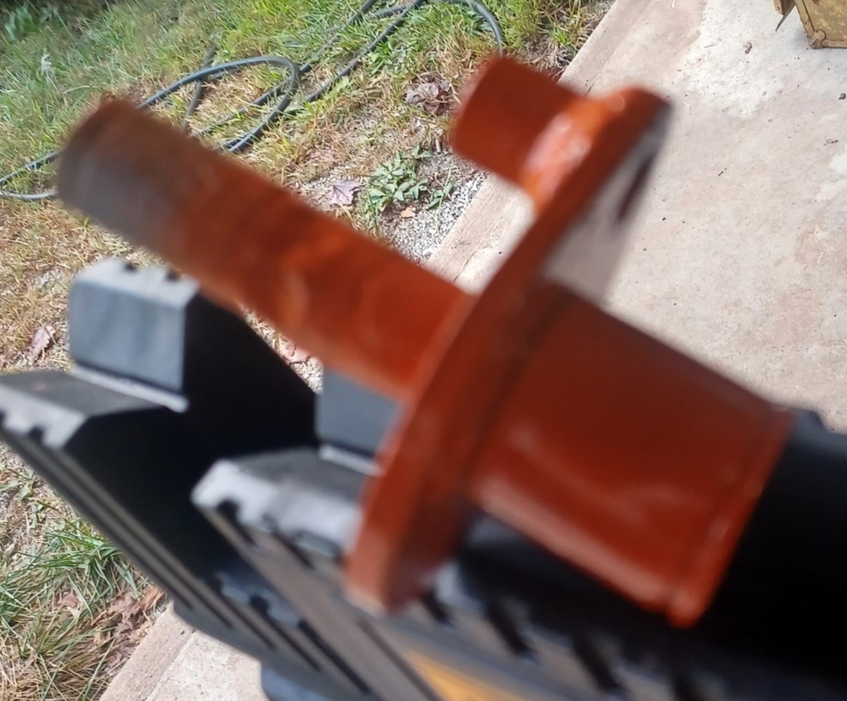
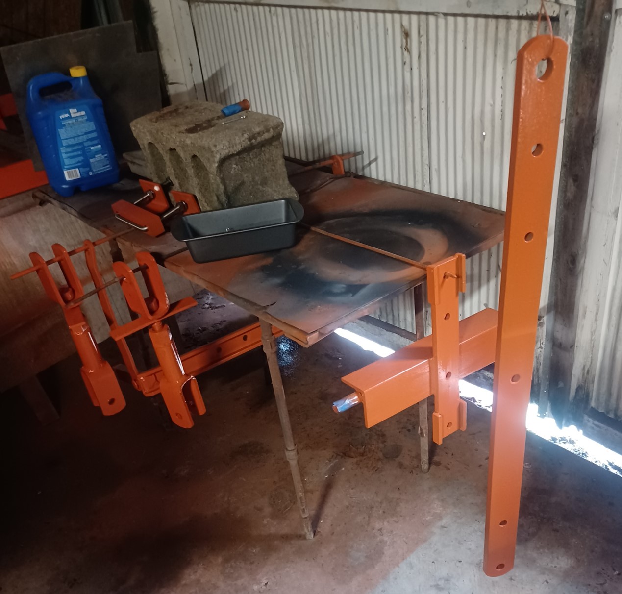
The Cross Mfg 3-point kit comes in an ugly red color so I cleaned up and repainted the drawbar and the kit. Since it was raining virtually the entire 2nd week, I had to do everything indoors. I hope I didn't get any orange paint on that red tractor right behind this location :). Getting the kit ready to install was not a small task. In order to fit it to the pin-hitch CA, I had to create a new bail system to free the old bail from the lift arms (mostly designed and built two years ago). That required cutting the new bail to length and drilling what seemed like hundreds of holes. Unfortunately, my newly acquired chop saw flopped massively on the 1 inch thick steel. I had to finish it up with an angle grinder with cutting blade. I think it was due to the specific blades i bought which indicated for stainless. I think the grain was just too fine. I have new blades for next time.
Earlier I had questioned the lift arm lower height requirements which I feared I might not make with this design. However, I developed some "floating" attachment accessories which get me from 10.5 inches down to 7.5 inches which I think should be enough. The reason for the relatively high lower limit of 10.5 inches is because I left the original bail attached to the drawbar and it interferes somewhat (also, I installed 13.6 tires). This was so that i can "rapidly" reconfigure back to the pin-hitch configuration. It also provides some sway stabilization. However, if I need to go lower than 10.5 inches or 7.5 inches with the "floating" attachments, I can always remove the old bail. That will allow the lift arms to go to the ground. The only physical mod to the drawbar was to increase one hole size from 9/16 to 5/8 and to drill one new 5/8 inch hole near the front for the 3-point arm mount. I also added two inches of rise to the Cross lift arm mount via two long plates beneath it. This helped better clear the old bail with the lift arms. I haven't weighed it yet, but I'm guessing the new 3-point mods add about 300lbs of weight. The new bail itself is just about my limit of being able to pick up and align in place to the tractor. Most of the weight will be within a foot of the axle. I also bought some new sway stabilizers from TSC that consist of a turnbuckle and a heavy duty chain. I modified the eye-bolt very slightly to better fit the axle pins that the rock shaft/fender rail stabilizers attach to (ground the inside where the bolt is angled and made the eye-bolt very slightly thinner to allow the clip to attach more freely as the eye-bolt rotates with tension on the chain).
Edited by dfwallis - 04 Oct 2024 at 9:41am
|
|
1952 CA13092
|
|
ACinSC
Orange Level
Joined: 16 Dec 2015
Location: South Carolina
Points: 2737
|
Post Options
Thanks(0)
Quote Reply
Posted: 03 Oct 2024 at 2:18pm |
|
Looking good!!
|
|
dfwallis
Orange Level
Joined: 09 Mar 2023
Location: DFW
Points: 609
|
Post Options
Thanks(0)
Quote Reply
Posted: 04 Oct 2024 at 2:52pm |
September status update part 6 (10/04/2024): I also finally timed the engine and adjusted the idle mixture again. It was running much better but it seems like the idle mixture needs to be re-adjusted to run well at a given temp. These changes greatly improved the cranking performance of the battery. So it was just firing way too early before. If I remember to turn the gas back on, it fires and runs instantly now. It still does have an occasional "pop"/misfire. This was greatly reduced by idle mixture adjustment, but not eliminated. I can't tell for sure if its a carburation issue or not but have not focused too much on it yet. The pop would probably be a lot less noticeable without that clangy muffler rain cap (which I may get rid of).
Edited by dfwallis - 04 Oct 2024 at 9:56pm
|
|
1952 CA13092
|
|