| Author |
 Topic Search Topic Search  Topic Options Topic Options
|
CrestonM 
Orange Level

Joined: 08 Sep 2014
Location: Oklahoma
Points: 8388
|
 Post Options Post Options
") Thanks(0) Thanks(0)
 Quote Quote  Reply Reply
 Topic: 7080 Alternator Light Topic: 7080 Alternator Light
Posted: 27 Sep 2023 at 10:04am |
|
Hey guys, I’m having an issue on my maroon belly 7080. My alternator charges but the light doesn’t come on before starting the engine. Wire continuity is good from the alternator plug to the light connection, and the bulb has been verified as being good. Any advice what to check?
Thanks!
|
 |
|
Sponsored Links
|
|
|
steve(ill)
Orange Level Access

Joined: 11 Sep 2009
Location: illinois
Points: 80181
|
Post Options
Thanks(0)
Quote Reply
Posted: 27 Sep 2023 at 12:42pm |
when you turn on the SWITCH, it should put POWER to the light, thru the wire and into the alternator to ground... and the bulb turns ON..... When you start the engine and the alternator puts out 12- 14 volts, it pushes TOWARD the light and the light basically has 12 volts on each side and no current flow so the light goes out...
You need 12 v at the light with the key ON... and you need the power to flow thru the alternator to ground to get the light ON..... one of those two is missing.
|
|
Like them all, but love the "B"s.
|
|
Hurst
Orange Level
Joined: 11 Sep 2009
Location: Midway, Ky
Points: 1211
|
Post Options
Thanks(0)
Quote Reply
Posted: 28 Sep 2023 at 7:10am |
I think you posted on the facebook page. I am thinking you got an alternator with the "one wire" style voltage regulator. If you unplug the 2 terminal plug from the side of the alternator and start the engine, does it produce ~14 volts? If so, you have a self-exciting regulator in that alternator, and the charge light will not work with that style.
If this is your problem... Good news is they are super simple to change out and very inexpensive. Look on ebay for a 10si regulator (just don't buy the "one wire" regulator), and use a finishing nail to hold the brushes back when you install the two halves together. Takes all of 10-15 minutes once it's on the bench. Pull the finishing nail (or piece of wire) out once the two halves are together (I've forgotten to do this and about pulled my hair out wondering why a fresh rebuilt alternator wouldn't work, then was like "doah, brushes are still pinned!").
Hurst
|
|
1979 Allis Chalmers 7000
5800 Hours
|
|
CrestonM
Orange Level
Joined: 08 Sep 2014
Location: Oklahoma
Points: 8388
|
Post Options
Thanks(0)
Quote Reply
Posted: 28 Sep 2023 at 7:58am |
") steve(ill) wrote: steve(ill) wrote:
when you turn on the SWITCH, it should put POWER to the light, thru the wire and into the alternator to ground... and the bulb turns ON..... When you start the engine and the alternator puts out 12- 14 volts, it pushes TOWARD the light and the light basically has 12 volts on each side and no current flow so the light goes out...
You need 12 v at the light with the key ON... and you need the power to flow thru the alternator to ground to get the light ON..... one of those two is missing. |
Ok, with that operating principle in mind, I began to trace the wires again. There was power coming from the key switch, and when I unplugged the instrument panel harness and grounded the wire coming from the bulb, the light came on. Ok…the problem must be the alternator harness or the alternator ground. Took the plug from the alternator and grounded it. Spark and tripped circuit breaker. Hmm. Looked in the book…Alternator is supposed to have light green wire with black trace running to the generator light, and at the alternator terminal that wire connects with a brown wire, and the brown wire connects to a tan wire at the instrument panel harness. Tan wire runs to the key switch. So my problem with the light to start with was the brown wire was feeding power to the green wire and therefore the light, so it had power on both sides and no ground. Disconnected the brown wire and low and behold, the generator light now works as it should. Comes on with the key, goes out when the engine starts. But I can’t figure out what the brown wire is for (not the brown Tach wire, that’s different I know)
Edited by CrestonM - 28 Sep 2023 at 8:04am
|
|
Hurst
Orange Level
Joined: 11 Sep 2009
Location: Midway, Ky
Points: 1211
|
Post Options
Thanks(0)
Quote Reply
Posted: 28 Sep 2023 at 8:04am |
Sounds like the sensing and field wires at the alternator terminal were switched? Kind of having a tough time following which wire went where. If you just need to flip them, you can use a small screw driver or knife to release the spade from the connector and put them in a different position.
Hurst
|
|
1979 Allis Chalmers 7000
5800 Hours
|
|
CrestonM
Orange Level
Joined: 08 Sep 2014
Location: Oklahoma
Points: 8388
|
Post Options
Thanks(0)
Quote Reply
Posted: 28 Sep 2023 at 8:07am |
Hurst wrote:
I think you posted on the facebook page. I am thinking you got an alternator with the "one wire" style voltage regulator. If you unplug the 2 terminal plug from the side of the alternator and start the engine, does it produce ~14 volts? If so, you have a self-exciting regulator in that alternator, and the charge light will not work with that style.
If this is your problem... Good news is they are super simple to change out and very inexpensive. Look on ebay for a 10si regulator (just don't buy the "one wire" regulator), and use a finishing nail to hold the brushes back when you install the two halves together. Takes all of 10-15 minutes once it's on the bench. Pull the finishing nail (or piece of wire) out once the two halves are together (I've forgotten to do this and about pulled my hair out wondering why a fresh rebuilt alternator wouldn't work, then was like "doah, brushes are still pinned!").
Hurst |
Must’ve been my uncle. He’s been helping me with this some but we were both stumped. Thanks for the tip, but it looks like it may have just been a power issue.
|
|
steve(ill)
Orange Level Access
Joined: 11 Sep 2009
Location: illinois
Points: 80181
|
Post Options
Thanks(0)
Quote Reply
Posted: 28 Sep 2023 at 8:08am |
|
so your 2 spade connector is only using 1 of the wires ?? Normally ONE of the two terminals is HOT all the time... and the OTHER is the signal wire which has the light in the circuit and is HOT - ON and OFF with the ignition switch.
|
|
Like them all, but love the "B"s.
|
|
CrestonM
Orange Level
Joined: 08 Sep 2014
Location: Oklahoma
Points: 8388
|
Post Options
Thanks(0)
Quote Reply
Posted: 28 Sep 2023 at 8:13am |
Hurst wrote:
Sounds like the sensing and field wires at the alternator terminal were switched? Kind of having a tough time following which wire went where. If you just need to flip them, you can use a small screw driver or knife to release the spade from the connector and put them in a different position.
Hurst |
My apologies. I figured it might not be the best explanation. 4 alternator wires: brown (tachometer wire) orange (primary output wire). Those 2 are out of the question. What I’m referencing is the plug with 2 terminals (#1&2 stamped on the alternator). One wire is light green, and is a power wire coming from the circuit breakers on the cab. The other terminal has a green/black wire and a brown wire together. Green/black goes to Alternator light, brown goes to key switch, so it’s also a power wire. I need to look at the book again but this brown wire doesn’t make sense to me yet as to why it’s there.
|
|
CrestonM
Orange Level
Joined: 08 Sep 2014
Location: Oklahoma
Points: 8388
|
Post Options
Thanks(0)
Quote Reply
Posted: 28 Sep 2023 at 8:16am |
steve(ill) wrote:
so your 2 spade connector is only using 1 of the wires ?? Normally ONE of the two terminals is HOT all the time... and the OTHER is the signal wire which has the light in the circuit and is HOT - ON and OFF with the ignition switch. |
So with this 2 spade terminal, both terminals are used and there are 3 wires. One terminal is hot all the time, correct. That terminal just has that wire running to the circuit breakers. The other terminal has the green signal wire with the light in the circuit. As well as a separate brown wire that runs to the key switch. So what’s happening is with that brown wire connected, when the key comes on the light gets power from that. With that brown wire disconnected, the alternator light grounds through the alternator and works as it should.
Edited by CrestonM - 28 Sep 2023 at 8:20am
|
|
Lynn Marshall
Orange Level Access
Joined: 13 Sep 2009
Location: Dana, Iowa
Points: 2257
|
Post Options
Thanks(0)
Quote Reply
Posted: 28 Sep 2023 at 8:20am |
|
The number two terminal (stamped on the case) is the constant power. Number one is key switched power.
|
|
CrestonM
Orange Level
Joined: 08 Sep 2014
Location: Oklahoma
Points: 8388
|
Post Options
Thanks(0)
Quote Reply
Posted: 28 Sep 2023 at 8:21am |
Lynn Marshall wrote:
The number two terminal (stamped on the case) is the constant power. Number one is key switched power. |
I will check it when I’m home and make sure it hasn’t been reversed.
|
|
steve(ill)
Orange Level Access
Joined: 11 Sep 2009
Location: illinois
Points: 80181
|
Post Options
Thanks(0)
Quote Reply
Posted: 28 Sep 2023 at 8:31am |
sounds like you got it figured out now.. I thought you were using ONE wire.. As long as you have TWO wires, its fine.. I have no idea why you have a third wire (brown) available.. It should look something like this below.. As mentioned, the #2 spade is always HOT, and normally comes from the HOT wire on the key switch.. Some "aftrmarket" installs just jump to the BIG LUG for the power....... The #1 spade is excitation and can have a light bulb or a resistor in the line, and gets power ONLY when the switch is ON.
BASIC DRAWING..
Edited by steve(ill) - 28 Sep 2023 at 8:32am
|
|
Like them all, but love the "B"s.
|
|
steve(ill)
Orange Level Access
Joined: 11 Sep 2009
Location: illinois
Points: 80181
|
Post Options
Thanks(0)
Quote Reply
Posted: 28 Sep 2023 at 8:42am |
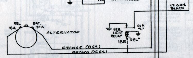
saw this on the internet on a 7060... THey have a RELAY in the green wire / brown wire that cuts IN and OUT depending on where the power is coming from...it appears the LIGHT is GROUNDED thru the RELAY and not the Alternator #1 terminal..
Possibly your RELAY is burn out, or has by bypassed ??
Either way, your in good shape now !
Edited by steve(ill) - 28 Sep 2023 at 8:49am
|
|
Like them all, but love the "B"s.
|
|
CrestonM
Orange Level
Joined: 08 Sep 2014
Location: Oklahoma
Points: 8388
|
Post Options
Thanks(0)
Quote Reply
Posted: 28 Sep 2023 at 8:47am |
|
Thanks Steve, your diagram makes sense, and with the extra brown power wire removed, it works as it should. I will look at the book again and try to figure out why that brown wire is there.
|
|
CrestonM
Orange Level
Joined: 08 Sep 2014
Location: Oklahoma
Points: 8388
|
Post Options
Thanks(0)
Quote Reply
Posted: 28 Sep 2023 at 8:48am |
steve(ill) wrote:
saw this on the internet on a 7060... THey have a RELAY in the green wire / brown wire that cuts IN and OUT depending on where the power is coming from...
Possibly your RELAY is burn out, or has by bypassed ??
Either way, your in good shape now !
|
I’ll upload a photo from my book, because it has different Alternator options. That one you posted might be the Niehoff alternator some of them had?
|
|
steve(ill)
Orange Level Access
Joined: 11 Sep 2009
Location: illinois
Points: 80181
|
Post Options
Thanks(0)
Quote Reply
Posted: 28 Sep 2023 at 8:51am |
|
YEA... i dont know that much about this specific tractor... Just a thought what the BROWN wire might be doing attached to the GREEN wire.
|
|
Like them all, but love the "B"s.
|
|
Lynn Marshall
Orange Level Access
Joined: 13 Sep 2009
Location: Dana, Iowa
Points: 2257
|
Post Options
Thanks(0)
Quote Reply
Posted: 28 Sep 2023 at 8:55am |
|
Those last schematics with the relay are for the early style neihoff.
Edited by Lynn Marshall - 28 Sep 2023 at 8:56am
|
|