| Author |
 Topic Search Topic Search  Topic Options Topic Options
|
dfwallis 
Orange Level

Joined: 09 Mar 2023
Location: Texas / Indiana
Points: 1052
|
 Post Options Post Options
 Thanks(0) Thanks(0)
 Quote Quote  Reply Reply
 Posted: 26 Oct 2025 at 3:08pm Posted: 26 Oct 2025 at 3:08pm |
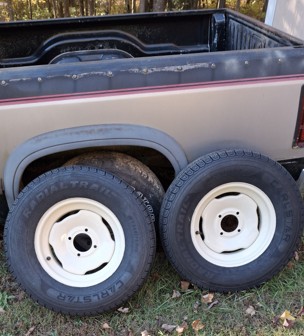
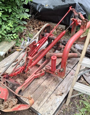
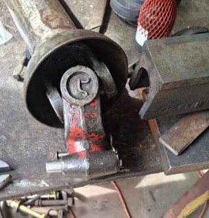
10/26/2025 Status (7): The Dunham Lehr disc rims were not in good shape. One of them was completely mangled. Can't even imagine how it could get twisted that way (or the tongue crank handle). The other one could possibly be salvaged with a week's worth of work. I opted to order some new rims and had Pomp's put some trailer tires on them. This increased the disc value by 500% or more  The better one had a G78-15 tire on it which would have been sometime in the 1970s.
Edited by dfwallis - 26 Oct 2025 at 3:32pm
|
|
1952 CA13092, CA Pickup Plow, CA Cultivator, CA Two Row Planter, Dunham-Lehr GC78 Disc, Grader Blade, 3pt Fm180 Finish Mower
|
 |
|
Sponsored Links
|
|
|
dfwallis
Orange Level
Joined: 09 Mar 2023
Location: Texas / Indiana
Points: 1052
|
Post Options
Thanks(0)
Quote Reply
Posted: 26 Oct 2025 at 3:19pm |
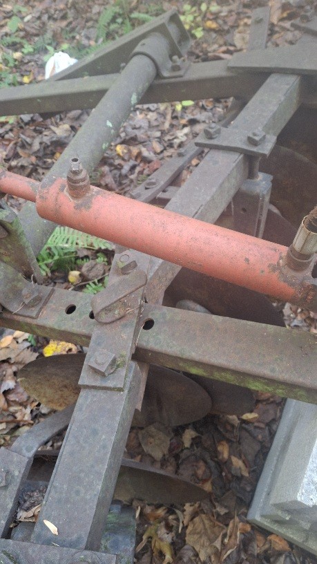
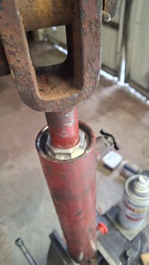
10/26/2025 Status (8): The last item was to remove and start cleaning up the disc hydraulic cylinder. If anyone knows what brand this would be, please let me know. AI says they owned a company called "versahaul" which made the cylinders, but I didn't find any parts for those. The closest appearing end cap/gland/head I saw was for a bradco. There is some minor pitting in the barrel and on the rod, but the rubber O rings all look like new. There was only a very tiny amount of water that came out of the petcock. I ordered a new 10' hydraulic hose for it. The old one was 9'4" and consisted of two jointed sections, one 1/2" and one closest to the tractor 3/8" but with 1/2" NPT fittings. I'll probably buy a breather plug for it after I decide what I need. Hopefully the hydraulic shop will be able to identify it (but I have my doubts). In any case, they said they could likely get it going. The gland is broken at the very end where the retaining rings hold it in place. The inner retaining ring will be fine, but the outer one wouldn't really fit against anything. It isn't really clear that the inner ring isn't sufficient, though. I ran out of time to inspect this further. The gland is aluminum. It looks like it would be easy for a machine shop to duplicate or perhaps create a separate clip piece that can be attached.
Edited by dfwallis - 26 Oct 2025 at 4:09pm
|
|
1952 CA13092, CA Pickup Plow, CA Cultivator, CA Two Row Planter, Dunham-Lehr GC78 Disc, Grader Blade, 3pt Fm180 Finish Mower
|
|
dfwallis
Orange Level
Joined: 09 Mar 2023
Location: Texas / Indiana
Points: 1052
|
Post Options
Thanks(0)
Quote Reply
Posted: 26 Oct 2025 at 3:56pm |
10/26/2025 Status (9): I checked the second wiring loop into the barn to see if it was live and it appears to not be live. If I had run both legs of the 220 to the barn, then I could use one circuit for the compressor and the other for my sandblast cabinet vacuum (insufficient current on the 1 circuit to run both). I would have to dig up the pump house cover to figure out what the issue is. I think there was a fuse box in the pump house, but can't quite remember for sure. I wonder how many timber rattlers are in there 
|
|
1952 CA13092, CA Pickup Plow, CA Cultivator, CA Two Row Planter, Dunham-Lehr GC78 Disc, Grader Blade, 3pt Fm180 Finish Mower
|
|
dfwallis
Orange Level
Joined: 09 Mar 2023
Location: Texas / Indiana
Points: 1052
|
Post Options
Thanks(0)
Quote Reply
Posted: 04 Dec 2025 at 2:24pm |
12/04/2025 Status:
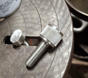
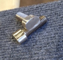
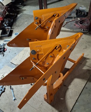
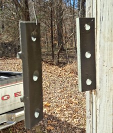
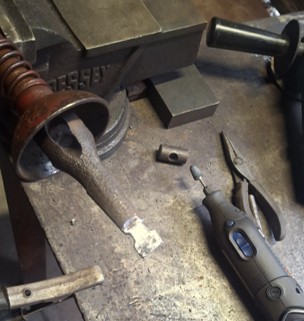
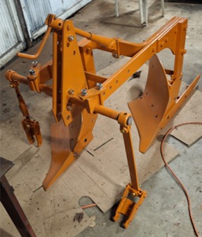
In order to complete assembling the plow, I needed two "locking" bolts that I didn't have. Dr P was sending me some, but had not received them (they may have arrived later after I left). So I made some out of stainless steel. I used some nice 1/2" "thumb" screws from McMaster-Carr. Chopped off the sides and top and hand ground to the right curvature. They actually fit the slots "better" than the originals. They are just a little long, but could shorten if it was needed.
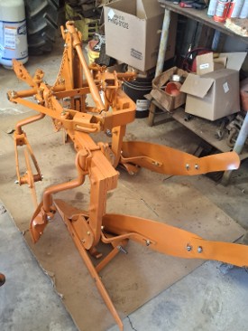
I'm not quite happy with the way the plowshare attaches. The spacer section on one is not meeting correctly because I didn't get the bracket bent back quite right. I'll need to work on that a bit more.
I was hoping to get further along, but it was a bit chilly and I had motivation problems...:( I also had to wait for some parts. I originally intended to use stainless in strategic areas, but some of the bolts I bought were of such low quality, that they kept galling with only enough force to close the lock washer. I quashed that and got grade 8 bolts instead. Actually had to cut one off that hadn't even been tightened enough to keep the parts from sliding around. After I cut it off, I tried getting the nut off and could not putting it in a vice and using a 24 inch pipe wrench. It was firmly welded in place :(
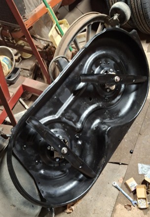
It was leaf mulching time, but all of the mowers were broken. It was about to rain, so I tried to get one of the riders going. I replaced the two deck spindles (which were probably used on another one), sharpened the blades, cleaned, and painted. I also straightened the deck wheel brackets. I moved to the engine itself, replaced the battery and got it started, but the float was sticking and dumping a huge amount of gas into the cylinder. I cleaned the carburetor but all of the rubber gaskets were deteriorated. So I ordered a new carburetor for about the same price as a gasket set. It didn't arrive until the last day of the trip when I was trying to get things cleaned up to leave.
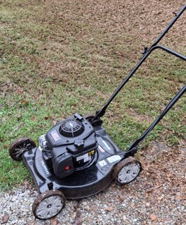
Since it was clear I wasn't going to get the rider fixed, I went to town and bought the lowest end push mower they had and mulched the main areas. It was very wet and things didn't mulch well.
I also took some of the Dunham Lehr disc tongue and rear gang mounts to the welder to be straightened up. He straightened the tongue brackets pretty well, but was unable to straighten the angle iron sections. Couldn't get enough heat on them. I opted to have him make some replacements I'll pick up in a few weeks.
I took the hydraulic cylinder to a shop for repair. He seemed optimistic about being able to repair it (even optimistic about locating a replacement head/cap section). He can also make one if needed. It's a pretty simple design in aluminum. Hopefully, that will be ready also to be picked up in a few weeks.
I put primer on various parts so they don't rust before I get around to painting them (including the above straightened brackets).
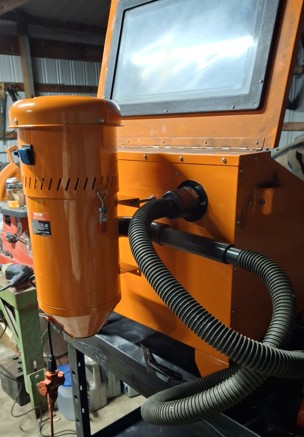
Edit: I also built a mounting system to add a vac onto the sand blast cabinet. This is the unit sold for the larger (vevor) blast cabinet. Was pretty easy to adapt. I liked it better than the small/puny one sold for this cabinet. I still can't operate it at the same time as the compressor though (inadequate supply current). I'll either have to run a long drop cord or work on getting the other leg of the 220 from the pump house to the barn. It's already probably wired, but does not seem to be energized at the pump house, which I'd have to dig up.
Edit 2: I designed some movement limiting bars for the hydraulic rams so that it's easier to use the single remote while leaving the 3pt mod in place.
Edited by dfwallis - 06 Dec 2025 at 2:27pm
|
|
1952 CA13092, CA Pickup Plow, CA Cultivator, CA Two Row Planter, Dunham-Lehr GC78 Disc, Grader Blade, 3pt Fm180 Finish Mower
|
|
Sugarmaker
Orange Level
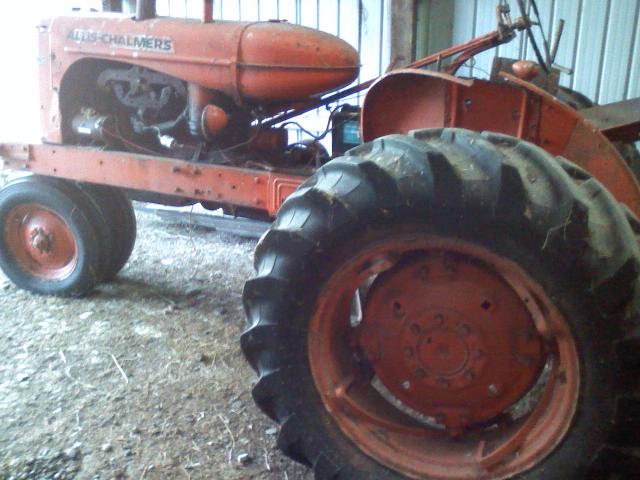
Joined: 12 Jul 2013
Location: Albion PA
Points: 8689
|
Post Options
Thanks(1)
Quote Reply
Posted: 05 Dec 2025 at 8:35pm |
dfwallis, You are always busy with projects! Your blast vac is similar to the one I added to my old blaster. It helps a lot. The other thing is that I added a very bright portable light inside the cabinet also. Your plow project is coming along nicely! Regards, Chris and Cheryl
|
|
D17 1958 (NFE), WD45 1954 (NFE), WD 1952 (NFE), WD 1950 (WFE), Allis F-40 forklift, Allis CA, Allis D14, Ford Jubilee, Many IH Cub Cadets, 32 Ford Dump, 65 Comet, 66 F100.
|
|
dfwallis
Orange Level
Joined: 09 Mar 2023
Location: Texas / Indiana
Points: 1052
|
Post Options
Thanks(0)
Quote Reply
Posted: 05 Dec 2025 at 9:02pm |
 Sugarmaker wrote: Sugarmaker wrote:
dfwallis,You are always busy with projects! Your blast vac is similar to the one I added to my old blaster. It helps a lot. The other thing is that I added a very bright portable light inside the cabinet also. Your plow project is coming along nicely! Regards, Chris and Cheryl |
I'll probably have to improve the lighting. I'll know better once I test the vac operation.
|
|
1952 CA13092, CA Pickup Plow, CA Cultivator, CA Two Row Planter, Dunham-Lehr GC78 Disc, Grader Blade, 3pt Fm180 Finish Mower
|
|
dfwallis
Orange Level
Joined: 09 Mar 2023
Location: Texas / Indiana
Points: 1052
|
Post Options
Thanks(0)
Quote Reply
Posted: 01 Jan 2026 at 12:19pm |
01/01/2026 Status:
The December/Christmas trip was less productive than planned relative to tractor/plow/disc progress. I did get new rear gang mounts made for the disc but didn't get them painted. I also checked on the disc hydraulic cylinder progress, but the guy that makes the replacement parts for them is out for 6-8 weeks with back issues. I could have taken it to one of the regular machine shops, but that would be several hundred dollars more and I can wait.
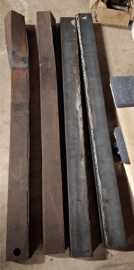
I spent several days getting one of the 4 broken riding mowers going. It seems to be working fairly well but the governor is not working correctly. It keeps trying to rev to max RPMs. I had to add an extra spring to bring it back to idle but the one I chose isn't quite strong enough. But I am able to control it over a very short range. Needless to say it doesn't "govern" properly, but at 16HP, it doesn't bog down that much anyway. I ordered a mulching kit for it. I installed the new carburetor and I had to straighten the front steering linkage crossbar, the deck, and the deck belt engage return spring bracket/rod. I tried adjusting the governor but there's very little adjustment to be made. Adjusting it to the "correct" setting per the manual leaves it revving. I could perhaps force it to limit the revving travel, but then it wouldn't have enough travel to perform the governing function (adjusting under load). More investigation when it warms up. It was annoyingly cold most days.
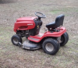
The other activities included fixing the left side garage door spring so my sister could raise the door (left cable frayed), and began work on the barn roof. It's starting to leak, several rust spots, and the drip edge is frayed from rust. As a deterioration delaying tactic, I started pop riveting a flashing strip over a spray on rubber coating. This is partly to protect the rubber coating and to provide the to-be-applied top rubber coating something to stick to underneath. That will probably consume the next trip as well. I ordered a new 12 foot ladder so I can climb on the roof.
Edited by dfwallis - 01 Jan 2026 at 4:56pm
|
|
1952 CA13092, CA Pickup Plow, CA Cultivator, CA Two Row Planter, Dunham-Lehr GC78 Disc, Grader Blade, 3pt Fm180 Finish Mower
|
|
dfwallis
Orange Level
Joined: 09 Mar 2023
Location: Texas / Indiana
Points: 1052
|
Post Options
Thanks(0)
Quote Reply
Posted: 31 Mar 2026 at 10:49am |
03/31/2026 Status:
I had medical, insurance, and tax issues to deal with so didn't get much done in January and February. In March, most of the work was focused on getting the barn roof ready for recoating. The eaves were severely rusted and on the verge of rusting into the interior. So I applied (kludge) flashing beneath the eaves with pop rivets and then a thick coating of sealant on top. The flashing was primarily to give the sealant something to stick to. I think it will extend the life for a few more years before new tin is required, as long as the coating is maintained. New coating may get applied in April (weather permitting).
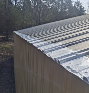
I was able to return to assembling the plow and now have it mostly complete. I had to make some plow bolts. I can find #7 head plow bolts online, but nothing smaller than 5/8" (need 3/8"). Dave the Plowman sent some but only partially covered the moldboard assembly. I found the closest currently available plow bolts and ground them to fit. They fit very well, about as well as the originals. I ran out of grade 8 3/8 bolts, washers, and nuts and didn't have time to go to town. They're on order and should be there before the next trip. This is primarily for the jointer clamps. I'm also missing the spacer that goes between the pull bar and the top through bolt of the U clamp. It looks like a U channel in the pickup plow manual (see other thread).
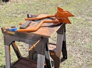
Aside from installing the jointer clamp bolts and the spacer for the pull bar (clip spacer?), the remaining tasks are to adjust the coulters and jointers, tighten up most of the bolts, and apply some touchup paint. Then I need to figure out where to store it, hopefully out of the weather.
Edit: I also started the tractor after it's 3 month winter break. It started easily and ran perfectly with almost no misses. It runs really well with the heavily modified TSX-670 carburetor. It did need slight choke for about the first 20 seconds (was 43 degrees).
I still haven't figured out what's wrong with the TSX-486. I assume something in the idle circuit. It's been "professionally" rebuilt and behaves the same as before (persistent misfires).
Edited by dfwallis - 31 Mar 2026 at 8:19pm
|
|
1952 CA13092, CA Pickup Plow, CA Cultivator, CA Two Row Planter, Dunham-Lehr GC78 Disc, Grader Blade, 3pt Fm180 Finish Mower
|
|
dfwallis
Orange Level
Joined: 09 Mar 2023
Location: Texas / Indiana
Points: 1052
|
Post Options
Thanks(0)
Quote Reply
Posted: 06 Apr 2026 at 11:31am |
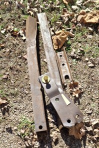
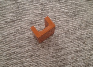
I wanted to make sure I have something ready for my next trip, so I made a draft (clip) spacer for the pickup plow pull bar. I'd still like to acquire the correct one, but this should work if I can't.
This is probably too thick to set the tongue at the right angle so I'll probably have to shave the bottom slightly. I don't think that's really critical though since you're never going to have a plow and tractor on perfectly level ground in the real world. If it works as-is, I'll probably not modify it. If I have to modify it, I'll consider cutting the sides at the same time to match the snap coupler rendering rather than the pin hitch rendering in the plow manual. What is the purpose of the side cutouts? Perhaps better moisture drainage? Better greasing access? Change for change sake?
|
|
1952 CA13092, CA Pickup Plow, CA Cultivator, CA Two Row Planter, Dunham-Lehr GC78 Disc, Grader Blade, 3pt Fm180 Finish Mower
|
|
dfwallis
Orange Level
Joined: 09 Mar 2023
Location: Texas / Indiana
Points: 1052
|
Post Options
Thanks(0)
Quote Reply
Posted: 11 Apr 2026 at 12:40pm |
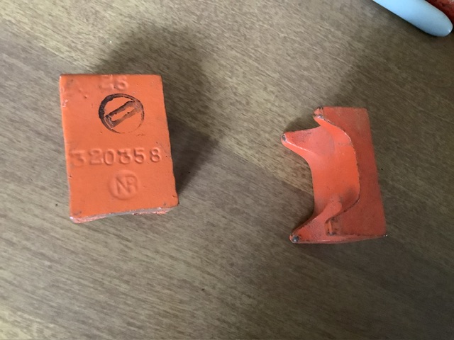
Here is what the plow pullbar (clip) spacer 320358 looks like. So, either the line drawing in the plow manual was inaccurate or they changed the design at some point without changing the part number. Since I couldn't find an image of it anywhere online, this is a good place for it (although I think older images get deleted from the site, from looking at very old posts).
Image courtesy of Mikez:
|
|
1952 CA13092, CA Pickup Plow, CA Cultivator, CA Two Row Planter, Dunham-Lehr GC78 Disc, Grader Blade, 3pt Fm180 Finish Mower
|
|
dfwallis
Orange Level
Joined: 09 Mar 2023
Location: Texas / Indiana
Points: 1052
|
Post Options
Thanks(1)
Quote Reply
Posted: 26 Apr 2026 at 10:47am |
04/26/2026 Status:
As for the March trip, the April trip was largely consumed by barn roof repair and some yard/tree work. The roof was pressure washed and the first coat of primer applied. The second coat of primer is expected today and the white insulating seal coating in the coming weekends (2 coats) (brother/nephew). The 1 coat of primer alone seems to have stopped all but one leak.
I also ordered 5 ton of gravel and spread about half of it in front of the barn doors. The 4 inch lip is a little hard to get things in and out (like lawn mowers). I'll spread the rest next trip (unless somebody else gets to it first :).
My brother pulled several stumps from the front yard. He was leaving a giant gash in the yard so we decided to try the CA rear forks. It worked reasonably well on the smaller one. Was able to lift it up about a little less than a foot (lots of mud on the root ball) and mostly carry it up to a wood pile. The larger one was another matter. It was so heavy that attempting to lift it was raising the front wheels off the ground and making it very difficult to steer. I already had two front wheel weights (~200lbs). I tried adding two 70lb weights to the side weight cradles but not enough. Another two 70lb weights and I was barely able lift it enough to at least not dig a long trench and mostly dragged it to an area adjacent to the wood pile. I couldn't back up because the forks were digging into the ground.
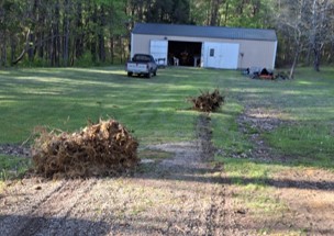
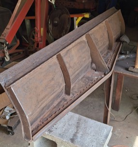
I began cleaning up what I believe was once a CA pin hitch compatible grader blade. It appears to have needed significant work and I believe dad added support bracing and a manganese blade on the front. Most of the welds were broken however so I decided to remove it and purchase a king kutter reversible bolt on blade. Hopefully I can adapt it. I began wire brushing, grinding, and sand blasting and got it clean enough to decide on a plan for improvements.
It was not originally machined for the ability to angle the blade. Those existing pilot holes were never drilled. So I drilled them and then had to grind away some of the reinforcement (t post) structure so that you could access the bolts/heads. It may need additional holes. My measurements indicate that the existing holes only tilt about 15 deg. I think 30deg is probably required, but I'll probably mock it up and try it first.
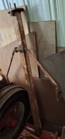
This is the original CA pin hitch compatible drawbar. Since I don't want to have to take the 3 point hitch off, I'm making a separate 3 point attachment for the grader. I'll clean this up also.
The turret cleaned up fairly nice. I'll explore sandwiching a UHMW (Ultra-high-molecular-weight polyethylene) sheet between the two plates. They tend to rust weld together.
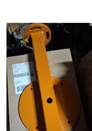
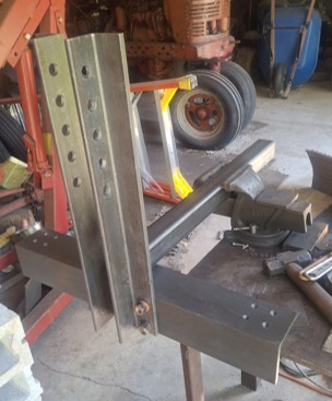
I started on the 3 point hitch adapter. I don't seem to have gotten a later picture. It is mostly completed, including top link side and rear bracing. The plate I ordered for the end of the square tubing that mounts to the turret arrived but was the wrong material (the listing said nothing about stainless steel, just "hot rolled"). So I had to reorder. I'll have to tack weld it on and test it until I decide how much to cut off of the rectangular tubing. The blade was really close to the lift arms in the pin hitch configuration and was not set up to be angled. I'll need it back far enough to accommodate potentially 45 deg at least (5 foot blade). I may explore an adjustable attachment for the turret so that I can bring the blade closer or further from the tractor. A sliding tube/bar within the square tubing would be easy.
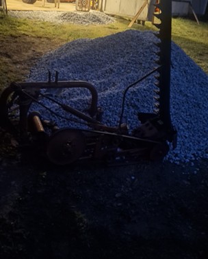
I bought a MF41 sickle mower for $250. The sickle portion seems in good shape, but some of the adjustment rods are in bad shape and unusable. The main lift rod that lifts the floating blade attachment point appears to have had welded on an additional several feet and has been bent around in a giant arc. I'm guessing bending it was an attempt to get the right side to lift but it's not working very well. Unsure why the extra length was added. It certainly doesn't need that much length to reach the attachment point (the blade raise/lower bracket on the left lift arm attachment point). I had to use a chain to get the right side to lift along with the left side so that I could put it on a pallet.
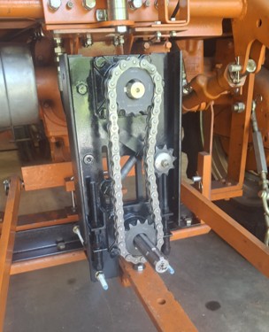
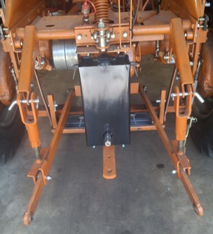
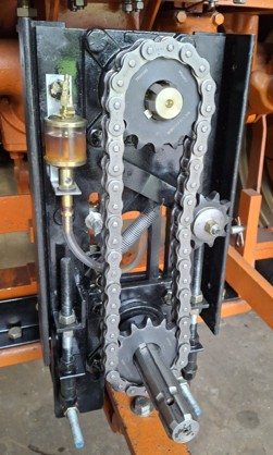
It was a pain to get it attached to the 3 point on the CA. Because of the blade lift attachment on the left side, the pin was too short for the lift arm to attach (hole covered). It turns out one side has a long pin and one side has an exactly cat 1 length pin. These were reversed side to side. So I reversed and put the longer pin on the left side and everything attaches now. Except the PTO shaft. The MF41 PTO shaft is only 10 inches from the ground. The CA PTO shaft is 30 inches from the ground. Needless to say, the PTO would have to go through the MF41 frame to attach. So...a new design project (will they ever end???). I've designed a chain/sprocket system to lower the CA PTO attachment to ~18 inches above the ground which is more common (and aligns with where I designed the 3 point lift arms. It will also have an extendable shaft. Because the CA drawbar is still attached, I'll a need little extra flexibility. This should dramatically improve all 3 pt operations.
Edit: The bracket will have an extra bearing on the reverse side to provide greater lateral/side thrust support for the extendable shaft.
Not a good picture below. I don't seem to have taken one. Too busy shoveling gravel (the gravel guy dumped it on the mower :( )
I installed a couple of $30 magnetic side mirrors on the CA. It is helpful, but they aren't quite adjustable enough (should have gotten a different brand for a tiny bit more).
Edit: I also adjusted the coulters and jointers on the plow. I had hoped to finish but after finding the missing clip spacer, I decided to clean up and install the original. But mostly I had other priorities for the trip.
Edited by dfwallis - 27 Apr 2026 at 3:15pm
|
|
1952 CA13092, CA Pickup Plow, CA Cultivator, CA Two Row Planter, Dunham-Lehr GC78 Disc, Grader Blade, 3pt Fm180 Finish Mower
|
|
dfwallis
Orange Level
Joined: 09 Mar 2023
Location: Texas / Indiana
Points: 1052
|
Post Options
Thanks(1)
Quote Reply
Posted: 31 May 2026 at 12:03pm |
05/31/2026 Status: I finished the CA pickup plow. Mostly inserting the clip spacer and tightening bolts and a little touch up paint. Still deciding on where I'm going to store all these refurbished items out of the weather. I'm considering a lean-to addition on the back of the barn or a new barn elsewhere.
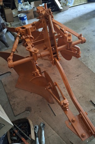
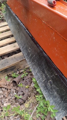
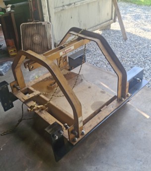
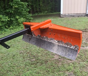
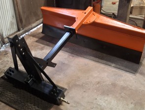
I finished up the grader blade modifications. It appears that this was 100% custom dad -designed to fit the CA. I designed a 3 point adapter for it (probably excessively sturdy and I've since found some off the shelf items that could have been more easily modified, but it was fun). I modified it further to get 15 and 30 degrees of rotation. It originally had no provisions for rotation (other than some undrilled pilot holes for 15deg). Here i've modified it to accept an off the shelf king kutter replaceable blade. It originally had a flat 2 inch manganese strip as the cutting edge, but the welds were mostly broken. Here I added a thick backing plate and drilled 5/8 inch mounting bolt holes for the KK blade. I'll need to seal the top edge of the reversible blade to stop dirt/rock accumulation. I'm not quite sure what would work best. Maybe some silicon would work ok for that (like permatex gasket material, not GE clear).
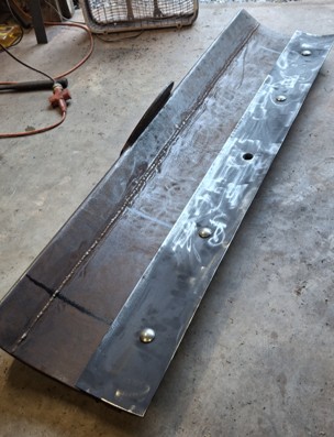
I used it to clean up the area where the stone was piled for the driveway into the barn. Those protruding support beams were in case I decided to relocate the attachment point further back. I wasn't sure whether I was going to shorten the length of the lift tube or not. It seems fine where it is, so I'll probably cut those off. This puts the blade at about 4.5 feet behind the tractor wheels. The original pin hitch adapter only has it about 2.5 feet behind the wheels. I also cleaned up the pin hitch adapter. Dad had made a new lift arm attachment design but never welded it on. I may do that at some point. He seemed interested in having me do that. It currently has some crude loops welded on so he could use it immediately. He envisioned another cross link bar of some sort I'll have to ask further about.
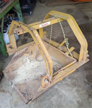
I purchased a KK dirt scoop for $220 off of marketplace. My first positive experience with fbmp. I used it also on the gravel pile to help move the final large loads to the driveway. Most of it was done with a shovel and wheelbarrow, before I got the dirt scoop and finished the grader blade :( Unfortunately there are a few issues with the CA attachment.
1) Since the top link bracket slides on the rock shaft, it doesn't provide good "pushing" stability. It does fairly well for pulling stability. But the bucket tends to want to rotate on the lower link arms. I'll have to create some anti-rotation brackets for the lower link arms. These will probably have to be adjustable so I can tailor the angle of downward tilt of the bucket to either dig in (slightly) or be perfectly level.
2) Also, the bucket sticks out nearly a foot in front of the lift arm connection points in the forward direction. Since the drawbar is still attached, I'll have to create an extension to mount the bucket further back so it can lift and miss the drawbar. It worked better in the reverse direction but it still needs some anti-rotation support. Since I see several areas where anti-rotation at the lower link connection point would be beneficial, I may try to make something generic for the lower lift arms, rather than something for each implement.
The main project was to finish up the PTO adapter. I worked this up mostly at home in TX then shipped the developmental version (which of course doubled the cost). I tried it out with the finish mower and it worked better than I anticipated (I expected broken chains and nuclear explosions or worse :( :) The only issue really was some of the set screws came loose (and the chain stretched). I thought sure I did a final check of them all. All of the loose ones were on the lower shaft. All of the upper shaft items were fine. I do have a vague memory of adjusting the lower shaft to gain clearance to get a wrench in behind, so maybe I just forgot to tighten everything back up :( I also bought some additional locking collars if this proves to be a problem (that locktite won't fix).
My original goal was to make this adjustable from 16 inches above ground to 20 inches above ground. However, my memory of the height of the drawbar was off by 1/2 inch so it ended up that about 17 inches above ground is as low as I could go (without modifications to remove the drawbar obstacle). The lower sprocket (4 inches) would likely be too close to the drawbar. So, it is set at 18 inches which was my normal operation goal and seems to work well there. I had made 3 sets of chains for 16, 18, and 20 inches. The actual adjustment range of the backing plate is 16.5 inches to 24.5 inches, but fitting in the sprockets and idler (and eventually an oiler system) limits the practical range of adjustment.
It has a quick disconnect PTO overrun clutch at the top. All of the original ones with the quick disconnect had much too short PTO shafts. They were only a little over 2.5 inches long. That's not long enough to extend through the backing plate, the bearing, and have enough left to mount the sprocket onto. So I had to purchase a separate PTO extender adapter that had an extra long PTO shaft to create an overrun clutch with the correct characteristics. I cut the original PTO clutch shaft at 5/8 inches, cut the PTO extender back end socket to 5/8 inches and then welded the new PTO shaft on. It appears to be running very true (a worry).
It has a chain tensioning system that consists of two fine threaded rods that pull down on the lower bearing flanges. These firmly prevent slippage. It might have been enough to tighten just the bearing flange bolts and eyeball the chain tension, but I prefer having this fine control over the tension adjustment. I think that the chain stretched more than anticipated on first use though. That's concerning, but will see if that continues after I re-adjust. I may need to remove a chain link to keep it at 18 inches above ground level.
Mounting stability at the bottom is through 2 threaded rods mounted to the drawbar bail.
Bottom end rotation prevention is mostly provided by a cutout in the bottom of the backing plate that allows it to slide below the top of the drawbar.
Since this device is very heavy, in order to try to lessen the weight load on the tractor PTO shaft, I created a downward facing set screw that presses on the top of the drawbar and raises the device just enough to reduce the weight on the PTO shaft. This is likely going to have to be adjusted periodically (has a locking nut but things will wear).
Edit: Background is that the CA PTO shaft is 30 inches above the ground. This causes an extremely sharp PTO shaft angle when operating most 3 point equipment in the down position. I didn't think it was practical to keep using it for 3 point implements without this solution (or a gear driven one, but that made it more difficult to define something adjustable). I just hope it's not too unreliable.
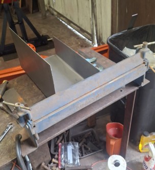
I created a guard for the PTO adapter. This is a homemade brake. It worked fairly well, but was just slightly understrength for 1/16 inch steel. The plate bows in the middle leaving nice crisp ends but fat curves in the middle. Good enough, though.
I removed and cleaned up all of the adjustment rods/mechanisms on the MF41 sickle mower. I didn't have time to hook it up and start adjustments though. I cleaned all the mud off of the bar and looked at the teeth. It's clear it could use a lot of new teeth. Most look fairly good, but a few have zero serrations. Otherwise, it seems to be in really good mechanical condition.
Edited by dfwallis - 31 May 2026 at 7:03pm
|
|
1952 CA13092, CA Pickup Plow, CA Cultivator, CA Two Row Planter, Dunham-Lehr GC78 Disc, Grader Blade, 3pt Fm180 Finish Mower
|
|
dfwallis
Orange Level
Joined: 09 Mar 2023
Location: Texas / Indiana
Points: 1052
|
Post Options
Thanks(0)
Quote Reply
Posted: 29 Jun 2026 at 2:06pm |
06/29/2026 Status: I added an oiler for the PTO adapter chain. It seems to work ok. I had some difficulty getting it to drip feed. I ended up having to put an open standpipe near the brush (back side). The brush touches the back side of the chain. Not ideal, but it's a bit longer than expected and was proving difficult to place. It seems to be getting oil where it needs to. I can supplement by brushing some gear oil on once in a while. I have to remember to turn the oiler off between uses, otherwise it drips all the oil onto the floor. I've ordered a small catch pan that I'll add next month. I'll probably attach it with magnets, atop the drawbar. I also added a collar type clamp around the bottom PTO shaft to reduce shaft movement in case the allen set screws come loose. I had one come loose again on the back side. I'll have to watch that until I figure out whether I'm just not getting them tight enough or whether it's going to be a continuing problem.
Because of chain stretch from first use, I had to remove 1 link from the chain to keep it at around 18" from the ground. It appears necessary to set the chain tension AFTER installed on the tractor because the top bearing flange does not support any side force at all. I'll see if I can find a more appropriate thrust bearing, but that may force me to do the same for the bottom one since the sprockets must align (depends). The bottom set has a bearing on the back side to support side forces. I can't do that on the top since it has to attach to the tractor PTO shaft.
Edit: I've researched alternative flange (roller) bearings and decided that I'm not going to spend $400 to $600 and then have to redesign the mounting point. The base problem is that these flanges are 'self aligning'. The bearing outer surface that's pressed into the flange housing is curved and designed on purpose to rotate in the housing. Absolutely not what I wanted, but I'm not finding any that aren't designed that way or that overtly say that they're not self aligning. I'll see if I can come up with a way to inhibit rotation.
I sealed the top of the grader blade with Sika silicone. I think this will work fine to keep dirt and rocks out. It's a pain to clean out otherwise. The King Kutter blade contour doesn't quite match dad's homemade housing.
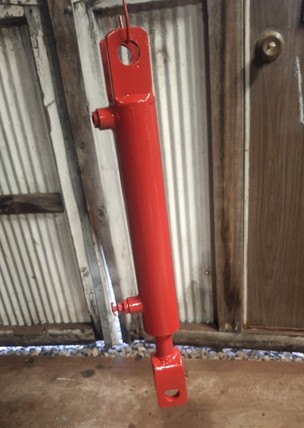
The Dunham Lehr disc cylinder was finally rebuilt. It took about 9 months. The machine shop guy was out for months with back problems then I think got behind. Anyway, I got a discount since it took so long. I think I only paid for the machine shop, not the actual rebuild and test. The machine shop created a new "head" part by copying the old one. The original did not have an octagon end, it was round with one flat side for access to the snap ring. I wasn't too happy with the internal cleaning. I had to remove quite a bit of gunk before I cleaned it up and painted.
Possibly the best looking 70+ year old Dunham Lehr hydraulic cylinder on the planet :) I thought it was originally "flambeau red", but after shining it up, it's more massey ferguson red, so that's what I used.
I made some adapters to position the KK dirt scoop further back to keep the scoop from hitting the drawbar, but my original solution had the lift points too low (scoop could not quite be lowered enough at the right angle) so I scrapped that design and began a new one to get the lift arms back up in line with the originals. Since both the front and the back end need "anti-rotation" protection (because the add-on top link slides on the rock shaft and doesn't support pushing), I'll do something similar on both the front and the back. The starting point is two long rails on either side that I can bolt the new brackets to when the material arrives. The back doesn't need to be very long so I'll size that as needed once the brackets are designed.
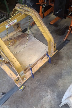
I previously created some substitute "bail pinning" bars that work similar to pinning the hydraulic arms to the pin hitch bail. I added two new "scissoring" bars that allow me to adjust how high the implement is lifted. It basically adjusts where the "end of throw" is. They may be slightly undersized but I don't generally leave the lever in the raise position, I get it to the right height then place it in the hold position. This will just make it easier to stop it at the right place (mainly for PTO implements where you don't want an extreme PTO shaft angle). I'm pretty sure they'll be fine when the high implement weight is already reducing the lifting force that will be applied to these bars.

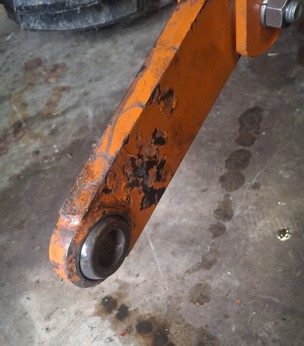
The left lift arm ball has been quite difficult to use because the ball is extremely tight. The right one limbered up well with a bit of oil, but the left one appears to have possibly gotten too hot when they welded it on and warped. I used a 2 foot bar to try to limber it up but wasn't helping much. I ended up trying an impact wrench on a 7/8 bolt to try to spin and tilt in all directions. That was difficult but eventually it improved and I found at least one small position of rotation where it is almost free enough to be usable. I'm wondering if I could add some polishing compound of some sort and spin it more with the impact wrench to try to free it up more.
I began experimenting with the MF41 sickle mower. Last month I cleaned/fixed all of the adjustment rods/brackets, but didn't have time to check anything out. It is clear that it's much improved. I can now lift it up without the bar attachment end flopping down to the ground.
I did identify one problem that had to be rectified before going any further. The MF41 has a device on the left side that hooks beneath the lift arm. Unfortunately, it hits exactly where the leveling arm attaches to the lift arm. I had left those attachments loose to allow easy side to side sway of the lift arms. However, the sway chains also attach at the same position and when sway force is applied, they can pull the bolt holding the leveling arms out and into the path of the MF41 lift attachment. So I had to modify how the sway chains are attached. I created new brackets to get the chains a little further back from the leveling arm attachment points and I used spacers to ensure that the bolt doesn't slide out under sway chain force. I also smoothed a ledge on the MF41 where the bolt was hitting so that it now smoothly slides past. The MF41 lift attachment is fairly loose fitting and can easily be pulled outward enough to miss but doesn't naturally do so. I would have preferred a 135 deg strut rather than 90 deg, but this will work fine. I'm waiting on some 3/4 inch eye bolts to attach the sway chain to. This bracket tended to rotate downward when the sway chain was loose so I added a little clip that hangs over the lift arm to keep it from falling down and into the path of the MF41 lift attachment. Hopefully, it doesn't get ripped off in operation, but I think it should work. The sway chains are almost always higher than this bracket so I don't think anything will pull downward on it.
Edited by dfwallis - 30 Jun 2026 at 1:43pm
|
|
1952 CA13092, CA Pickup Plow, CA Cultivator, CA Two Row Planter, Dunham-Lehr GC78 Disc, Grader Blade, 3pt Fm180 Finish Mower
|
|
dfwallis
Orange Level
Joined: 09 Mar 2023
Location: Texas / Indiana
Points: 1052
|
Post Options
Thanks(1)
Quote Reply
Posted: 03 Aug 2026 at 3:14pm |
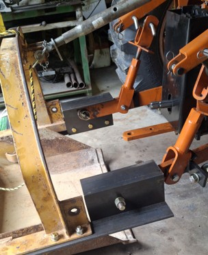
08/03/2026 Status: I completed mods to the dirt scoop. Because the front end of the scoop sticks out so far, it would hit the drawbar when raised. So I added some extensions to move the mounting points out about 6 inches. That reduces the lift capacity, but there was no way to use it as-is. The 3 point adaptor utilizes the existing drawbar. For the reverse connection, because the top link bracket on the CA rockshaft doesn't provide any pushing support, I used angle brackets to limit the rotation at the lower lift arm connections. I've since modified the top link bracket with a separate locking mechanism, but a little extra protection doesn't hurt.
After the picture below was taken, I moved the lift point out another two inches. Depending on the angle adjustment of the top link, the bucket could still hit the drawbar (barely).
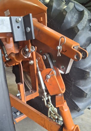
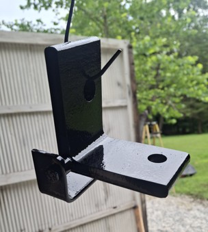
Below is a pic of the top link bracket as it comes and shows that it provides no pushing (rotational) support except straight on with the rockshaft (which seldom happens). If the top link is a little out of straight-on alignment, it tends to rotate upward (it's blocked from downward rotation by the PTO guard), which can cause the implement to rotate on the lower lift arms and can cause the top link itself to rotate downward smacking into the PTO shaft (in my case the PTO adapter). I chose this wide one because I thought I could make a clamp to apply enough clamping force to stop the rotation, but it didn't stand a chance against a dirt scoop being pushed into a pile of rocks/dirt. Of course, it might rotate less if I had left the top link connection vertical instead of horizontal, but depends on which top link you use and how much flexibility it has. The bracket is actually made for a larger rockshaft than the CA, so the aft bolt that should stop the bracket moving backward still leaves a lot of room for the bracket to move backward and smash the CA platform edge. So, it needs something behind the bolt and in front of the rockshaft to limit it's backward motion. That's partly what my clamp system did.
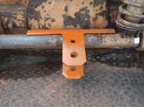
Because I didn't want to weld or drill the rockshaft, I used a 2.75 inch flat all across the rockshaft with angle brackets to lock it in position with the CA lift arms. This worked very well. It would not work so well without my modification to turn the top link mounting point horizontal instead of vertical as the bracket comes. So as the implement goes up, this also goes up (but not necessarily at the same rate). In practice, it worked perfectly (at least as tested).
The paint wasn't dry on my last day, so I didn't get them re-installed. If I were to do it over, I'd probably have gotten a 3 inch wide flat and cut a deeper slot in the bottom edge to further protect against the bracket sliding sideways. In practice that's unlikely and I was able to reuse the outer clamping plate of my original clamp design. It was necessary to include a notch on the top edge to clear the hydraulic lever guide.
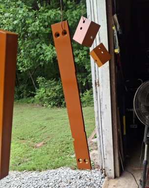
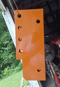
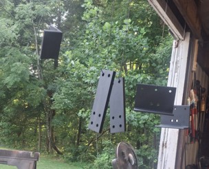
In order to improve control over how high the lift arms travel, I have two solutions: 1) a pair of scissor bars that unfold to stop further upward travel, and 2) a new method of attaching the leveling arms. This is a 5" x 12" x 1" flat that slides up inside the CA lift arms. Along the bottom edge are 4 holes. The outermost lift point at the end of the CA lift arm has a 26" lift range. The first hole in the attachment plate has a 24" lift range, hole 2 is 21", hole 3 is 16.75", and hole 4 is 13". This of course assumes it's able to lift the load at those positions. In testing, it lifts the ~600 lb finish mower at the 3rd hole fine, so I don't anticipate any operational issues.
The cutout is to clear the hydraulic cylinder. All holes are 5/8"
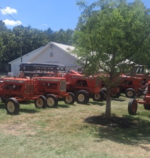
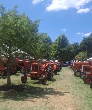
I had a short visit to the Jackson County fair and walked through the tractor exhibits. This year's feature was AC. I think unstyled WC was the oldest example I came across. I cut it short because I was late for a class reunion gathering. There were two CAs. The closer I look at many "restorations", the better I feel about mine :) The only thing is their paint is shinier than mine, but mine is more authentic (e.g. closer to the correct color).
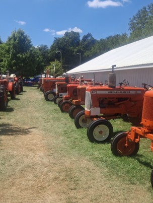
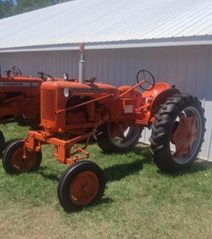
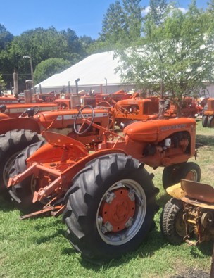
I spent some time mowing the field behind the barn again, partly to test the new leveling arm attachment and top link bracket rotation position lock. And again, the set screws on the PTO adapter came loose. I went over them all with loctite. We'll see if that is the solution. I added the rear collar clamp to further stop the PTO shaft from moving in/out. I previously installed the front one because that's the more dangerous one that could cause the PTO shaft to separate. That isn't actually likely because the shaft lock would have to fail and its length is close to the minimum possible that you can still connect the shaft.
Unfortunately, the overrun clutch stopped overrunning. Either the welder got it too hot, or the side stress caused by the chain is too great. I'll have to investigate that next trip. :(
I glued some additional float material on the 10 inch bayonet style fuel cap/gauge. It worked fairly well, showing reasonably accurate 1/2 full tank. Unfortunately, the recommended 3M epoxy was not liking the gasohol environment so I applied some better epoxy. I also purchased another 11.5 inch cap/gauge (for cheap) and may consider merging the two. They stopped making the bayonet style in 2019 :(
Other things accomplished: repaired a fan tripod, cleared 3 gallons of water out of the Chrysler 300 floorboard and tarped it. Some drain somewhere is blocked. I could not locate it.
Edited by dfwallis - 03 Aug 2026 at 6:38pm
|
|
1952 CA13092, CA Pickup Plow, CA Cultivator, CA Two Row Planter, Dunham-Lehr GC78 Disc, Grader Blade, 3pt Fm180 Finish Mower
|
|
dfwallis
Orange Level
Joined: 09 Mar 2023
Location: Texas / Indiana
Points: 1052
|
Post Options
Thanks(0)
Quote Reply
Posted: 12 Aug 2026 at 8:47pm |
2026 Jackson County Indiana Fair Allis Chalmers Featured Tractor Review:
https://www.youtube.com/watch?v=ix69WPUUfkY&pp=ugUEEgJlbg%3D%3D
Edited by dfwallis - 12 Aug 2026 at 8:48pm
|
|
1952 CA13092, CA Pickup Plow, CA Cultivator, CA Two Row Planter, Dunham-Lehr GC78 Disc, Grader Blade, 3pt Fm180 Finish Mower
|
|
Dan Hauter
Orange Level

Joined: 06 Feb 2011
Location: Carlinville, IL
Points: 1287
|
Post Options
Thanks(0)
Quote Reply
Posted: 13 Aug 2026 at 3:31pm |
|
I helped a friend rescue some Hudson cars that had been where they were for far too long. Required chain saws. shovels, jacks, wrenches, spare tires, air compressor, etc. And a tractor to pull them out once we got them free. Then winched them onto a truck. Big fun!
|
|
dfwallis
Orange Level
Joined: 09 Mar 2023
Location: Texas / Indiana
Points: 1052
|
Post Options
Thanks(0)
Quote Reply
Posted: 02 Sep 2026 at 12:58pm |
09/02/2026 Status:
1) I was not as productive relative to AC stuff this trip. I made some mods to the sway chain attachments to further displace the connection point behind the MF41 mower blade lift mechanism (which hits right where the leveling arms attach). It only needed it on one side, but I made the mods to both sides because it also helps with the connection of the leveling arms to the new CA lift arm attachment plate. I also bought some 5/8 "eye nuts" to use in place of the hex nuts on the leveling arm lower attachment point. For some implements, that would be a better attachment point for the sway chains. I like having options. But that method doesn't work with the MF41.
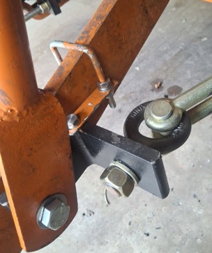
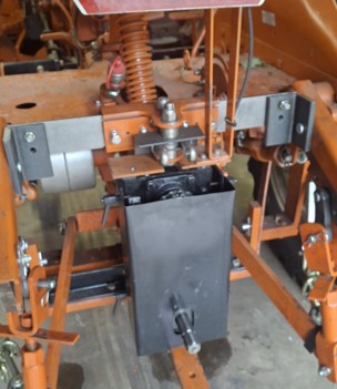
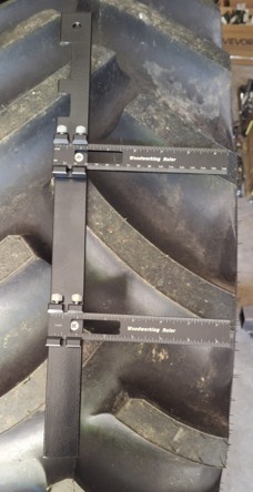
2) For mounting my PTO chain drive adapter, I needed a guide to help me mount it true, to minimize side force (and weight) on the CA PTO shaft and the overrunning clutch attachment. The below guide slides into the stock PTO guard and has extendable rulers to help me get the alignment right. I clamp it in place to the PTO guard side braces. The cutouts are to avoid bolt heads and welds.
In another post, I had mentioned difficulty with the overrunning clutch not releasing with even light hand pressure. With this guide I was able to accurately adjust the attachment to allow the clutch to operate correctly. The vertical weight adjustment of the attachment is also required of course. I may have to beef that weight adjustment up some. It is a single 1/2" bolt that presses down on the top of the drawbar. But after mowing 3 acres it seemed to still be properly adjusted (the OR clutch was still releasing). The attachment is slowly becoming more reliable as I work through the issues. I'm pretty sure I'll have to continue to check alignment before every use though.
3) I installed the new, newly painted, 3 point lift brackets. After mowing several small fields, the PTO chain drive adapter seemed to be working very well. The set screws did not appear to have come loose. That would be very obvious, but I checked before moving to the second field and all was well so I continued on. It appears that the best leveling arm connection position for the finish mower and the MF41 will be the position closest to the cylinders which gives a lift range of 13 inches. At that point, it is virtually impossible to cause the PTO shaft angle to become too great. That's exactly what I was hoping for. I don't like having to worry about lifting the mowers too high. The new mods also allow me to make proper top link tilt angle adjustments (level, tilted back, or tilted forward). It was more difficult when the lift range was too great. And it has the effect now of lowering the rear of the mower when down (allowing it to float with the terrain better), but leveling it when lifted so it doesn't droop. I damaged one of the wheels (tread) on the mower because it was drooping too much one time. There was no evidence of lack of lift force from connecting the leveling arms at the sharper angle towards the hydraulic cylinders.
4) I had an opportunity to fit check the mods made for the MF41 mower. I believe they'll work well. I have not yet made a PTO shaft to fit. The OEM MF shaft seems to be already cut to its shortest length (a plastic slide/guide at the end would have to be removed to shorten it). So I ordered an adapter to mod the MF41 to a quick release PTO shaft on both ends and I'll get a new one that i can mod to the correct length. I've still not made the adjustments for the blade lift mechanism. I did clean up/undented the OEM PTO shaft and ordered a new quick disconnect lock. The old one was so completely rusted and bent I could not break it lose with a sledge hammer. I had to drill it out (9/16 bit). I'm not sure how I got the center punch so perfectly aligned but there's virtually no damage to the original hole :) I've not painted the old shaft yet. I probably will anyway, but don't anticipate using it directly since I can't shorten it further without messing up the safety shield slide mechanism.
5) Spent some time installing a slide bolt on the east barn doors to force the top of the warped doors to close. I made one for each side a few trips ago, but the west barn doors seem to have unwarped recently.
6) Analyzed the failure of the Murray riding mower. I was aware that the plastic governor gear was likely broken which was causing the engine to rev excessively. I installed a heavy spring that helped me control the speed but when you disengage the blades, you had to adjust quickly to keep it from revving. Just as I turned it off in June after mowing, I heard something shatter in the engine. Very crunchy. I disassembled the engine and found that the counterweight mass is separate from the crank and one of the connecting arms made out of pot metal had shattered. And the cheap plastic governor gear was broken. Rather than continue to waste my time trying to get one of the 4 broken/mangled mowers going, I decided to just get a new one and try to scrap the others. I could fix them all, but that would consume my entire trips and I have other things I'd rather work on. I really don't like that B&S engine design. Designed to fail.
7) Worked on diagnosing the Chrysler 300 rain water leak into the interior. Cleaned/vacuumed all of the likely areas, but wasn't clear anything was actually clogged (e.g. sunroof drains in each corner are clear, around wiper blades, windows, air filter compartment on passenger side). Anyway, I'll continue tarping it for now. Also aired up tires in all vehicles but the truck is going to have to have some tire work to get them to seal (massive leak all the way around on the left front in addition to all leaking around the valve stem base).
8) Installed overrunning clutch on the M for the brush hog and attempted to desulfonate a few batteries (one successful one not).
9) Bought and assembled a rolling parts cart with 90+ trays to put my nuts and bolts in. Got tired of the plastic bags and buckets and spreading things on the floor/bench.
10) Buried the 19.5 year old kitty (Callie). 
Edited by dfwallis - 04 Sep 2026 at 8:43pm
|
|
1952 CA13092, CA Pickup Plow, CA Cultivator, CA Two Row Planter, Dunham-Lehr GC78 Disc, Grader Blade, 3pt Fm180 Finish Mower
|
|
dfwallis
Orange Level
Joined: 09 Mar 2023
Location: Texas / Indiana
Points: 1052
|
Post Options
Thanks(0)
Quote Reply
Posted: 28 Sep 2026 at 1:26pm |
09/28/2026 Status: 1) Again only minor CA activity this trip. The majority of the activity was getting implements and property/landscape areas ready for CA use. I plan to raise numerous tree canopies and clear some trails through the woods so that I can drive the CA to the far fields without knocking the lights, mirrors, and canopy off and scraping the paint off.
I did replace the paper fuel filter with a free flowing mesh filter. I believe one of the issues was the paper filter not working so well with a gravity feed delivery system that is almost horizontal from the tank. I also increased the size of the vent hole in the fuel gauge cap. The cap comes unvented but the one I originally drilled was too small. Then I had to re-adjust the carburetor. It was running a little better but that random miss issue has returned (with a TSX670 carb, not the original TSX486). It does not happen at idle or when under load.
I also added loctite to two more set screws on the PTO chain drive adaptor. I guess I missed two. It still seems to be adjusted correctly and the overrun clutch is still functioning correctly.
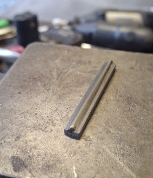
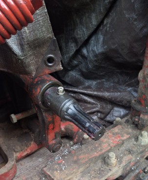
2) I modified the MF41 PTO connection from spline to quick disconnect. I had to make a custom key to mesh with the 19-spline shaft. Technically, it wasn't necessary because I also drilled a matching through hole for a 5/16 bolt.
3) I installed the new lock in the OEM PTO shaft. It will be unused since I couldn't shorten it without damaging the shield slide mechanism. I purchased a new PTO shaft to connect to the CA. It looks like it fits perfectly as-is (no cutting). How often does that happen???
4) The H has been dead for several years. Dad thought the gears were stripped. However, I found at least part of the problem was worn shift linkage. It was almost straight on the end. I welded some new sections to try to approximate new dimensions (3/4"). I also ordered a new retaining pin. The original has press fit caps to hold the pin in but I elected to get the new fangled one with the screw on one end. Of course it didn't fit and had to be modified, but was just grinding the heads down to fit the recess. The caps were missing and someone had added two loose nuts and a band clamp to hold the pin in but the band clamp was slipping around and interfering with the movement of the shift lever. All better now.
Gears now seem to shift correctly. We may try to resurrect the engine next trip and see what else might be wrong with the gears. I'm pretty sure the PTO shaft is about 1/2 stripped. It turns free about 180 degrees then appears to engage gears.
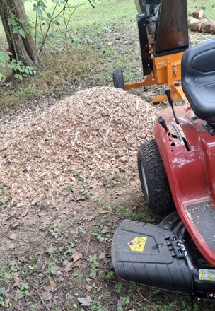
5) I bought a new mower AND 6" chipper and put it to use starting to clear some of the fallen trees and raising tree canopies. My brother removed the 4 dead mowers but hasn't yet found someone that wants them (I rebuilt one that died again but decided it was going to take forever, so punted).
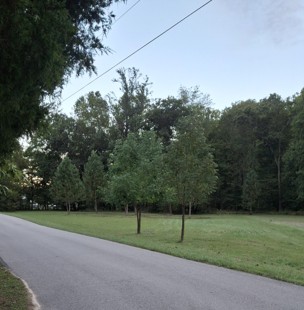
Tree (7 tulip poplar) canopies raised for easier mowing. I also removed a bunch of brush and two cedar trees.
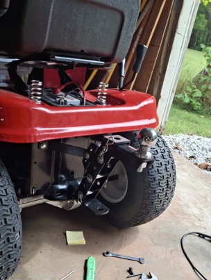
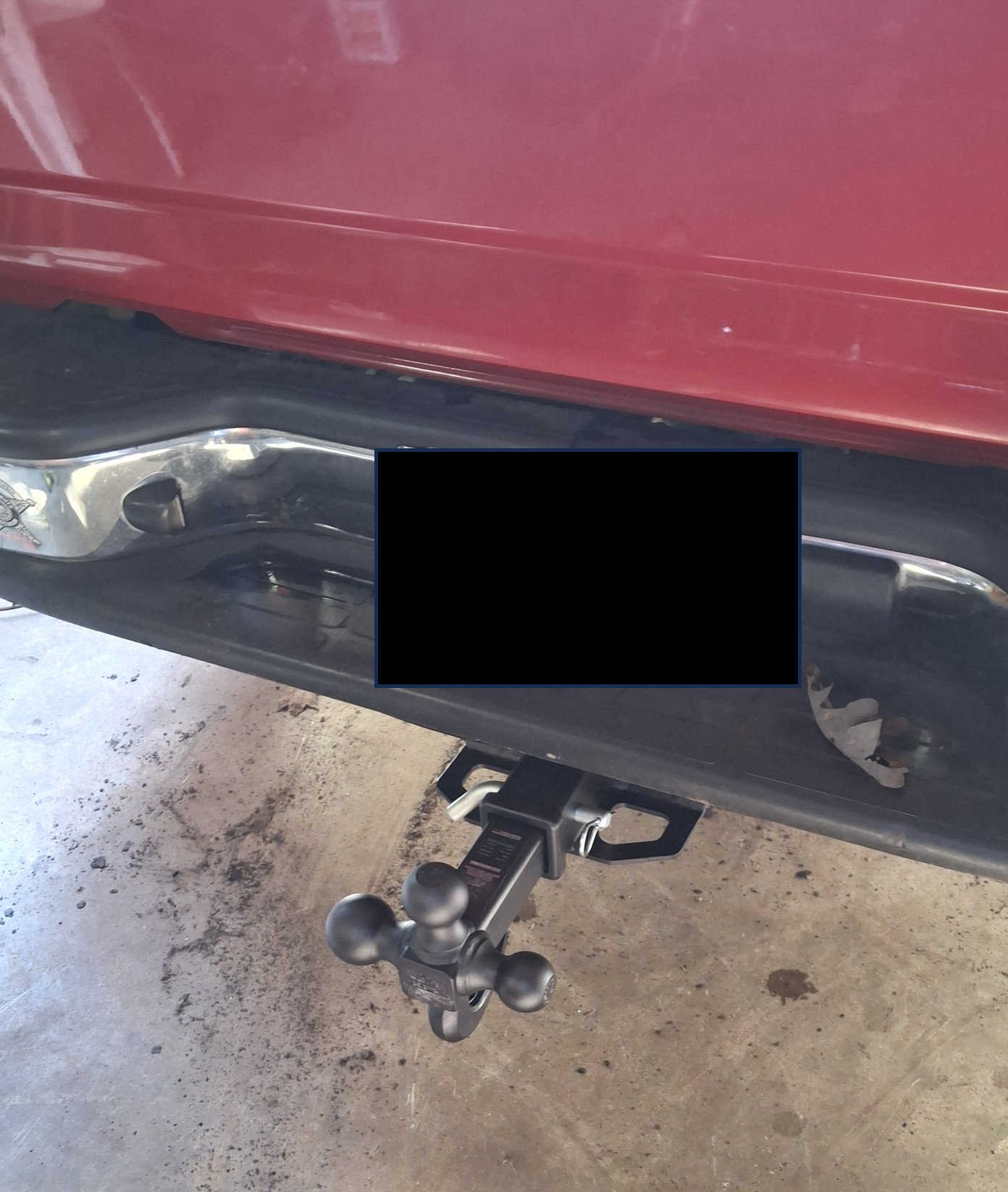
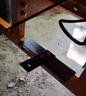
6) Installed new hitches so I can pull the chipper around easier.
The truck is severely rusted. The bumper is almost gone, just a shell of chrome. So I added a new "class 4" hitch. If I actually pulled 10,000lbs, the truck would probably split in the middle though :(
Custom hitch for the chipper to pull the garden wagon behind with various tools. I didn't start on the garden wagon repair. I was waiting for the pest control company to eliminate the hornets swarming around it.
Edited by dfwallis - 28 Sep 2026 at 2:49pm
|
|
1952 CA13092, CA Pickup Plow, CA Cultivator, CA Two Row Planter, Dunham-Lehr GC78 Disc, Grader Blade, 3pt Fm180 Finish Mower
|
|
Les Kerf
Orange Level
Joined: 08 May 2020
Location: Idaho
Points: 1923
|
Post Options
Thanks(0)
Quote Reply
Posted: 28 Sep 2026 at 2:59pm |
dfwallis wrote:
...that random miss issue has returned (with a TSX670 carb, not the original TSX486). It does not happen at idle or when under load... |
Hmmm... this sure is a puzzler
These carburetors have a 'back suction' circuit that comes into play at part throttle and medium load, the purpose being to lean out the mixture for improved fuel economy. There is a small slot just just above the idle port, when the throttle is opened just above an idle, this slot is exposed to manifold vacuum; the back suction slot is connected by a small passageway to the fuel chamber.
The vacuum applied above the fuel reduces the available pressure (normally one atmosphere) which then pushes a reduced amount of fuel up into the air flow, thus producing a leaner mixture. As the throttle opens further, there is less vacuum applied through the back pressure circuit and the mixture progressively richens until at some point around 3/4 throttle opening the back pressure circuit has no effect and the mixture is controlled entirely by the main jet and the fuel level.
Trouble is, today's gasoline is not the same stuff that the carburetor designers were dealing with 'back in the day'. I have read on one of the carburetor sites (maybe Mike's Carburetors?) that it is necessary in some cases to raise the float level slightly to get these carburetors to behave at mid-range on modern fuel.
I have found these back suction passageways to be quite a challenge to clean
|
|
dfwallis
Orange Level
Joined: 09 Mar 2023
Location: Texas / Indiana
Points: 1052
|
Post Options
Thanks(0)
Quote Reply
Posted: 28 Sep 2026 at 3:28pm |
Les Kerf wrote:
dfwallis wrote:
...that random miss issue has returned (with a TSX670 carb, not the original TSX486). It does not happen at idle or when under load... |
Hmmm... this sure is a puzzler
These carburetors have a 'back suction' circuit that comes into play at part throttle and medium load, the purpose being to lean out the mixture for improved fuel economy. There is a small slot just just above the idle port, when the throttle is opened just above an idle, this slot is exposed to manifold vacuum; the back suction slot is connected by a small passageway to the fuel chamber.
The vacuum applied above the fuel reduces the available pressure (normally one atmosphere) which then pushes a reduced amount of fuel up into the air flow, thus producing a leaner mixture. As the throttle opens further, there is less vacuum applied through the back pressure circuit and the mixture progressively richens until at some point around 3/4 throttle opening the back pressure circuit has no effect and the mixture is controlled entirely by the main jet and the fuel level.
Trouble is, today's gasoline is not the same stuff that the carburetor designers were dealing with 'back in the day'. I have read on one of the carburetor sites (maybe Mike's Carburetors?) that it is necessary in some cases to raise the float level slightly to get these carburetors to behave at mid-range on modern fuel.
I have found these back suction passageways to be quite a challenge to clean
|
:( both carburetors were "professionally" rebuilt for big $$$ (not to mention my repeated attempts on the 486). I'm tempted to take the tractor to a local pulling tractor builder for diagnosis. I had taken it to the former AGCO dealer (descendent of its original AC dealer where it was bought), but it came back the same.
|
|
1952 CA13092, CA Pickup Plow, CA Cultivator, CA Two Row Planter, Dunham-Lehr GC78 Disc, Grader Blade, 3pt Fm180 Finish Mower
|
|
wjohn
Orange Level

Joined: 19 Jan 2010
Location: KS
Points: 2617
|
Post Options
Thanks(0)
Quote Reply
Posted: 28 Sep 2026 at 8:30pm |
dfwallis wrote:
I did replace the paper fuel filter with a free flowing mesh filter. I believe one of the issues was the paper filter not working so well with a gravity feed delivery system that is almost horizontal from the tank. |
I was unable to find a paper filter that didn't make my CA an anemic dog, and even after trying some of the largest micron filters that my local auto parts stores had, ended up giving up. I took the tank off, cleaned the rust/scale out of it as best I could, and put in a new sediment bowl assembly. It ran well after that.
My IH Super M has been running a larger micron paper filter since I got it and it has never seemed to cause it any issues. I do like to run them for at least a while at first especially with a new tractor and a tank that may have some junk in it, but it seems not all tractors are happy with that as Les mentioned.
|
|
1939 B, 1940 B, 1941 WC, 1951 WD, 1952 CA, 1956 WD-45
|
|
dfwallis
Orange Level
Joined: 09 Mar 2023
Location: Texas / Indiana
Points: 1052
|
Post Options
Thanks(0)
Quote Reply
Posted: 28 Sep 2026 at 8:41pm |
wjohn wrote:
dfwallis wrote:
I did replace the paper fuel filter with a free flowing mesh filter. I believe one of the issues was the paper filter not working so well with a gravity feed delivery system that is almost horizontal from the tank. |
I was unable to find a paper filter that didn't make my CA an anemic dog, and even after trying some of the largest micron filters that my local auto parts stores had, ended up giving up. I took the tank off, cleaned the rust/scale out of it as best I could, and put in a new sediment bowl assembly. It ran well after that.
My IH Super M has been running a larger micron paper filter since I got it and it has never seemed to cause it any issues. I do like to run them for at least a while at first especially with a new tractor and a tank that may have some junk in it, but it seems not all tractors are happy with that as Les mentioned. |
The stainless steel mesh filter is definitely more free flowing than the paper. But I can't actually say there was significant blockage from blowing through the paper filter which I think should have caused a problem. I may run a test with the extra filter removed though. The tank was thoroughly de-rusted, cleaned, coated internally with POR15 and has new mesh screen in the tank and a new bowl/valve (aftermarket). There's absolutely no indication of any sediment/water in either the bowl or the filter. It looks pristine.
Edited by dfwallis - 29 Sep 2026 at 2:53pm
|
|
1952 CA13092, CA Pickup Plow, CA Cultivator, CA Two Row Planter, Dunham-Lehr GC78 Disc, Grader Blade, 3pt Fm180 Finish Mower
|
|
Les Kerf
Orange Level
Joined: 08 May 2020
Location: Idaho
Points: 1923
|
Post Options
Thanks(1)
Quote Reply
Posted: 29 Sep 2026 at 11:35am |
dfwallis wrote:
... It does not happen at idle or when under load...
|
The fact that it does not miss under load indicates that there is adequate fuel delivery to the carburetor regardless of what fuel filter is in place.
If it is indeed too lean at part throttle/light loads then raising the fuel level may help; this also might result in being too rich under heavy load. The idle is easily corrected for mixture.
If it were mine I would connect a clear plastic tube at the drain and secure it so as to be able to monitor the actual fuel level while running, then experiment from there.
A dynamometer would be most handy  |
|
dfwallis
Orange Level
Joined: 09 Mar 2023
Location: Texas / Indiana
Points: 1052
|
Post Options
Thanks(0)
Quote Reply
Posted: 29 Sep 2026 at 2:14pm |
Les Kerf wrote:
dfwallis wrote:
... It does not happen at idle or when under load...
|
The fact that it does not miss under load indicates that there is adequate fuel delivery to the carburetor regardless of what fuel filter is in place.
If it is indeed too lean at part throttle/light loads then raising the fuel level may help; this also might result in being too rich under heavy load. The idle is easily corrected for mixture.
If it were mine I would connect a clear plastic tube at the drain and secure it so as to be able to monitor the actual fuel level while running, then experiment from there.
A dynamometer would be most handy |
I wonder if I should try high octane?
|
|
1952 CA13092, CA Pickup Plow, CA Cultivator, CA Two Row Planter, Dunham-Lehr GC78 Disc, Grader Blade, 3pt Fm180 Finish Mower
|
|
Les Kerf
Orange Level
Joined: 08 May 2020
Location: Idaho
Points: 1923
|
Post Options
Thanks(1)
Quote Reply
Posted: 29 Sep 2026 at 3:24pm |
dfwallis wrote:
...I wonder if I should try high octane? |
If you are currently using gasoline with ethanol then it may be worthwhile to try some non-ethanol premium. It won't be much different but if it is now running borderline lean then it could help a bit.
I only run non-ethanol premium in my tractors, not because they need the higher octane rating but because I don't run them enough to keep the donkey snot from forming in my carburetors. If I were actually working them doing real field work I would cheerfully run the least expensive fuel available.
|
|
dfwallis
Orange Level
Joined: 09 Mar 2023
Location: Texas / Indiana
Points: 1052
|
Post Options
Thanks(0)
Quote Reply
Posted: 29 Sep 2026 at 4:01pm |
Les Kerf wrote:
dfwallis wrote:
...I wonder if I should try high octane? |
If you are currently using gasoline with ethanol then it may be worthwhile to try some non-ethanol premium. It won't be much different but if it is now running borderline lean then it could help a bit.
I only run non-ethanol premium in my tractors, not because they need the higher octane rating but because I don't run them enough to keep the donkey snot from forming in my carburetors. If I were actually working them doing real field work I would cheerfully run the least expensive fuel available.
|
Countrymark offers E0 90 octane. I might give it a try.
|
|
1952 CA13092, CA Pickup Plow, CA Cultivator, CA Two Row Planter, Dunham-Lehr GC78 Disc, Grader Blade, 3pt Fm180 Finish Mower
|
|