| Author |
 Topic Search Topic Search  Topic Options Topic Options
|
jturano11 
Bronze Level

Joined: 26 Mar 2010
Location: Pennsylvania
Points: 34
|
 Post Options Post Options
 Thanks(0) Thanks(0)
 Quote Quote  Reply Reply
 Topic: My hd5g loader Topic: My hd5g loader
Posted: 13 Dec 2016 at 5:23pm |
|
I am currently trying to rebush my pins on Mt loader reservoirs. Does anyone know how to remove the pins. I don't know if they're drawn in with the rear bolt as a press fit or its like a regular pin on a loader bucket. It's in a spot you can't use a sledge. I can heat it but how can I pull it out? The pin has a hole thru the head ,is this for some type of removal aid?
Can anyone shed some light on this?
|
 |
|
Sponsored Links
|
|
 |
Dozer 
Orange Level

Joined: 16 Aug 2011
Location: SW New York
Points: 689
|
 Post Options Post Options
 Thanks(0) Thanks(0)
 Quote Quote  Reply Reply
 Posted: 13 Dec 2016 at 6:40pm Posted: 13 Dec 2016 at 6:40pm |
|
There is a master pin and master link that are different. Usually the master link is slightly longer. Position the master pin on the idler or sprocket use a drift and a large hammer to remove the master pin. be aware that the track is going to fly appart when the pin is removed. The master pin is fitted looser the other pins are press fit and require a press to remove. Have you located new pins and bushings?
Some aftermarket pins and bushings are made slip fit. Those pins are welded to the links at assembly.
|
 |
DMiller 
Orange Level Access

Joined: 14 Sep 2009
Location: Hermann, Mo
Points: 29412
|
 Post Options Post Options
 Thanks(0) Thanks(0)
 Quote Quote  Reply Reply
 Posted: 13 Dec 2016 at 6:59pm Posted: 13 Dec 2016 at 6:59pm |
|
Put photo up of what you are looking at. I think there be some confusion starting.
|
 |
jturano11 
Bronze Level

Joined: 26 Mar 2010
Location: Pennsylvania
Points: 34
|
 Post Options Post Options
 Thanks(0) Thanks(0)
 Quote Quote  Reply Reply
 Posted: 13 Dec 2016 at 8:53pm Posted: 13 Dec 2016 at 8:53pm |
|
I am not referring to the Trax master pin. I am referring to the pin that holds the reservoir /loader frame to the truck frame. It bolts to the rigid beam front and has a pin in the rear behind the drive sprocket.
|
 |
wayneIA 
Orange Level

Joined: 17 Oct 2009
Location: Waverly, IA
Points: 268
|
 Post Options Post Options
 Thanks(0) Thanks(0)
 Quote Quote  Reply Reply
 Posted: 13 Dec 2016 at 9:13pm Posted: 13 Dec 2016 at 9:13pm |
|
If you are talking about the pin I think you are. The one inside the frame by the final drive. You are looking at part of the undercarriage system, this is the pivot pin for when you have a dozer or ag tractor with a leaf spring support in place of the rigid cross beam that your loader is bolted to now to allow the tracks to oscillate with the terrain. My HD5 only has bolts in the front on the rigid beam and rear just ahead of the final drive that holds the entire loader frame on if I remember correctly.
|
 |
jturano11 
Bronze Level

Joined: 26 Mar 2010
Location: Pennsylvania
Points: 34
|
 Post Options Post Options
 Thanks(0) Thanks(0)
 Quote Quote  Reply Reply
 Posted: 14 Dec 2016 at 12:35am Posted: 14 Dec 2016 at 12:35am |
|
That's the one but it doesn't ocilate .it holds the rear end of the loader frame tight to the truck frame. When the pin and bushings are worn,the loader frame moves back and forth. I want to rebush it.
|
 |
jturano11 
Bronze Level

Joined: 26 Mar 2010
Location: Pennsylvania
Points: 34
|
 Post Options Post Options
 Thanks(0) Thanks(0)
 Quote Quote  Reply Reply
 Posted: 14 Dec 2016 at 12:39am Posted: 14 Dec 2016 at 12:39am |
|
The front is bolted the rear is pin and bushing.
|
 |
DMiller 
Orange Level Access

Joined: 14 Sep 2009
Location: Hermann, Mo
Points: 29412
|
 Post Options Post Options
 Thanks(0) Thanks(0)
 Quote Quote  Reply Reply
 Posted: 14 Dec 2016 at 5:10am Posted: 14 Dec 2016 at 5:10am |
|
You will need a service manual. Is not so simple to remove pin replace bushing as is a press fit assembly into the truck frame casting.
|
 |
jturano11 
Bronze Level

Joined: 26 Mar 2010
Location: Pennsylvania
Points: 34
|
 Post Options Post Options
 Thanks(0) Thanks(0)
 Quote Quote  Reply Reply
 Posted: 14 Dec 2016 at 7:27am Posted: 14 Dec 2016 at 7:27am |
|
I have both manuals.there is one from Allis for the tractor and another from tractomotive. I don't see loader frame removal. As well as I don't see main frame removal or rigid beam removal. I have help ,and have the machines stripped down to the loader frame. Noone here can understand how to pull the pin in an area like that.
Guess we need the experience of someone who actually has done it.
|
 |
jturano11 
Bronze Level

Joined: 26 Mar 2010
Location: Pennsylvania
Points: 34
|
 Post Options Post Options
 Thanks(0) Thanks(0)
 Quote Quote  Reply Reply
 Posted: 14 Dec 2016 at 7:35am Posted: 14 Dec 2016 at 7:35am |
|
I'm not sure of anything.are you sure it's a press fit? Maybe it's rusty.I saw it was shot and moving maybe the 7/8 hole in the pin is for turning and the rear has threads and the nut is a lock nut? Maybe it's just a pin and bushing. All tractomotive gave me is a diagram. I'll look at it tonight but I doubt it'll help.I think I need someone who has this experience.
|
 |
jturano11 
Bronze Level

Joined: 26 Mar 2010
Location: Pennsylvania
Points: 34
|
 Post Options Post Options
 Thanks(0) Thanks(0)
 Quote Quote  Reply Reply
 Posted: 14 Dec 2016 at 7:37am Posted: 14 Dec 2016 at 7:37am |
|
There's got to be a way.
|
 |
wayneIA 
Orange Level

Joined: 17 Oct 2009
Location: Waverly, IA
Points: 268
|
 Post Options Post Options
 Thanks(0) Thanks(0)
 Quote Quote  Reply Reply
 Posted: 14 Dec 2016 at 7:48am Posted: 14 Dec 2016 at 7:48am |
|
If I remember correctly there are two saddles one on each side of the truck arm that holds the pin. You take 4 bolts out and the bottom half of the saddles drop off then you can jack the frame of the crawler up and then knock the pins out. There is a dowel pin from above that goes into a hole in the pin to keep it from working out of the saddle and the truck frame. It's been a few years since I had my truck frames off and can't remember exactly how it worked.
|
 |
Sugarmaker 
Orange Level

Joined: 12 Jul 2013
Location: Albion PA
Points: 8167
|
 Post Options Post Options
 Thanks(0) Thanks(0)
 Quote Quote  Reply Reply
 Posted: 14 Dec 2016 at 8:54am Posted: 14 Dec 2016 at 8:54am |
|
I have no clue, but pictures of the problem might help a lot??? Sounds like big, heavy, awkward, rusty, tight space, problem to me!:)
Dad always said " someone had to put it together, we should be able to take it apart, repair it, and reassemble too"! Did you call Mel?
Regards,
Chris
|
|
D17 1958 (NFE), WD45 1954 (NFE), WD 1952 (NFE), WD 1950 (WFE), Allis F-40 forklift, Allis CA, Allis D14, Ford Jubilee, Many IH Cub Cadets, 32 Ford Dump, 65 Comet.
|
 |
AC Mel 
Orange Level Access

Joined: 23 Jan 2010
Location: N.Ca.
Points: 1099
|
 Post Options Post Options
 Thanks(0) Thanks(0)
 Quote Quote  Reply Reply
 Posted: 14 Dec 2016 at 9:30am Posted: 14 Dec 2016 at 9:30am |
|
Ok, I'm on it. I'm just as confused as everyone else. Enough that I would like to know more. Gotta be something simple, cause I always brag to old Cat and International owners how easy ACs were to work on. I sent Joe a PM and also to his email for pictures. Stand by
|
 |
Coke-in-MN 
Orange Level Access

Joined: 12 Sep 2009
Location: Afton MN
Points: 41184
|
 Post Options Post Options
 Thanks(0) Thanks(0)
 Quote Quote  Reply Reply
 Posted: 14 Dec 2016 at 10:06am Posted: 14 Dec 2016 at 10:06am |
|
As close as I got to replacing is i had one of the saddles cracked from the main casting - welded it back into place and reattached it so truck frame did not move - was on a HD5B that I had bought where they ran the machine with busted axle by outboard bearing on truck frame which allowed it to pivot and break main casting of rear . was the bottom of the steering clutch case area so no oil leakage .
|
|
Faith isn't a jump in the dark. It is a walk in the light. Faith is not guessing; it is knowing something.
"Challenges are what make life interesting; overcoming them is what makes life meaningful."
|
 |
AC Mel 
Orange Level Access

Joined: 23 Jan 2010
Location: N.Ca.
Points: 1099
|
 Post Options Post Options
 Thanks(0) Thanks(0)
 Quote Quote  Reply Reply
 Posted: 14 Dec 2016 at 3:19pm Posted: 14 Dec 2016 at 3:19pm |
Ok, Joe sent me some pictures,so everyone can be on t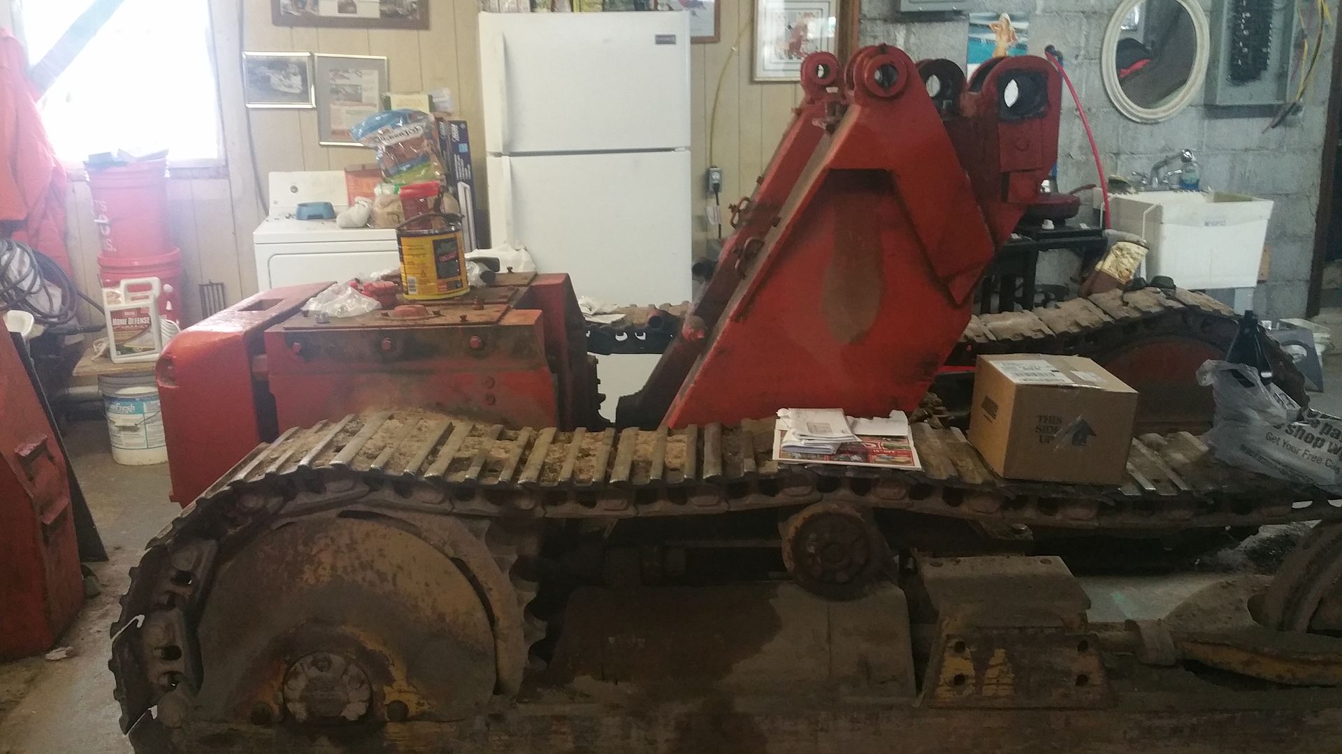
he same page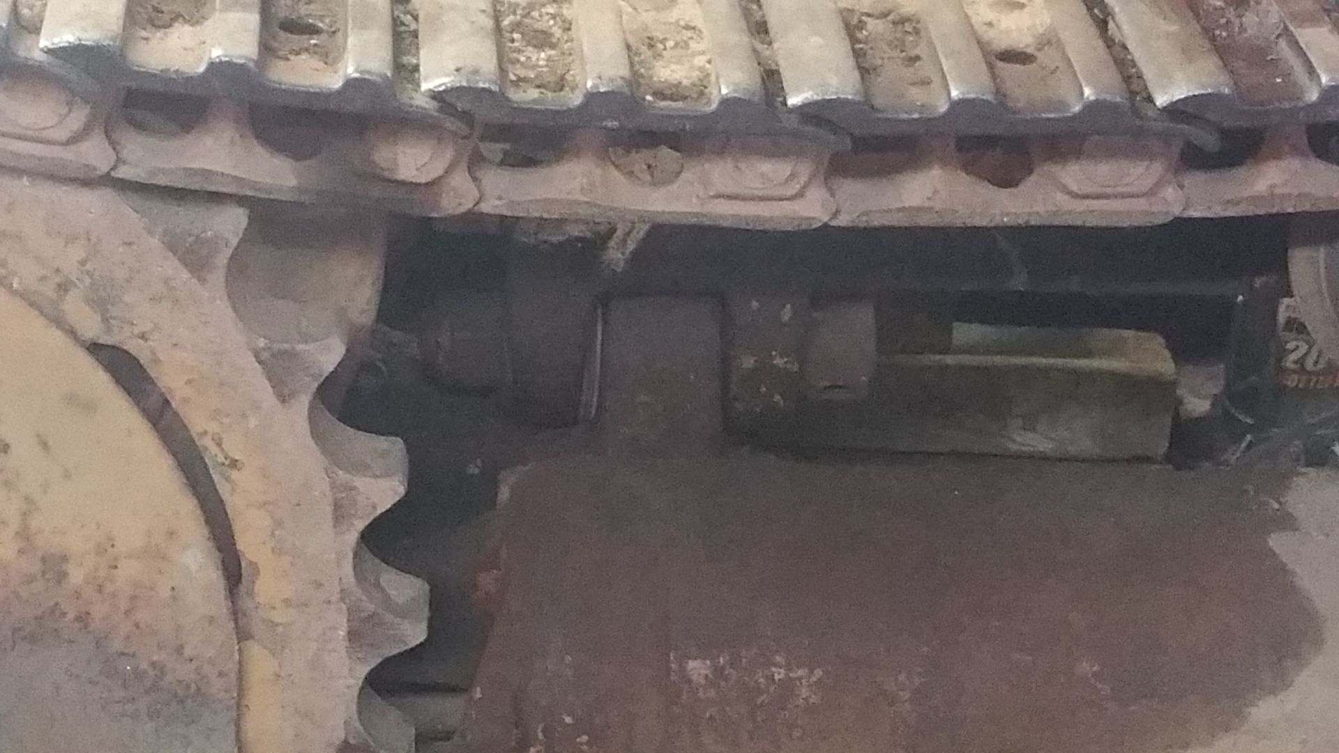 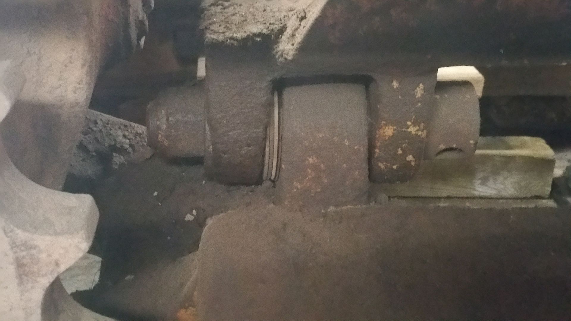 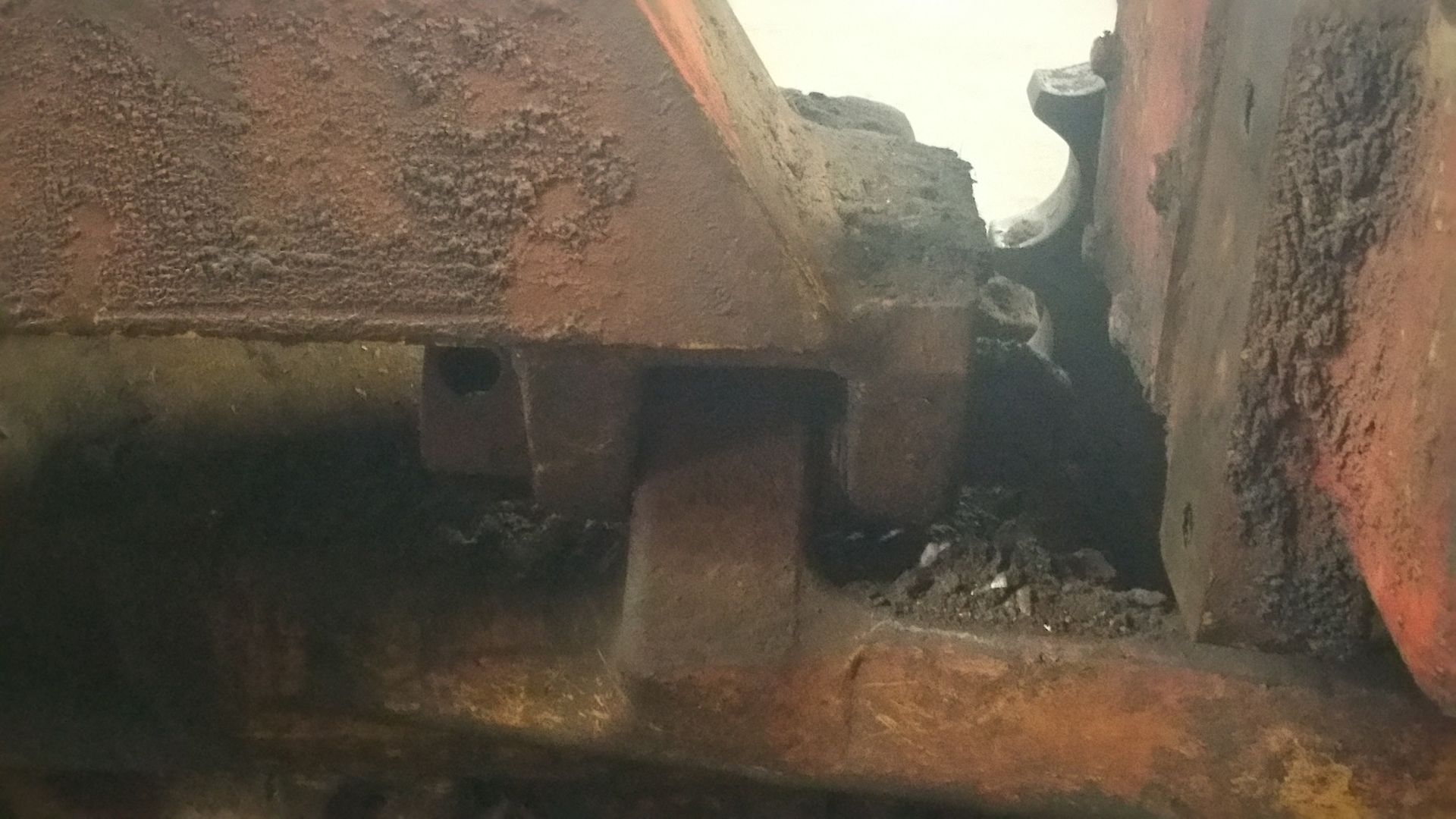 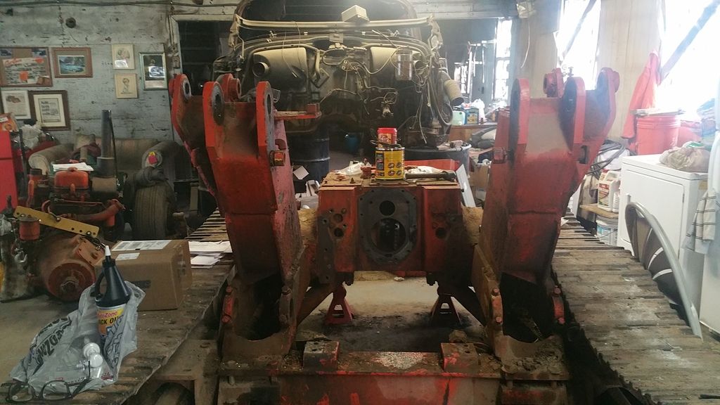 Can't find our TS-5 parts book. But I think the HD6 might be the same (MAYBE!!!) so here is the info for the early HD6. There are some tapered bushings in there that could probably cause a lot of heartburn trying to get the pin out. Also the Tractomotive book gives no info on removal. Can't find our TS-5 parts book. But I think the HD6 might be the same (MAYBE!!!) so here is the info for the early HD6. There are some tapered bushings in there that could probably cause a lot of heartburn trying to get the pin out. Also the Tractomotive book gives no info on removal.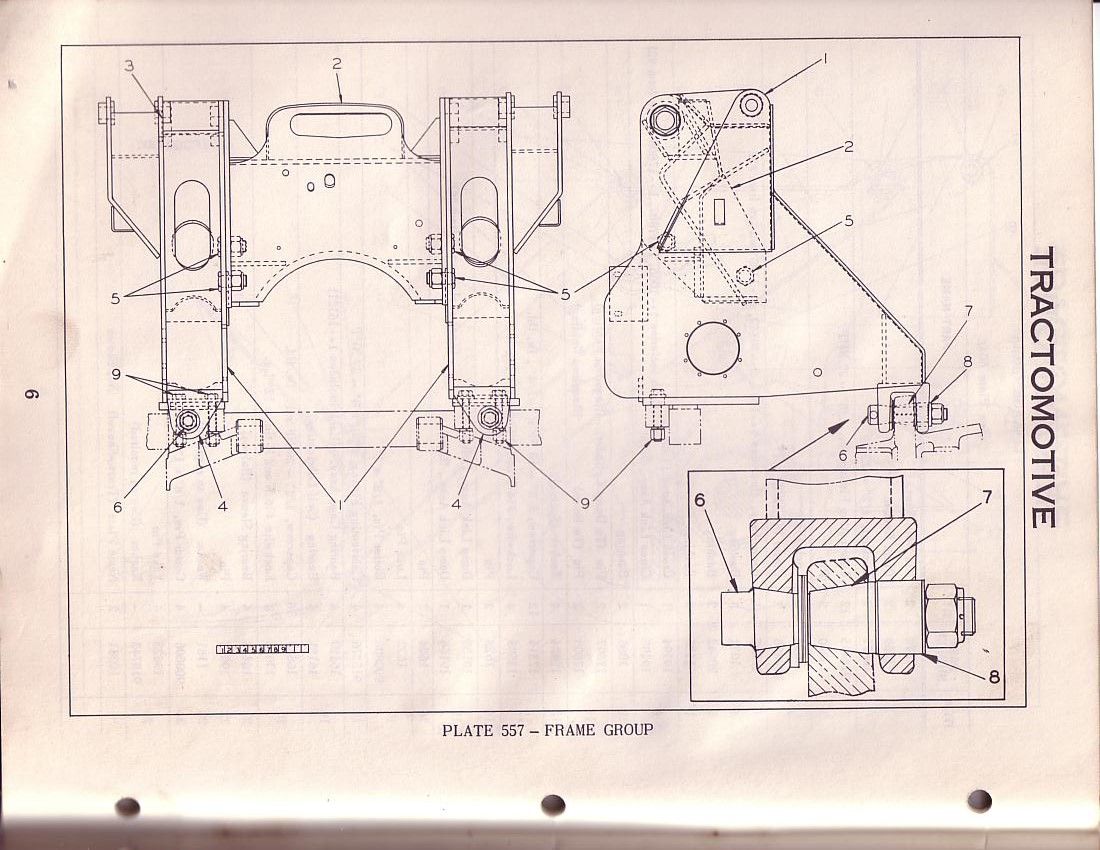
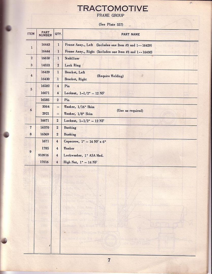 Hopefully the pictures will help some one who has done this chime in. The only thing we've done is weld that bracket back to the swing frame. I'll keep looking for the HD5 Tractomotive book. (also keep up the good work looks like it could be a super restoration!!) Again still not sure about the tapered bushings. Hopefully the pictures will help some one who has done this chime in. The only thing we've done is weld that bracket back to the swing frame. I'll keep looking for the HD5 Tractomotive book. (also keep up the good work looks like it could be a super restoration!!) Again still not sure about the tapered bushings.
|
 |
Coke-in-MN 
Orange Level Access


Joined: 12 Sep 2009
Location: Afton MN
Points: 41184
|
 Post Options Post Options
 Thanks(0) Thanks(0)
 Quote Quote  Reply Reply
 Posted: 14 Dec 2016 at 3:41pm Posted: 14 Dec 2016 at 3:41pm |
Just shimmed that area with split washers to try to take some slop out of areas I thought it was the rear of the truck frame where it meets the rear case on the inside . It seems that area where the loader mounts to the cross beam on the HD5G has had movement no matter what . All 4 machines I had seemed to have slop in that place
|
|
Faith isn't a jump in the dark. It is a walk in the light. Faith is not guessing; it is knowing something.
"Challenges are what make life interesting; overcoming them is what makes life meaningful."
|
 |
jturano11 
Bronze Level

Joined: 26 Mar 2010
Location: Pennsylvania
Points: 34
|
 Post Options Post Options
 Thanks(0) Thanks(0)
 Quote Quote  Reply Reply
 Posted: 14 Dec 2016 at 6:20pm Posted: 14 Dec 2016 at 6:20pm |
|
My dad said they all wear outI never saw one that wasn't .he had his linebored and put hd7 tapered pins in.claimed he never had a problem since. My dad said his were not tapered. Maybe mine is because I have a1955and his was a 1953 I don't know.
There must be a way. He's the only one I know would know and he's not around to tell.
|
 |
Sugarmaker 
Orange Level


Joined: 12 Jul 2013
Location: Albion PA
Points: 8167
|
 Post Options Post Options
 Thanks(0) Thanks(0)
 Quote Quote  Reply Reply
 Posted: 14 Dec 2016 at 8:28pm Posted: 14 Dec 2016 at 8:28pm |
|
Well from the easy chair and on paper this doesn't look too bad!:)
The work Mel did and the pictures tell a lot about the problem.
I would put a stop pin (3/8 dia??) through the hole in the head of the custom bolt. This allows you to heat and remove the nut while holding the head from turning. If you get that done then the bolt should move out of the hole (away from the nut end) and release the taper. A porta power might be needed, and some heat on the taper. It looks like it may be more than a 7 degree taper so it should not be a locking fit taper, but may be rusted/stuck. Do both sides and then lift the frame up to remove the inner tapered portions. Take lots of pictures!
Easy, peasy, lemon squeezy! Yea right:)
Not knowing whether its tapered inside or not, it still looks like how it has to come apart. We just don't have a full cross section of the shank with the nut on the threaded end. I would bet you breakfast that Mel has it nailed with the picture he found!
Item 8 is a spacer and should allow the frame to be lifted up after the custom bolt is out. Then you can see item 7 stuck in the lower frame ear and see how bad it is worn.
They did not use a standard bolt for item 6 because it had to have the taper turned on it.
I think some heat in the right places will allow you to win this battle. When you get it apart you may need some new tapered parts like item 7?
Regards,
Chris
Edited by Sugarmaker - 14 Dec 2016 at 8:33pm
|
|
D17 1958 (NFE), WD45 1954 (NFE), WD 1952 (NFE), WD 1950 (WFE), Allis F-40 forklift, Allis CA, Allis D14, Ford Jubilee, Many IH Cub Cadets, 32 Ford Dump, 65 Comet.
|
 |
jturano11 
Bronze Level

Joined: 26 Mar 2010
Location: Pennsylvania
Points: 34
|
 Post Options Post Options
 Thanks(0) Thanks(0)
 Quote Quote  Reply Reply
 Posted: 14 Dec 2016 at 9:58pm Posted: 14 Dec 2016 at 9:58pm |
|
We got the rear bolt off w/o needing the 7/8 rod to hold it.problem is that we have a Porta power but you cannot push against the final drive housing.and you have no room to swing an appropriate size sledge. I think maybe the truck frame must be dropped and rolled forward. I hate to say it but how else can you gain access. The pin has to come out thu the front and there's no access from the rear. Unless you can somehow pull from the 7/8 hole towards the front. Sounds dangerous.
|
 |
wayneIA 
Orange Level

Joined: 17 Oct 2009
Location: Waverly, IA
Points: 268
|
 Post Options Post Options
 Thanks(0) Thanks(0)
 Quote Quote  Reply Reply
 Posted: 15 Dec 2016 at 1:18am Posted: 15 Dec 2016 at 1:18am |
|
Sorry for the miss-leading information earlier, I was under the understanding you were working on the pins for the truck frames underneath the machine. I'll have to look at mine now, I don't remember that the rear of my loader attaches that way.
|
 |
Sugarmaker 
Orange Level


Joined: 12 Jul 2013
Location: Albion PA
Points: 8167
|
 Post Options Post Options
 Thanks(0) Thanks(0)
 Quote Quote  Reply Reply
 Posted: 15 Dec 2016 at 8:38am Posted: 15 Dec 2016 at 8:38am |
|
I agree that it looks like the pin has to come out towards the front of the machine. The more I look at Mels picture this may be a locking taper and will only release with a sharp blow? Can you put a short 7/8 bar in the cross hole? Maybe sticking out each side about a inch? If so you might be able to use that and some heat on the tapered joint to get the taper loose. Maybe then drive a wedge, like a ball joint tool between the short 7/8 cross pin and the casting, both sides. Once its loose and the weight is off the frame it should fall out, maybe unless the inside dia. is a tight fit? But you said that's the worn part so should be loose.
Trying to think of a way to use that nut as the force to push the pin out?? You said you cant push against the drive box, so I guess that's not a option?
More pictures as you progress please.
Will this frame lift up and out or do the tracks have to come off??
BTW you have a big project! What's the truck project in the back ground?
Regards,
Chris
Edited by Sugarmaker - 15 Dec 2016 at 8:46am
|
|
D17 1958 (NFE), WD45 1954 (NFE), WD 1952 (NFE), WD 1950 (WFE), Allis F-40 forklift, Allis CA, Allis D14, Ford Jubilee, Many IH Cub Cadets, 32 Ford Dump, 65 Comet.
|
 |
jturano11 
Bronze Level

Joined: 26 Mar 2010
Location: Pennsylvania
Points: 34
|
 Post Options Post Options
 Thanks(0) Thanks(0)
 Quote Quote  Reply Reply
 Posted: 15 Dec 2016 at 2:06pm Posted: 15 Dec 2016 at 2:06pm |
|
If I get the pins out, the frame will come out w/o removing trax.
If I'm unsuccessful using the 7/8 hole in front someway for extraction, I think it's nessasary to break the trax apart, drop and roll the truck frame forward. Can't afford to Crack the final drive housing pressing against it. Also not much room back there even to try that .
That's a car restoration project in the back.
|
 |
gemdozer 
Orange Level

Joined: 17 Sep 2009
Points: 940
|
 Post Options Post Options
 Thanks(0) Thanks(0)
 Quote Quote  Reply Reply
 Posted: 15 Dec 2016 at 2:25pm Posted: 15 Dec 2016 at 2:25pm |
|
You could remove some pression betwen the truck frame and loder frame to removed the bolt she must have a lipp and turning by the front pine hole 7/8 it could help and you could push on the nut with a pitch bar by prying on housing
|
 |
DMiller 
Orange Level Access

Joined: 14 Sep 2009
Location: Hermann, Mo
Points: 29412
|
 Post Options Post Options
 Thanks(0) Thanks(0)
 Quote Quote  Reply Reply
 Posted: 15 Dec 2016 at 4:00pm Posted: 15 Dec 2016 at 4:00pm |
|
Need to get a porta power or something to put some pressure on the threaded end, then take a ten pound and pop the side of the truck frame really hard. Was the only way I got the one out of my donor 7G. Are a real bite how they made these instead of just bolting the loader frame to the frame. And I have to go thru it again, to pull the right hand truck and pull my right final apart.
|
 |
Dozer 
Orange Level

Joined: 16 Aug 2011
Location: SW New York
Points: 689
|
 Post Options Post Options
 Thanks(0) Thanks(0)
 Quote Quote  Reply Reply
 Posted: 15 Dec 2016 at 5:07pm Posted: 15 Dec 2016 at 5:07pm |
|
It should be a 2 piece bushing so you can separate it when you get the pin out. P/N 16370 tapered bushing P/N 16379 stays with the loader frame
|
 |
DiyDave 
Orange Level Access


Joined: 11 Sep 2009
Location: Gambrills, MD
Points: 50462
|
 Post Options Post Options
 Thanks(0) Thanks(0)
 Quote Quote  Reply Reply
 Posted: 15 Dec 2016 at 6:18pm Posted: 15 Dec 2016 at 6:18pm |
Get the parts and burn it out... 
|
 |
Sugarmaker 
Orange Level


Joined: 12 Jul 2013
Location: Albion PA
Points: 8167
|
 Post Options Post Options
 Thanks(0) Thanks(0)
 Quote Quote  Reply Reply
 Posted: 15 Dec 2016 at 9:20pm Posted: 15 Dec 2016 at 9:20pm |
|
Another idea.
Make a puller. take a tube same OD as the end where the 7/8 rod goes through, and about 6 inches long. Drill a hole through it to allow a 7/8 rod to pass through it and the pin you want to pull. Place a short piece of 7/8 rod through both.
Weld or thread a piece of 2 inch dia? all thread 24 inch? long into the new slip on sleeve. make the all thread long enough to reach a new bracket which would be bolted to the front structure/ frame?. add a good grade 8 nut and put some tension on the pin. heat the front portion of the casting where the pin sets in the taper, per Mels sketch. and keep applying some pressure with the nut on the all thread. Might come loose with a bang? That way your pulling rather than pushing.
regards,
Chris
|
|
D17 1958 (NFE), WD45 1954 (NFE), WD 1952 (NFE), WD 1950 (WFE), Allis F-40 forklift, Allis CA, Allis D14, Ford Jubilee, Many IH Cub Cadets, 32 Ford Dump, 65 Comet.
|
 |
Sugarmaker 
Orange Level


Joined: 12 Jul 2013
Location: Albion PA
Points: 8167
|
 Post Options Post Options
 Thanks(0) Thanks(0)
 Quote Quote  Reply Reply
 Posted: 15 Dec 2016 at 9:30pm Posted: 15 Dec 2016 at 9:30pm |
|
Ok maybe there is not enough room to get by the upper idler?
I really think the key to this is heating with a torch to enlarge the casting. And lots of PB Blaster too!
Another approach:
Make a sleeve larger that the portion of the pin to be pulled out, and just long enough that would cover 1/4 of the 7/8 hole when slid over the pin up against the casting. Heat the casting and drive a drift pin into the 7/8 hole, if its at a angle that will let you??? If not this may not work?
Regards,
Chris
Edited by Sugarmaker - 15 Dec 2016 at 9:32pm
|
|
D17 1958 (NFE), WD45 1954 (NFE), WD 1952 (NFE), WD 1950 (WFE), Allis F-40 forklift, Allis CA, Allis D14, Ford Jubilee, Many IH Cub Cadets, 32 Ford Dump, 65 Comet.
|
 |
donoman 
Silver Level

Joined: 18 Feb 2015
Location: New Zealand
Points: 117
|
 Post Options Post Options
 Thanks(0) Thanks(0)
 Quote Quote  Reply Reply
 Posted: 15 Dec 2016 at 9:32pm Posted: 15 Dec 2016 at 9:32pm |
With my 6G we had success using stumpy portapower ram and heating the big eyes with the gas torch on another occasion we cut a slot in the eyes to relieve the pressure in the tapered shaft in each case we had new shafts machined up out of 4140 steel. unless it is loose there is no easy way that we have found other than the above.
|
 |


 Topic Options

 Post Options
 Thanks(0)


