| Author |
 Topic Search Topic Search  Topic Options Topic Options
|
Allis dave 
Orange Level

Joined: 10 May 2012
Location: Northern IN
Points: 2847
|
 Post Options Post Options
") Thanks(1) Thanks(1)
 Quote Quote  Reply Reply
 Topic: WD45 rebuild progress Topic: WD45 rebuild progress
Posted: 04 Aug 2016 at 8:18am |
I took my WD45 226 head off last Winter to fix a leaking head gasket and found some scoring on the sleeves and pistons. I decided it was time for a rebuild to help the 45 last the rest of my lifetime. There was a lot of junk in the oil pan, so I decided to follow Doc's and a few other member's tips to convert to a D17 full flow oiling system. I'll start a separate topic for that soon. Hopefully some of you will enjoy watching my progress. Most of the work has already been done and I'm just now getting time to post. I'd be happy to hear anyone's comments or lessons learned. Sleeve InstallationI used a wire wheel on a die grinder to clean up the top and bottom webs and the counters bores. Then I wiped them down several times with a rag and break clean until clean. I also scraped the counter bores good with a razor.  I test fitted the sleeves with no orings to make sure the fit well and would rotate bore. I even marked the counter bores with a marker and then spun the sleeve to make sure I had good contact everywhere Installing the orings on the sleeves, I carefully rolled them on trying to make sure not to twist them at all. I pulled them out of the groove slightly with a pick and went around with the pick a few times. Then I followed the small forming lines on the orings to double check there where no twists. I Found an old bottle of John Deere lubricating soap. Lubed the orings, top and bottom webs and slid them in. With a little effort they seated in by hand.  I clamped down the sleeves good to the block some bolts and doubled up washers.  I actually did this whole process twice. I started with overbore D17 piston set, and later found a 175 8.25:1 compression motor kit. So I popped the sleeves and installed the new 4" sleeves. Funny thing was the 4 1/8" overbore sleeves had to be drawn down with the bolts to seat. The 4" sleeves went in by hand with some effort. I only used regular dish soap on the 4 1/8" sleeves because I didn't find the JD stuff yet. I'll chalk it up to the 4" orings compressing better and the JD soap being good stuff  Another interesting note was that the 4 1/8" sleeve flanges were .002 thicker than the M&W sleeves I removed and the 4" sleeves I installed last. I had a little more standout with the overbore sleeves than I really wanted, .003-.007. Now with the 4" sleeves I'm a .0015 - .005 measuring with a straight edge and feeler gauge
|
 |
|
Sponsored Links
|
|
|
Allis dave
Orange Level
Joined: 10 May 2012
Location: Northern IN
Points: 2847
|
Post Options
Thanks(0)
Quote Reply
Posted: 04 Aug 2016 at 8:53am |
Crank installation and main bearing shimmingCrank was ground to .020 under. The old Clevite bearings were stamped 10 in 1963. Guess that's when Someone put M&W's in this thing. I was originally going to have the block line bored to do away with shims, but after getting a $400 quote and some shimming advice from some forum members I decided to save my money and shim the motor. The machine shop checked the line bore and said it was good and measured to make sure I had no stretched caps or other problems. I cleaned up the bore and caps with a clean rag and break clean to make sure no material got under the bearings. With new bearings and a freshly ground crank, I had .010 of shims and the 3 bearings had clearances of .004, .004, and .003. The shim pack I got was just one solid .010. I made cut new shims from some shim stock at work shimmed .008, .008, and .009. When done the clearance measured .003, .002, and .003. So I'm happy I torqued down each bearing and measured with a plastigauge. Clearance was .004, .004, and .003. That probably would've been ok, but I really didn't want to start a fresh motor out with .004 Unfortunately, the shim pack I got was only 1 solid .010 shim. I cut new shims from some shim stock at work and shimmed .008, .008, and .009. When done the clearance measured .003, .002, and .003. So I'm happy. Lubed up the bearings and journals with Sealed Power Assembly Lube and torqued down the mains.  From part of Doc's full flow conversion idea, I had a small groove ground into the crank mains to help the rod bearing get oil for the full 360 rotation. The grooves were a little smaller than I wanted, but the machinist said his tool would start chattering with he did much more and was afraid of causing more harm than good. Unfortunately, this is the only picture I took of the crank journals and even it was unintentional.  Rear Main Seal Rear Main SealAfter watching Don's video a few times, I was ready for the rear main seal. http://www.allischalmers.com/forum/forum_topics.asp?FID=18&title=farm-equipment-knowledge-base I sanded down the upper rear main seal carrier by placing a piece of sand paper on a flat granite stone and rubbing the carrier against the sandpaper. It was pretty out of flat. I worked the main seals into their grooves after putting a few dabs of #2 permatex in for glue. I painted on some #3 permatex on the upper carrier and block to make a gasket and bolted it on. I later found that FelPro actually still makes that gasket, if you really want an actual gasket. part # FPG BS40010 I fitted the correct (smallest) F gasket around the lower main seal. I actually had to compress the seal a little with needle nosed pliers to fit the F gasket around it. I painted on a dab of #3 permatex over the F gasket for good measure and torqued down the mains. Crank end play is non-existent at this point, so good deal. 
Edited by Allis dave - 15 Aug 2016 at 12:38pm
|
|
IBWD MIke
Orange Level

Joined: 08 Apr 2012
Location: Newton Ia.
Points: 3436
|
Post Options
Thanks(0)
Quote Reply
Posted: 04 Aug 2016 at 9:04am |
|
Great documentation! When I did the engine for my 45 I spent a lot of time making shims and measuring clearance.
|
|
79fordblake
Orange Level
Joined: 01 Jul 2010
Location: West Kentucky
Points: 827
|
Post Options
Thanks(0)
Quote Reply
Posted: 04 Aug 2016 at 4:50pm |
|
Great post. I'm still buying parts. I'm taking head to machine shop in morning to be completly rebuilt. Then I'll have block work done. Still need to get the timing cover renewed where the throttle shafts go and probably sending cam off to be done.
|
|
Don(MO)
Orange Level
Joined: 12 Sep 2009
Location: Bates City MO.
Points: 6862
|
Post Options
Thanks(0)
Quote Reply
Posted: 04 Aug 2016 at 8:35pm |
Dave it looks like you are going at it the right way. Here's how clean I like to get a engine before installing new parts. I like to clean all the bolts, holes and studs top, bottom front, back, little or big.lol If you look at the lower sleeve sealing part of this block of Mike's D17 you can just make-out the lower sleeves installed for the o-ring to seal leak free again. Did I say how clean I like to have a engine when I start building it? Yes they have a word for me.lol 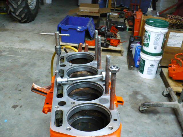
|
|
3 WD45's with power steering,G,D15 fork lift,D19, W-Speed Patrol, "A" Gleaner with a 330 corn head,"66" combine,roto-baler, and lots of Snap Coupler implements to make them work for their keep.
|
|
SteveM C/IL
Orange Level Access
Joined: 12 Sep 2009
Location: Shelbyville IL
Points: 7968
|
Post Options
Thanks(0)
Quote Reply
Posted: 04 Aug 2016 at 11:14pm |
|
ANNUAL. Gotta remove the 2 middle leters
|
|
Allis dave
Orange Level
Joined: 10 May 2012
Location: Northern IN
Points: 2847
|
Post Options
Thanks(0)
Quote Reply
Posted: 05 Aug 2016 at 6:53am |
Thanks Don, always good to hear your comments. Very nice clean looking block Mine started off looking that clean after the hot tank. Then I'd go out and see a little surface rust starting on the gasket surfaces so I oiled them. Then they get wiped off with a break clean rag and cleaned with a scotch Bright on the die grinder. Then I blow everything out again with the air hose before assembly. See Blake? I think you can do a shim job Is there something wrong with the cam that it needs reground? Unless they've sat and rusted, I don't really hear of people having problems with them wearing.
|
|
Allis dave
Orange Level
Joined: 10 May 2012
Location: Northern IN
Points: 2847
|
Post Options
Thanks(0)
Quote Reply
Posted: 05 Aug 2016 at 7:10am |
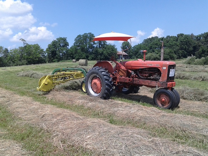
It been a pretty slow rebuild process. It started off with a split to replace seals in the torque tube. You can read about it here if interested http://www.allischalmers.com/forum/forum_posts.asp?TID=120328&title=how-to-or-not-to-split-wd45-replace-sealsThen one Sunday last April I had to drive out to ILL to meet forum member John D and pick this up. It's a little motivation to get this project completed.  Last night I couldn't work either. Was too busy watching this guy. 
|
|
John D
Silver Level


Joined: 12 Sep 2009
Location: Sherman, IL
Points: 360
|
Post Options
Thanks(0)
Quote Reply
Posted: 05 Aug 2016 at 7:39am |
|
Looking good! Keep us posted on your progress
|
|
1964 D17 series 3
|
|
Allis dave
Orange Level
Joined: 10 May 2012
Location: Northern IN
Points: 2847
|
Post Options
Thanks(0)
Quote Reply
Posted: 05 Aug 2016 at 7:58am |
I should also mention that all holes in the block get blown out with the air hose, have a tap ran through them, then blown out again. All parts are from a Reliance/PowerMax kit. I had the engine internally balanced before I started. $350 including surfacing the flywheel. There was 15 gram difference from the lightest to the heaviest piston. Guy said the flywheel and crank were terrible. He said he "pulled his hair out" to finally get it quieted down. I'm hoping for one smooth running motor! Ohh and "Don't mix up the pistons and wrist pins!!" I didn't take any pictures but I wiped out the newly installed cam bearings again and lubed them up with assembly lubed. Lubed up the tappets and dropped them into their places. Lubed up the cam and slid it in making sure to line up the timing marks. Ring GapEven though they came as part of the 8.25 motor kit, I thought I should still check the ring gap. I Installed the spacer and oil rings onto the pistons. I got the ring started down into the sleeve then used the piston to push the ring down until the piston bottomed on the oil ring. I figured this would make sure the ring was square in the (round) hole. lol. All rings gapped at .019 - .022. The book says the gap should be .007-.014. That seemed really tight to me. The people I talked to and what I read said .014 minimum gap for a 4" bore. High performance engine take a wider gap, so I'll pretend this is a high performance Allis and be happy with .019 - .022. I can't change it anyway...  Piston Preparation Piston PreparationI oiled up the rings and pistons good and installed the rings with my ring pliers making sure each ring was 120 degrees from the adjacent ring. According to the instructions, each dot on the ring points to the piston top. I also used the chrome ring as the top ring. Made sure the rings were matched to the sleeve I gapped it in. I followed the service manual instructions to orient the rod and wrist pin correctly in the piston. This is what centers the wrist pin in the piston and keeps this from gouging the cylinder wall. VERY IMPORTANT You can see where he machined off to balance the pistons. Notice the arrow pointing to the front of the block for installation. 
|
|
Don(MO)
Orange Level
Joined: 12 Sep 2009
Location: Bates City MO.
Points: 6862
|
Post Options
Thanks(0)
Quote Reply
Posted: 05 Aug 2016 at 8:15am |
 SteveM C/IL wrote: SteveM C/IL wrote:
ANNUAL. Gotta remove the 2 middle leters |
Yes Steve that's the word. lmao
|
|
3 WD45's with power steering,G,D15 fork lift,D19, W-Speed Patrol, "A" Gleaner with a 330 corn head,"66" combine,roto-baler, and lots of Snap Coupler implements to make them work for their keep.
|
|
79fordblake
Orange Level
Joined: 01 Jul 2010
Location: West Kentucky
Points: 827
|
Post Options
Thanks(0)
Quote Reply
Posted: 05 Aug 2016 at 9:58am |
|
The cam looks in good shape but I was gonna give Bullet Cams a call and see if any improvements can be done to it for a stock build..if not I'll leave it alone. I dropped the head off this morning. Supposed to be around $350. If it needs absolutely everything close to $500. I asked about line boring and he said around $160 so I'm gonna do it and have the whole thing balanced. I'm just having head done right now I'll have to save up a little more money for the rest lol.
|
|
ac45dave
Orange Level Access
Joined: 23 May 2015
Location: SE(IN)
Points: 1317
|
Post Options
Thanks(0)
Quote Reply
Posted: 05 Aug 2016 at 6:19pm |
Dave, not to get off topic, so your the guy that made off with my disc,lol.i saw that the day it went up for sale and almost made a phone call and took off for Ill.wished i had.would have love to had that at the show in rushville today.
|
|
54 wd-45gas ; 56 wd-45d N/F w/fact p/s ; 63 d-17 sIII N/F gas ; 60 D14 N/F ; 67 d-17 sIV N/F gas ; 63D15 sII W/F; 39rc#667 ; 2021 massey 4710 fwa ; gravely 2 wheel tractors
|
|
Allis dave
Orange Level
Joined: 10 May 2012
Location: Northern IN
Points: 2847
|
Post Options
Thanks(0)
Quote Reply
Posted: 05 Aug 2016 at 7:57pm |
Dave,
LOL I guess it was me. John said he had another guy calling about it. You gotta be fast on the phone! I'd been looking for one for a few years now. I don't see as many 9 footers as 7's. Looking forward to being able to drive it on a trailer and take to plow days. I'm a fan of trying to take equipment other than just plows.
I feel a little bad now. But not bad enough to let you have it....
John, You wouldn't believe how many times I've pulled of pieces of that baling wire in the back of the truck for some odd use. I'm about ready to drive back just to get some more!
Don, One thing keeps bugging me, why is there a bolt head sitting on top of one of the studs in your picture of Mike's engine? Did you weld it on to remove the stud? I can see the sleeves. Looks like it turned out good. After looking at mine more. It was only pitted right up to were the top oring sits.I think it will still get a good seal.
Edited by Allis dave - 05 Aug 2016 at 8:03pm
|
|
Don(MO)
Orange Level
Joined: 12 Sep 2009
Location: Bates City MO.
Points: 6862
|
Post Options
Thanks(0)
Quote Reply
Posted: 05 Aug 2016 at 10:50pm |
|
Dave that not a nut, it's a 1/2" fine thread die to clean the threads up with. I changed all the studs out on the engine after trying to clean them up. If the threads or sides of the bolts or studs are not good you might pull them and find your are pulling the head back off to change them. happens on old head bolts/studs a lot.
|
|
3 WD45's with power steering,G,D15 fork lift,D19, W-Speed Patrol, "A" Gleaner with a 330 corn head,"66" combine,roto-baler, and lots of Snap Coupler implements to make them work for their keep.
|
|
Sugarmaker
Orange Level
Joined: 12 Jul 2013
Location: Albion PA
Points: 8167
|
Post Options
Thanks(0)
Quote Reply
Posted: 06 Aug 2016 at 8:30pm |
|
Dave,
Great documentation on the build! So your using a 175 kit in a 45 block right? Should be a good runner. You have plans for this build? Been moving and or pulling AC's all day. That D17 you plowed with this spring, is doing a nice job kicking some butt on the track.
Keep the pictures coming maybe someday I will use your info to build a engine!
Regards,
Chris
|
|
D17 1958 (NFE), WD45 1954 (NFE), WD 1952 (NFE), WD 1950 (WFE), Allis F-40 forklift, Allis CA, Allis D14, Ford Jubilee, Many IH Cub Cadets, 32 Ford Dump, 65 Comet.
|
|
Allis dave
Orange Level
Joined: 10 May 2012
Location: Northern IN
Points: 2847
|
Post Options
Thanks(0)
Quote Reply
Posted: 08 Aug 2016 at 2:44pm |
Rod and Piston InstallationTo start with, I had the rods and caps honed and checked for roundness. A wd45 doesn't have any rod bearing shims so I should be good to go. First thing I noticed was the new rod bearings were narrower than the old Clevite bearings. The old ones measured .530 and the new ones were .430 for a difference of .110.  I used a ring compressor and slid the new pistons in place, making sure to put the correct piston in the correct hole with my marked arrow facing the front of the motor. Once in place, I verified that the wrist pin was slid the correct direction to not gouge the sleeve. I matched the correct rod to cap and made sure the stamped numbers were on the same side and torqued them down to 40ft lbs. A couple of the self locking nuts could be spun on with just my fingers, so I ordered a couple new ones from AGCO to make sure they locked well. I later found out from Don(MO) and Josh Day they I could lay the nuts out on an anvil and get a smaller sized socket to cover the locking "fingers" and give the socket a soft wack to tighten the fingers back up. Then use a dab of red Loctite on the nuts to make sure they stay in place. I'll actually have a chance to do this later, but I don't want to talk about it today... I plastigauged each bearing and came up with .002 - .003 on each one.  You can see the piston is pretty close to the top of the sleeve. The deck clearance measures about .230. These 8.25 pistons should make a lot of power as long as everything holds together. I don't plan on using them to pull the poor tractor to the max. I'll use it on the same size plow to get through the hard spots and maybe an occasional local farm stock pull.  I really like the 65cc piston cup to compress a good air/fuel charge around the spark plug versus the much shallower 32cc bowl used for the Reliance 7.25 D17 piston. The old M&W's I took out had an even larger 73cc bowl.
|
|
79fordblake
Orange Level
Joined: 01 Jul 2010
Location: West Kentucky
Points: 827
|
Post Options
Thanks(0)
Quote Reply
Posted: 08 Aug 2016 at 5:15pm |
|
What head gasket are you using? I may try finding one that is a little thinner than the one in my gasket kit. You going to use a D17 governor spring? I ordered new connecting rod nuts as well. I cleaned and painted timing cover over the weekend and replaced the throttle shaft bushings.
Edited by 79fordblake - 08 Aug 2016 at 5:18pm
|
|
Allis dave
Orange Level
Joined: 10 May 2012
Location: Northern IN
Points: 2847
|
Post Options
Thanks(0)
Quote Reply
Posted: 09 Aug 2016 at 8:15am |
|
Blake, sounds like you're making good progress. Making sure you have everything checked out and cleaned up first makes the assembly a lot easier. I'm learning that... I'm using the head gasket that came with the reliance kit. If I was you, I'd get a Victor Reinz gasket set. It has a better head gasket (copper rings around all the water and oil gallys). They also have the correct front main seal.
|
|
Allis dave
Orange Level
Joined: 10 May 2012
Location: Northern IN
Points: 2847
|
Post Options
Thanks(0)
Quote Reply
Posted: 09 Aug 2016 at 9:53am |
Timing coverI cleaned up the timing cover good and checked the throttle bushings and governor fingers. The bushings are tight. The fingers show a little wear, but I don’t think bad enough to need welded and ground back down. Be careful when handling the cover. If you bend the linkage arm it will throw your carborator out of adjustment and cause surging or other issues. I used a scotch bright disk on the end of my die grinder to clean the gasket surfaces. I tested on a pop can to make sure the pad wouldn’t take off metal. I bought the wrong pads once that contained grit and would take off metal. I tried to make up an alignment tool out of PVC like Don suggested but wasn’t finding the right stuff. I found this bearing collar for about $7. It was the right size but needed touched up a little on the lathe. Gay at work took it home and fixed it up for me. He charged me a cherry pie pastry for the work. I actually bought him 4. Total $9  I slid the alignment tool into the cover and painted on a thin layer #3 permatex onto both sides of the gasket and bolted the cover into place. I probably didn’t need sealer, but I feel better knowing any little pits are filled. I hate leaks. I like to #3 for this purpose because a thin layer can be painted on without a lot of oozing. The gasket kit with the Reliance kit only had 2 front main seal. One that was way to big, and one that seemed the right size and had an extra felt protective layer on the outside. The service manual says newer (1950’s newer I suppose) seals have the felt to protect the seal. Apparently this is NOT that seal. It could all I had to get it on the crank and pretty much ruined the seal. A call to my reliance dealer and he says that’s a slightly smaller seal for a WD crank. He sent me 2 of the correct seals. I quick look at my old leftover Victor Reinz and I still have the too big seal (probably for a D17) and the too small felt covered seal. Looks like that kit cam with all 3 seals and I already used the correct one previously. WD Seal, It's a little beat up, this is after I starting trying to get it back off  I chamfered the end of the crank a little to help get the seal started. I oiled up the seal and shaft good. Apparently I didn’t chamfer enough because I rolled over a small part of the seal. Really chamfered the heck out it next time and the seal went on well. HEY, that alignment tool works great to tap the seal in place too. 
|
|
79fordblake
Orange Level
Joined: 01 Jul 2010
Location: West Kentucky
Points: 827
|
Post Options
Thanks(0)
Quote Reply
Posted: 09 Aug 2016 at 12:19pm |
|
The victor set is what I got and some of it seems poor quality. The (F) gaskets for under the main cap are wrong. Sandy Lake Implement is currently trying to find out for me if the Agco oil pan kit comes woth the correct ones. I made a tool from a pipe I had laying around to center timing cover when I get to that point.
Edited by 79fordblake - 09 Aug 2016 at 12:20pm
|
|
Allis dave
Orange Level
Joined: 10 May 2012
Location: Northern IN
Points: 2847
|
Post Options
Thanks(0)
Quote Reply
Posted: 09 Aug 2016 at 12:54pm |
|
I know for sure that a felpro main kit comes with both sizes of F gaskets. I'm not sure about the Felpro oil pan gasket kit. I ordered one today from NAPA and will have it to tomorrow. $16. I'll let you know what's in it.
|
|
DrAllis
Orange Level Access
Joined: 12 Sep 2009
Points: 19473
|
Post Options
Thanks(0)
Quote Reply
Posted: 09 Aug 2016 at 1:08pm |
|
I always take a piece of good quality black electrical tape and thinly wrap it around the crankshaft snout like a barber pole. Keep overlap to a minimum and start away from the crank end and spriol to the end. Spray some WD-40 on the tape and slide the oil seal onto the shaft and have no fear of cutting the seal when going over the setscrew holes or half-moon keyway. Remove tape when seal is installed.
|
|
79fordblake
Orange Level
Joined: 01 Jul 2010
Location: West Kentucky
Points: 827
|
Post Options
Thanks(0)
Quote Reply
Posted: 09 Aug 2016 at 2:24pm |
|
Dave what was the number for the felpro rear main kit? I already have a entire kit so if i don't have to spend the money on a Agco oil pan kit to get the F gaskets that would be great.
|
|
Allis dave
Orange Level
Joined: 10 May 2012
Location: Northern IN
Points: 2847
|
Post Options
Thanks(0)
Quote Reply
Posted: 09 Aug 2016 at 2:39pm |
Here's the link to NAPA's site. part# FPG BS40010 https://www.napaonline.com/napa/en/p/FPBBS40010/FPBBS40010_0232675384Thanks for the tip Doc. That's a good idea.
Edited by Allis dave - 09 Aug 2016 at 2:41pm
|
|
Sugarmaker
Orange Level
Joined: 12 Jul 2013
Location: Albion PA
Points: 8167
|
Post Options
Thanks(0)
Quote Reply
Posted: 09 Aug 2016 at 9:34pm |
|
Dave,
Your coming right along and helping others during your journey!
Regards,
Chris
|
|
D17 1958 (NFE), WD45 1954 (NFE), WD 1952 (NFE), WD 1950 (WFE), Allis F-40 forklift, Allis CA, Allis D14, Ford Jubilee, Many IH Cub Cadets, 32 Ford Dump, 65 Comet.
|
|
Allis dave
Orange Level
Joined: 10 May 2012
Location: Northern IN
Points: 2847
|
Post Options
Thanks(0)
Quote Reply
Posted: 10 Aug 2016 at 11:35am |
Oil PumpFor my Full Flow oil system conversion I purchased a used oil pump from Bill Deppe with internal regulator and it already had the 10 tooth gear. Great working with Bill by the way. Would definitely buy parts from him again. There was a little bit of junk between the screen and cover so I took the cover off and sprayed the pump and cover out really good with the water hose. After I installed the pump I kept having a nagging feeling that I should've pulled the cover and checked it out. I'm glad I did because I found a relief valve spring with about 1/2" broken off the end. Purchased a new one from AGCO for $7 and it came drop shipped from MinnPar in a MinnPar box. Guess where some AGCO "OEM" parts are sourced from??? The new spring was a little thinner, but also longer. Hopefully the difference is a wash and I get 30PSI from it. Once it's together there's no changing it without dropping the pan, unlike a standard WD45 with the pressure valve in the side of the bock. Once I was in there I decided to pull the drive shaft out and check it for wear. To pull the shaft I had to drive the roll pin out of the gear. The gear is also lightly pressed onto the shaft so I drove the shaft off the gear with a brass punch. I got lucky during re-assembly and managed to get the roll pin holes perfectly lined up after tapping the gear back onto the shaft with a block of wood and hammer. The picture makes it look like more wear than what's really there. The shaft was perfectly smooth with no wear spots. I had more than one person tell me that these old oil pumps never die. I guess they were right. They never said anything about relief valves...    With the method I chose, I had to make a new oil line to go form the pump to block. I tried not to pinch the line while bending. I think I did ok. I'll make a new post about the full flow conversion one of these days. 
|
|
Brian Jasper co. Ia
Orange Level
Joined: 11 Sep 2009
Location: Prairie City Ia
Points: 10508
|
Post Options
Thanks(0)
Quote Reply
Posted: 10 Aug 2016 at 11:59am |
Don(MO) wrote:
Dave that not a nut, it's a 1/2" fine thread die to clean the threads up with. I changed all the studs out on the engine after trying to clean them up. If the threads or sides of the bolts or studs are not good you might pull them and find your are pulling the head back off to change them. happens on old head bolts/studs a lot.
|
Happens on Cadillac North Star too. Aluminum block with no thread inserts. :(
|
|
"Any man who thinks he can be happy and prosperous by letting the government take care of him better take a closer look at the American Indian." Henry Ford
|
|
Brian Jasper co. Ia
Orange Level
Joined: 11 Sep 2009
Location: Prairie City Ia
Points: 10508
|
Post Options
Thanks(0)
Quote Reply
Posted: 10 Aug 2016 at 12:06pm |
|
Looks good Dave. Do all of the connecting rod clamp bolts face the same side and you just position the rods on the pins in order to have everything line up correctly?
|
|
"Any man who thinks he can be happy and prosperous by letting the government take care of him better take a closer look at the American Indian." Henry Ford
|
|
79fordblake
Orange Level
Joined: 01 Jul 2010
Location: West Kentucky
Points: 827
|
Post Options
Thanks(0)
Quote Reply
Posted: 10 Aug 2016 at 5:26pm |
|
Did you get new rod bolts or just nuts? My bolts don't appear to have any damage the nuts are fine to other than they look like a socket may have slipped on them some so I just went ahead and got new. Did you get your gasket kit yet?
|
|


